EP2632025A1 - Système de fixation d'éléments magnétiques dans une machine électrique à aimants permanents. - Google Patents
Système de fixation d'éléments magnétiques dans une machine électrique à aimants permanents. Download PDFInfo
- Publication number
- EP2632025A1 EP2632025A1 EP13155701.9A EP13155701A EP2632025A1 EP 2632025 A1 EP2632025 A1 EP 2632025A1 EP 13155701 A EP13155701 A EP 13155701A EP 2632025 A1 EP2632025 A1 EP 2632025A1
- Authority
- EP
- European Patent Office
- Prior art keywords
- rotor
- magnetic element
- fixing device
- magnetic
- fastening
- Prior art date
- Legal status (The legal status is an assumption and is not a legal conclusion. Google has not performed a legal analysis and makes no representation as to the accuracy of the status listed.)
- Withdrawn
Links
- 239000000463 material Substances 0.000 claims abstract description 9
- 239000002131 composite material Substances 0.000 claims abstract description 6
- 239000002184 metal Substances 0.000 claims abstract description 4
- 239000007769 metal material Substances 0.000 claims abstract description 3
- 239000002775 capsule Substances 0.000 claims description 15
- 230000001681 protective effect Effects 0.000 claims description 13
- 230000000295 complement effect Effects 0.000 claims description 4
- 229910001220 stainless steel Inorganic materials 0.000 abstract description 2
- 239000010935 stainless steel Substances 0.000 abstract description 2
- 239000003365 glass fiber Substances 0.000 abstract 1
- 230000004907 flux Effects 0.000 description 6
- 230000007797 corrosion Effects 0.000 description 3
- 238000005260 corrosion Methods 0.000 description 3
- 230000037431 insertion Effects 0.000 description 3
- 238000003780 insertion Methods 0.000 description 3
- 238000004519 manufacturing process Methods 0.000 description 3
- 210000000080 chela (arthropods) Anatomy 0.000 description 2
- 238000003754 machining Methods 0.000 description 2
- 239000000696 magnetic material Substances 0.000 description 2
- 229920005989 resin Polymers 0.000 description 2
- 239000011347 resin Substances 0.000 description 2
- 238000004026 adhesive bonding Methods 0.000 description 1
- 238000012550 audit Methods 0.000 description 1
- 230000005540 biological transmission Effects 0.000 description 1
- 238000006243 chemical reaction Methods 0.000 description 1
- 238000005516 engineering process Methods 0.000 description 1
- 239000003822 epoxy resin Substances 0.000 description 1
- 239000011152 fibreglass Substances 0.000 description 1
- 239000000945 filler Substances 0.000 description 1
- LNEPOXFFQSENCJ-UHFFFAOYSA-N haloperidol Chemical compound C1CC(O)(C=2C=CC(Cl)=CC=2)CCN1CCCC(=O)C1=CC=C(F)C=C1 LNEPOXFFQSENCJ-UHFFFAOYSA-N 0.000 description 1
- 229920000647 polyepoxide Polymers 0.000 description 1
- 239000013535 sea water Substances 0.000 description 1
- 238000007789 sealing Methods 0.000 description 1
Images


Classifications
-
- H—ELECTRICITY
- H02—GENERATION; CONVERSION OR DISTRIBUTION OF ELECTRIC POWER
- H02K—DYNAMO-ELECTRIC MACHINES
- H02K1/00—Details of the magnetic circuit
- H02K1/06—Details of the magnetic circuit characterised by the shape, form or construction
- H02K1/22—Rotating parts of the magnetic circuit
- H02K1/27—Rotor cores with permanent magnets
- H02K1/2793—Rotors axially facing stators
- H02K1/2795—Rotors axially facing stators the rotor consisting of two or more circumferentially positioned magnets
- H02K1/2796—Rotors axially facing stators the rotor consisting of two or more circumferentially positioned magnets where both axial sides of the rotor face a stator
-
- H—ELECTRICITY
- H02—GENERATION; CONVERSION OR DISTRIBUTION OF ELECTRIC POWER
- H02K—DYNAMO-ELECTRIC MACHINES
- H02K1/00—Details of the magnetic circuit
- H02K1/06—Details of the magnetic circuit characterised by the shape, form or construction
- H02K1/22—Rotating parts of the magnetic circuit
- H02K1/27—Rotor cores with permanent magnets
- H02K1/2706—Inner rotors
- H02K1/272—Inner rotors the magnetisation axis of the magnets being perpendicular to the rotor axis
- H02K1/274—Inner rotors the magnetisation axis of the magnets being perpendicular to the rotor axis the rotor consisting of two or more circumferentially positioned magnets
- H02K1/2753—Inner rotors the magnetisation axis of the magnets being perpendicular to the rotor axis the rotor consisting of two or more circumferentially positioned magnets the rotor consisting of magnets or groups of magnets arranged with alternating polarity
- H02K1/278—Surface mounted magnets; Inset magnets
-
- H—ELECTRICITY
- H02—GENERATION; CONVERSION OR DISTRIBUTION OF ELECTRIC POWER
- H02K—DYNAMO-ELECTRIC MACHINES
- H02K2213/00—Specific aspects, not otherwise provided for and not covered by codes H02K2201/00 - H02K2211/00
- H02K2213/12—Machines characterised by the modularity of some components
-
- H—ELECTRICITY
- H02—GENERATION; CONVERSION OR DISTRIBUTION OF ELECTRIC POWER
- H02K—DYNAMO-ELECTRIC MACHINES
- H02K7/00—Arrangements for handling mechanical energy structurally associated with dynamo-electric machines, e.g. structural association with mechanical driving motors or auxiliary dynamo-electric machines
- H02K7/18—Structural association of electric generators with mechanical driving motors, e.g. with turbines
- H02K7/1807—Rotary generators
- H02K7/1823—Rotary generators structurally associated with turbines or similar engines
- H02K7/183—Rotary generators structurally associated with turbines or similar engines wherein the turbine is a wind turbine
-
- H—ELECTRICITY
- H02—GENERATION; CONVERSION OR DISTRIBUTION OF ELECTRIC POWER
- H02K—DYNAMO-ELECTRIC MACHINES
- H02K7/00—Arrangements for handling mechanical energy structurally associated with dynamo-electric machines, e.g. structural association with mechanical driving motors or auxiliary dynamo-electric machines
- H02K7/18—Structural association of electric generators with mechanical driving motors, e.g. with turbines
- H02K7/1807—Rotary generators
- H02K7/1823—Rotary generators structurally associated with turbines or similar engines
- H02K7/183—Rotary generators structurally associated with turbines or similar engines wherein the turbine is a wind turbine
- H02K7/1838—Generators mounted in a nacelle or similar structure of a horizontal axis wind turbine
Definitions
- the present invention relates to a system for fixing magnetic elements in an electrical machine with permanent magnets comprising at least one stator and at least one rotor packed with a plurality of magnetic elements, a magnetic element comprising at least one permanent magnet.
- the invention is more generally in the field of energy conversion by rotating electrical machines with permanent magnets. It finds a particular application especially in the tidal and wind fields.
- Such an electrical machine with permanent magnets is for example a generator or a motor.
- An axial flux permanent magnet machine has one or more circular stators.
- the disk-shaped rotor is positioned between the stators and comprises a large number of magnetic elements comprising magnets of high power, possibly encapsulated in a capsule of protection, positioned radially on the rotor.
- a radial flux permanent magnet machine conventionally comprises a cylindrical stator mounted concentrically outside or inside a cylindrical rotor. Permanent magnets, possibly placed in a protective cap, are positioned on the rotor at locations provided for this purpose.
- the magnetic elements can be subjected to fatigue forces induced by rotation and torque transmission, wear and corrosion (if submerged application ) during operation of the electric machine. It is important to secure each magnetic element as securely as possible, to ensure proper operation and to avoid significant wear or loosening of the elements, due to fatigue forces and vibrations during rotation of the rotor.
- a known conventional system is to fix each magnetic element to the electric machine, for example on the rotor, by gluing, using epoxy resins.
- a fastening system has a significant risk of takeoff, in particular due to the impact of seawater on the resistance of the resin in submerged operation.
- Another conventional known fastening system is to assemble one or more fasteners, for example screws, directly on the magnetic element, to fix it on the rotor or the stator.
- the magnetic element is simply a magnet without protective cap, such a solution involves machining directly on the magnetic material, and the risk of damaging this material is high.
- the magnetic element recovers the fixing forces and the result is that it is weakened and may be damaged or loosened in time , the magnetic material being very fragile.
- the magnetic element is composed of one or more magnets encapsulated in a protective cap, such a capsule must be manufactured according to very precise manufacturing constraints in order to ensure good fixation without significant play.
- the invention proposes a system for fixing magnetic elements in an electrical machine with permanent magnets comprising at least one stator and at least one rotor packed with a plurality of magnetic elements, a magnetic element comprising at least one permanent magnet.
- the fastening system comprises, for fixing a magnetic element to the rotor, a fixing device able to be positioned in contact with a portion of the magnetic element and to be fixed to the rotor by means of at least one mechanical element. fixing means, so as to fix said magnetic element to the rotor when said mechanical fastening element is in engagement with the rotor.
- the fixing device supports the fixing forces, the permanent magnet magnetic element being protected because it is not directly connected to the rotor. Only the fixing device needs to have a precise mechanical interface with the rotor, ie contact surfaces with precise tolerances. The constraints and manufacturing costs of the magnetic elements are thus reduced.
- FIG. figure 1 A rotor 10 of an axial flow electric machine is shown schematically in FIG. figure 1 .
- an axial flow electric machine is composed of at least one disk-shaped rotor rotatable about an axis of rotation, and in this embodiment, two concentric circular stators. to the rotor which are not shown in the figure.
- the rotor 10 is lined with a set of magnetic elements 12, each comprising one or more magnets permanent, arranged at regular intervals, in the radial plane of the rotor, along radii of the rotor 10.
- the rotor shown in Figure 10 is lined with magnetic elements 12, previously mounted, for example by insertion into the radial plane, at regular intervals, at locations provided for this purpose.
- each magnetic element 12 comprises a permanent magnet encapsulated in a box or protective cap, and fixed inside the protective cap with a filler material, for example a resin.
- a magnetic element 12 is simply formed of a permanent magnet.
- the magnetic elements 12 are fixed to the rotor 10 not by direct attachment, but via a fastening device 14, as shown in more detail in FIGS. figures 2 and 3 .
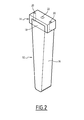
- the figure 2 illustrates for perspective a fastening device 14 integral with a magnetic element 12.
- the magnetic element 12 of this embodiment comprises a trapezoidal protective cap 16 adapted to receive one or more permanent magnets, a closure element 18 capable of sealing the permanent magnet or magnets inside the capsule 16, so as to to protect the magnets from corrosion.
- the capsule 16 is preferably made of stainless material, so as to protect the permanent magnet (s) from corrosion.
- Several materials may be usable such as stainless steel, fiberglass or other composites.
- the fixing device 14 is positioned in contact with the closing element 18, so as to cover its face situated opposite the face in contact with the capsule 16. Thus, the fixing device 14 is positioned so as to to fix the magnetic element 12 to the rotor 10.
- the fixing device 14 comprises pre-arranged holes 20, each hole allowing the insertion of a mechanical fastening element, for example a screw or a pin, able to firmly fix the rotor attachment device 10.
- the fixing device 14 also comprises a hole 22 adapted to receive another mechanical fastening element intended to secure the fastening device 14 to the magnetic element 12.
- screws 24 passing through the holes 20 for engaging portions of the rotor 10 secure the fixing device 14 to the rotor 10, and because of the positioning of the device fastening 14 relative to the magnetic element 12, the attachment of the magnetic element 12 to the rotor 10.
- the mechanical fastening elements 24 are assembled in the radial direction of the capsule 16, which is the direction of insertion of the magnets , so that the fixing device 14 positions the magnetic element 12 in pincers with respect to the rotor.
- the magnetic element 12 is positioned between the fixing device 14 and the rotor 10, which ensures the attachment of this magnetic element 12 via the fastening of the fixing device 14 to the rotor.
- a screw 26 is also used to secure the fastening device 14 to the magnetic element 12.
- the screw 26 is preferably in engagement with the closing element 18 of the capsule 16 of the magnetic element 12, thus avoiding contact with the permanent magnet 28. Thus, no machining is performed directly on the permanent magnet.
- a complementary mechanical fixing element 30 is added, making it possible to better secure the capsule 16 to the rotor 10.
- a pin 30 centered with respect to the capsule 16 is added on the opposite face of the magnetic element 12 with respect to the face in contact with the fixing device 14. This pin 30 is able to fit into a machined hole in the rotor 10.
- the complementary mechanical fixing element 30 is integrated in the capsule 16.
- the fixing device 14 is, in the preferred embodiment, a machined mechanical part having a good mechanical interface with the rotor.
- the material used for the manufacture of such a fixing device 14 is a non-magnetic metal or a composite material.
- a fixing device similar to the device 14 is provided for several magnetic elements 12. According to the principle described above, the fixing device is then placed on the outer portions of the magnetic elements 12, so as to to fix them to the rotor when it is itself secured to the rotor via mechanical fasteners.
- a fixing system using a fixing device is implemented in a radial flow electric machine.
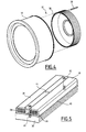
- the figure 4 illustrates, in an exploded view, a radial flow electric machine 32 composed of a stator 34 in the shape of a circular ring, inside which is placed a rotor 36, which is filled with magnetic elements 38 with permanent magnets over the entire cylindrical ring, positioned at regular intervals in the axial direction of the rotor.
- each magnetic element 38 is composed of a capsule or box 40, able to encapsulate one or more permanent magnets 28.
- the magnetic elements 38 are placed on the rotor 36, and secured thereto by means of fixing devices 42.
- a fixing device 42 is able to fix two magnetic elements 38.
- the fixing element 42 has a shape suitable for being placed in contact on a portion of the outer face of each protective cap 40 of a magnetic element 38.
- the attachment device 42 has a trapezoidal cross-sectional shape so as to conform to the shape of the adjacent protective caps 40.
- the contact between a face of the fixing device 42 and a magnetic element 38 is provided in this embodiment over the entire surface of the face of the magnetic element 38 concerned.
- the contact is provided on a portion of this face only, it being understood that the contact surface is sufficient to ensure that the fixing slide 42 is securely fastened to the magnetic element 38, so as to ensure a fixation of the magnetic element 38 to the rotor 36.
- the fixing device 42 comprises pre-arranged holes 44 each adapted to receive a fixing element 46, for example a screw or a pin.
- a fixing element 46 for example a screw or a pin.
- Each fastening element 46 is fixed in engagement with the rotor 36 so as to fasten the fastening device 42 to the rotor, and consequently the attachment to the rotor 36 of the magnetic elements 38 in contact with the fixing device 42.
- the fixing device 42 is positioned in contact with portions of magnetic elements 38, so as to ensure a pincer attachment of said magnetic elements 38 to the rotor, but without the use of direct fasteners between the elements. magnetic devices 38 and the fixing device 42.
- fastening devices In addition to securely fastening each magnetic element to the rotor, the use of fastening devices according to the invention provides good rigidity to the rotor lined with permanent magnets, greater than the rigidity obtained by direct attachment without additional fastening device, and therefore ensures better operation and wear resistance of the electric machine as a whole.
Landscapes
- Engineering & Computer Science (AREA)
- Power Engineering (AREA)
- Permanent Field Magnets Of Synchronous Machinery (AREA)
Abstract
Description
- La présente invention concerne un système de fixation d'éléments magnétiques dans une machine électrique à aimants permanents comportant au moins un stator et au moins un rotor garni d'une pluralité d'éléments magnétiques, un élément magnétique comportant au moins un aimant permanent.
- L'invention se situe plus généralement dans le domaine de la conversion d'énergie par des machines électriques tournantes à aimants permanents. Elle trouve une application particulière notamment dans les domaines hydrolien et éolien.
- Une telle machine électrique à aimants permanents est par exemple un générateur ou un moteur.
- Dans ce type d'application, des machines électriques de très grande taille sont souvent nécessaires.
- Deux types de machines électriques à aimants permanents sont connus, les machines à flux axial et les machines à flux radial. D'autres technologies existent mais peu répandues à l'échelle industrielle comme la topologie de machine à flux transverse.
- Une machine à aimants permanents à flux axial comporte un ou plusieurs stators circulaires. Dans le cas d'une configuration à deux stators et un rotor médian, le rotor, en forme de disque, est positionné entre les stators et comprend un grand nombre d'éléments magnétiques comportant des aimants de forte puissance, éventuellement encapsulés dans une capsule de protection, positionnés de façon radiale sur le rotor.
- Une machine à aimants permanents à flux radial comporte classiquement un stator cylindrique monté de façon concentrique à l'extérieur ou à l'intérieur d'un rotor cylindrique. Des aimants permanents, éventuellement placés dans une capsule de protection, sont positionnés sur le rotor à des emplacements prévus à cet effet.
- Qu'il s'agisse d'une machine à flux axial ou à flux radial, les éléments magnétiques peuvent être soumis aux efforts de fatigue induits par la rotation et la transmission de couple, à l'usure et à la corrosion (si application immergée) lors du fonctionnement de la machine électrique. Il est important de bien fixer chaque élément magnétique aussi solidement que possible, afin d'assurer un bon fonctionnement et d'éviter une usure importante ou un desserrage des éléments, dû aux efforts de fatigue et aux vibrations lors de la rotation du rotor.
- Un système classique connu consiste à fixer chaque élément magnétique à la machine électrique, par exemple sur le rotor, par collage, en utilisant des résines époxy. Cependant, un tel système de fixation présente un risque de décollage important, notamment dû à l'impact de l'eau de mer sur la résistance de la résine en fonctionnement immergé.
- Un autre système de fixation classique connu consiste à assembler un ou plusieurs éléments de fixation, par exemple des vis, directement sur l'élément magnétique, afin de fixer celui-ci sur le rotor ou le stator. Dans le cas où l'élément magnétique est simplement un aimant sans capsule de protection, une telle solution implique un usinage directement sur la matière magnétique, et le risque d'endommager cette matière est élevé. De plus, dans le cas d'une fixation directe de chaque élément magnétique via un élément mécanique de fixation, l'élément magnétique récupère les efforts de fixation et le résultat est qu'il est fragilisé et risque d'être endommagé ou desserré à terme, la matière magnétique étant très fragile. Dans le cas où l'élément magnétique est composé d'un ou plusieurs aimants encapsulés dans une capsule de protection, une telle capsule doit être fabriquée selon des contraintes de fabrication très précises afin d'assurer une bonne fixation sans jeu important.
- Afin de remédier aux inconvénients précités, l'invention propose un système de fixation d'éléments magnétiques dans une machine électrique à aimants permanents comportant au moins un stator et au moins un rotor garni d'une pluralité d'éléments magnétiques, un élément magnétique comportant au moins un aimant permanent.
- Le système de fixation comporte, pour la fixation d'un élément magnétique au rotor, un dispositif de fixation apte à être positionné en contact avec une portion de l'élément magnétique et à être fixé au rotor au moyen d'au moins un élément mécanique de fixation, de manière à fixer ledit élément magnétique au rotor lorsque ledit élément mécanique de fixation est en prise avec le rotor.
- Avantageusement, le dispositif de fixation supporte les efforts de fixation, l'élément magnétique à aimants permanents étant protégé, car il n'est pas lié directement au rotor. Seul le dispositif de fixation a besoin d'avoir une interface mécanique précise avec le rotor, c'est à dire des surfaces de contact avec des tolérances précises. Les contraintes et les coûts de fabrication des éléments magnétiques sont ainsi diminués.
- Le système de fixation d'éléments magnétiques dans une machine électrique à aimants permanents selon l'invention peut également présenter une ou plusieurs des caractéristiques ci-dessous, prises indépendamment ou en combinaison :
- ledit dispositif de fixation comporte au moins un trou apte à recevoir un dit élément mécanique de fixation,
- ledit élément mécanique de fixation est une vis ou une goupille, apte à être insérée dans ledit dispositif de fixation en prise avec le rotor,
- ledit élément magnétique comporte une capsule de protection à l'intérieur de laquelle est disposé au moins un aimant permanent,
- ladite capsule de protection comporte en outre un matériau de remplissage apte à fixer le ou les aimants permanents,
- lorsque ladite machine électrique est une machine à flux axial, ledit élément magnétique comporte en outre un élément de fermeture apte à sceller ladite capsule de protection,
- ledit dispositif de fixation est positionné en contact avec une surface dudit élément de fermeture, et ledit dispositif de fixation est en outre fixé audit élément de fermeture par au moins un autre élément mécanique de fixation,
- ledit dispositif de fixation est formé de manière à ce qu'une de ses faces soit apte à être positionnée au contact d'au moins une portion d'une face de l'élément magnétique,
- il comporte en outre un élément mécanique complémentaire de fixation, fixé sur une autre face de l'élément magnétique et apte à être positionné en prise avec le rotor,
- ledit dispositif de fixation est une pièce métallique usinée, et
- ledit dispositif de fixation est en métal non magnétique ou en matériau composite.
- D'autres caractéristiques et avantages de l'invention ressortiront de la description qui en est donnée ci-dessous, à titre indicatif et nullement limitatif, en référence aux figures annexées, parmi lesquelles :
- la
figure 1 est une vue de dessus d'un rotor d'une machine électrique à flux axial selon un mode de réalisation ; - la
figure 2 est une vue en perspective d'un dispositif de fixation positionné sur un élément magnétique selon un mode de réalisation ; - la
figure 3 est une vue en coupe longitudinale du dispositif de fixation positionné sur un élément magnétique de lafigure 2 ; - la
figure 4 est une vue éclatée d'une machine électrique à flux radial, et - la
figure 5 est une vue en perspective d'un dispositif de fixation d'éléments magnétiques selon un autre mode de réalisation de l'invention. - Un rotor 10 d'une machine électrique à flux axial est représenté schématiquement à la
figure 1 . Comme il a été rappelé ci-dessus, une machine électrique à flux axial est composée d'au moins un rotor en forme de disque apte à tourner autour d'un axe de rotation, et dans ce mode de réalisation, de deux stators circulaires concentriques au rotor qui ne sont pas représentés sur la figure. - Pour le fonctionnement de la machine électrique à flux axial, le rotor 10 est garni d'un ensemble d'éléments magnétiques 12, comportant chacun un ou plusieurs aimants permanents, disposés à intervalles réguliers, dans le plan radial du rotor, selon des rayons du rotor 10.
- Le rotor représenté à la figure 10 est garni d'éléments magnétiques 12, préalablement montés, par exemple par insertion dans le plan radial, à intervalles réguliers, à des emplacements prévus à cet effet.
- Dans un mode de réalisation, chaque élément magnétique 12 comporte un aimant permanent encapsulé dans un caisson ou capsule de protection, et fixé à l'intérieur de la capsule de protection à l'aide d'un matériau de remplissage, par exemple une résine.
- Dans une variante, un élément magnétique 12 est simplement formé d'un aimant permanent.
- Les éléments magnétiques 12 sont fixés au rotor 10 non pas par fixation directe, mais via un dispositif de fixation 14, tel que représenté plus en détail dans les
figures 2 et3 . - La
figure 2 illustre en vue de perspective un dispositif de fixation 14 solidaire à un élément magnétique 12. - L'élément magnétique 12 de ce mode de réalisation comporte une capsule de protection trapézoïdale 16 apte à recevoir un ou plusieurs aimants permanents, un élément de fermeture 18 apte à sceller le ou les aimants permanents à l'intérieur de la capsule 16, de manière à protéger les aimants de toute corrosion.
- La capsule 16 est de préférence en matériau inoxydable, de manière à protéger le ou les aimants permanents de la corrosion. Plusieurs matières pourraient être utilisables comme l'acier inoxydable, la fibre de verre ou d'autres composites.
- Le dispositif de fixation 14 est positionné au contact de l'élément de fermeture 18, de manière à recouvrir sa face située à l'opposé de la face en contact avec la capsule 16. Ainsi, le dispositif de fixation 14 est positionné de manière à fixer l'élément magnétique 12 au rotor 10. Le dispositif de fixation 14 comporte des trous 20 pré-aménagés, chaque trou permettant l'insertion d'un élément mécanique de fixation, par exemple une vis ou une goupille, apte à fixer solidement le dispositif de fixation au rotor 10.
- De manière optionnelle le dispositif de fixation 14 comporte également un trou 22 apte à recevoir un autre élément mécanique de fixation ayant pour objet de solidariser le dispositif de fixation 14 à l'élément magnétique 12.
- En variante, plusieurs trous 22 sont prévus pour la solidarisation du dispositif de fixation 14 à l'élément magnétique 12.
- Ainsi, comme illustré dans la vue de coupe longitudinale de la
figure 3 , des vis 24 traversant les trous 20 pour venir en prise avec des portions du rotor 10 assurent la fixation du dispositif de fixation 14 au rotor 10, et, du fait du positionnement du dispositif de fixation 14 par rapport à l'élément magnétique 12, la fixation de l'élément magnétique 12 au rotor 10. Les éléments mécaniques de fixation 24 sont assemblés selon la direction radiale de la capsule 16, qui est la direction d'insertion des aimants, de manière à ce que le dispositif de fixation 14 positionne l'élément magnétique 12 en tenaille par rapport au rotor. En effet, au moins sur une portion du dispositif de fixation 14, l'élément magnétique 12 est positionné entre le dispositif de fixation 14 et le rotor 10, ce qui assure la fixation de cet élément magnétique 12 via la fixation du dispositif de fixation 14 au rotor. - Optionnellement, une vis 26 est également utilisée pour solidariser le dispositif de fixation 14 à l'élément magnétique 12. Comme on le voit sur la
figure 3 , de préférence la vis 26 est en prise simplement avec l'élément de fermeture 18 de la capsule 16 de l'élément magnétique 12, évitant ainsi le contact avec l'aimant permanent 28. Ainsi, aucun usinage n'est effectué directement sur l'aimant permanent. - Optionnellement, un élément mécanique complémentaire de fixation 30 est ajouté, permettant de mieux solidariser la capsule 16 au rotor 10. Dans le mode de réalisation illustré à la
figure 3 , une goupille 30 centrée par rapport à la capsule 16 est ajoutée sur la face opposée de l'élément magnétique 12 par rapport à la face en contact avec le dispositif de fixation 14. Cette goupille 30 est apte à s'insérer dans un trou usiné dans le rotor 10. Dans un mode de réalisation, l'élément mécanique complémentaire de fixation 30 est intégré dans la capsule 16. - Le dispositif de fixation 14 est, dans le mode de réalisation préféré, une pièce mécanique usinée, présentant une bonne interface mécanique avec le rotor.
- De préférence, le matériau utilisé pour la fabrication d'un tel dispositif de fixation 14 est un métal non magnétique ou un matériau composite.
- Dans un mode de réalisation alternatif, un dispositif de fixation similaire au dispositif 14 est prévu pour plusieurs éléments magnétiques 12. Selon le principe décrit ci-dessus, le dispositif de fixation est alors placé sur les portions externes des éléments magnétiques 12, de manière à les fixer au rotor lorsqu'il est lui-même solidarisé au rotor via des éléments de fixation mécanique.
- Selon un deuxième mode de réalisation décrit en référence aux
figures 4 et 5 , un système de fixation utilisant un dispositif de fixation est mis en oeuvre dans une machine électrique à flux radial. - La
figure 4 illustre, dans une vue éclatée, une machine électrique à flux radial 32, composée d'un stator 34 en forme de couronne circulaire, à l'intérieur duquel est placé un rotor 36, qu'on garnit d'éléments magnétiques 38 à aimants permanents sur toute la couronne cylindrique, positionnés à intervalles réguliers selon la direction axiale du rotor. - Comme illustré à la
figure 5 , dans un mode de réalisation chaque élément magnétique 38 est composé d'une capsule ou caisson 40, apte à encapsuler un ou plusieurs aimants permanents 28. - Les éléments magnétiques 38 sont posés sur le rotor 36, et solidarisés à celui-ci grâce à des dispositifs de fixation 42.
- Dans le mode de réalisation illustré à la
figure 5 , un dispositif de fixation 42 est apte à fixer deux éléments magnétiques 38. L'élément de fixation 42 a une forme appropriée pour être positionné en contact sur une portion de la face extérieure de chaque capsule de protection 40 d'un élément magnétique 38. Dans le mode de réalisation illustré, le dispositif de fixation 42 a une forme trapézoïdale en coupe transversale, de manière à épouser la forme des capsules de protection 40 adjacentes. - Le contact entre une face du dispositif de fixation 42 et un élément magnétique 38 est prévu dans ce mode de réalisation sur toute la surface de la face de l'élément magnétique 38 concerné.
- En variante, le contact est prévu sur une portion de cette face seulement, étant entendu que la surface de contact est suffisante pour assurer une bonne solidarisation du diapositif de fixation 42 à l'élément magnétique 38, de manière à assurer une fixation de l'élément magnétique 38 au rotor 36.
- Bien évidemment, d'autres formes géométriques appropriées sont envisageables.
- De plus, le dispositif de fixation 42 comporte des trous pré-aménagés 44 aptes à recevoir chacun un élément de fixation 46, par exemple une vis ou une goupille. Chaque élément de fixation 46 est fixé en prise avec le rotor 36 de manière à assurer la fixation du dispositif de fixation 42 au rotor, et par conséquent la fixation au rotor 36 des éléments magnétiques 38 en contact avec le dispositif de fixation 42.
- Dans ce mode de réalisation, le dispositif de fixation 42 est positionné en contact de portions d'éléments magnétiques 38, de manière à assurer une fixation en tenaille desdits éléments magnétiques 38 au rotor, mais sans utilisation d'éléments de fixation directe entre les éléments magnétiques 38 et le dispositif de fixation 42.
- En variante, de tels éléments de fixation directe sont ajoutés.
- En plus de fixer solidement chaque élément magnétique au rotor, l'utilisation de dispositifs de fixation selon l'invention fournit une bonne rigidité au rotor garni d'aimants permanents, supérieure à la rigidité obtenue par fixation directe sans dispositif de fixation supplémentaire, et donc assure un meilleur fonctionnement et une meilleure résistance à l'usure de la machine électrique dans son ensemble.
Claims (11)
- Système de fixation d'éléments magnétiques (12, 38) dans une machine électrique à aimants permanents comportant au moins un stator et au moins un rotor (10, 36) garni d'une pluralité d'éléments magnétiques (12, 38), un élément magnétique (12, 38) comportant au moins un aimant permanent (28),
caractérisé en ce qu'il comporte, pour la fixation d'un élément magnétique (12, 38) au rotor (10, 36), un dispositif de fixation (14, 42) apte à être positionné en contact avec une portion de l'élément magnétique (12, 38) et à être fixé au rotor au moyen d'au moins un élément mécanique de fixation (24, 46), de manière à fixer ledit élément magnétique (12, 38) au rotor (10, 36) lorsque ledit élément mécanique de fixation (24, 46) est en prise avec le rotor (10, 36). - Système de fixation selon la revendication 1, caractérisé en ce que ledit dispositif de fixation (14, 42) comporte au moins un trou (22, 44) apte à recevoir un dit élément mécanique de fixation (24, 46).
- Système de fixation selon la revendication 2, caractérisé en ce que ledit élément mécanique de fixation (24, 46) est une vis ou une goupille, apte à être insérée dans ledit dispositif de fixation (14, 42) en prise avec le rotor (10,36).
- Système de fixation selon l'une des revendications précédentes, caractérisé en ce que ledit élément magnétique (12, 38) comporte une capsule de protection (16, 40) à l'intérieur de laquelle est disposé au moins un aimant permanent (28).
- Système de fixation selon la revendication 4, caractérisé en ce que ladite capsule de protection (12, 38) comporte en outre un matériau de remplissage apte à fixer le ou les aimants permanents (28).
- Système de fixation selon l'une des revendications 4 ou 5, dans lequel ladite machine électrique est une machine à flux axial, caractérisé en ce que ledit élément magnétique (12) comporte en outre un élément de fermeture (18) apte à sceller ladite capsule de protection (16).
- Système de fixation selon la revendication 6, caractérisé en ce que ledit dispositif de fixation (14) est positionné en contact avec une surface dudit élément de fermeture (18), et en ce que ledit dispositif de fixation (14) est en outre fixé audit élément de fermeture (18) par au moins un autre élément mécanique de fixation (26).
- Système de fixation selon l'une quelconque des revendications précédentes, caractérisé en ce que ledit dispositif de fixation (14, 42) est formé de manière à ce qu'une de ses faces soit apte à être positionnée au contact d'au moins une portion d'une face de l'élément magnétique (12, 38).
- Système de fixation selon la revendication 8, caractérisé en ce qu'il comporte en outre un élément mécanique complémentaire de fixation (30), fixé sur une autre face de l'élément magnétique et apte à être positionné en prise avec le rotor (10).
- Système de fixation selon l'une quelconque des revendications précédentes, caractérisé en ce que ledit dispositif de fixation (14, 42) est une pièce métallique usinée.
- Système de fixation selon l'une quelconque des revendications précédentes, caractérisé en ce que ledit dispositif de fixation (14, 42) est en métal non magnétique ou en matériau composite.
Applications Claiming Priority (1)
| Application Number | Priority Date | Filing Date | Title |
|---|---|---|---|
| FR1251574A FR2987185B1 (fr) | 2012-02-21 | 2012-02-21 | Systeme de fixation d'elements magnetiques dans une machine electrique a aimants permanents. |
Publications (1)
| Publication Number | Publication Date |
|---|---|
| EP2632025A1 true EP2632025A1 (fr) | 2013-08-28 |
Family
ID=47710054
Family Applications (1)
| Application Number | Title | Priority Date | Filing Date |
|---|---|---|---|
| EP13155701.9A Withdrawn EP2632025A1 (fr) | 2012-02-21 | 2013-02-19 | Système de fixation d'éléments magnétiques dans une machine électrique à aimants permanents. |
Country Status (5)
| Country | Link |
|---|---|
| EP (1) | EP2632025A1 (fr) |
| JP (1) | JP2013172642A (fr) |
| KR (1) | KR20130096191A (fr) |
| CA (1) | CA2806972A1 (fr) |
| FR (1) | FR2987185B1 (fr) |
Cited By (2)
| Publication number | Priority date | Publication date | Assignee | Title |
|---|---|---|---|---|
| WO2014088945A3 (fr) * | 2012-12-03 | 2015-04-23 | Boulder Wind Power, Inc. | Dispositifs et procédés pour rétention de pôle magnétique dans des machines électromagnétiques |
| CN110462981A (zh) * | 2017-03-22 | 2019-11-15 | 万络机电公司 | 具有多个呈现接头的形式的单元磁体的磁体结构 |
Families Citing this family (1)
| Publication number | Priority date | Publication date | Assignee | Title |
|---|---|---|---|---|
| JPWO2024101403A1 (fr) * | 2022-11-10 | 2024-05-16 |
Citations (11)
| Publication number | Priority date | Publication date | Assignee | Title |
|---|---|---|---|---|
| JPS5846279U (ja) * | 1981-09-24 | 1983-03-29 | 川俣精機株式会社 | 永久磁石式回転子 |
| US5831365A (en) * | 1995-06-30 | 1998-11-03 | Kaman Electromagnetics Corporation | Detachable magnet carrier for permanent magnet motor |
| WO2002103882A1 (fr) * | 2001-06-14 | 2002-12-27 | Abb Oy | Element a aimant permanent et machine electrique |
| US20030071537A1 (en) * | 2001-10-15 | 2003-04-17 | Chen Ming Yan | Magnet motor device |
| WO2006067274A1 (fr) * | 2004-12-23 | 2006-06-29 | Abb Oy | Structure de rotor destinee a une machine a aimant permanent |
| US20060220483A1 (en) * | 2005-03-30 | 2006-10-05 | Comprehensive Power, Inc. | Magnet retention on rotors |
| EP1715560A1 (fr) * | 2005-04-22 | 2006-10-25 | Isa Innovations S.A. | Système pour la fixation d' aimants permanents |
| JP2007236160A (ja) * | 2006-03-03 | 2007-09-13 | Meidensha Corp | 同期電動機 |
| US20090072639A1 (en) * | 2007-09-19 | 2009-03-19 | Richard Lex Seneff | Segmented composite rotor |
| WO2010109056A1 (fr) * | 2009-03-25 | 2010-09-30 | Abb Oy | Machine électrique à aimants permanents et aimant permanent pour machine électrique |
| US20110043065A1 (en) * | 2009-08-18 | 2011-02-24 | Northern Power Systems, Inc. | Method and Apparatus For Permanent Magnet Attachment In An Electromechanical Machine |
-
2012
- 2012-02-21 FR FR1251574A patent/FR2987185B1/fr not_active Expired - Fee Related
-
2013
- 2013-02-12 CA CA2806972A patent/CA2806972A1/fr not_active Abandoned
- 2013-02-19 EP EP13155701.9A patent/EP2632025A1/fr not_active Withdrawn
- 2013-02-20 JP JP2013030697A patent/JP2013172642A/ja not_active Ceased
- 2013-02-20 KR KR1020130017941A patent/KR20130096191A/ko not_active Ceased
Patent Citations (11)
| Publication number | Priority date | Publication date | Assignee | Title |
|---|---|---|---|---|
| JPS5846279U (ja) * | 1981-09-24 | 1983-03-29 | 川俣精機株式会社 | 永久磁石式回転子 |
| US5831365A (en) * | 1995-06-30 | 1998-11-03 | Kaman Electromagnetics Corporation | Detachable magnet carrier for permanent magnet motor |
| WO2002103882A1 (fr) * | 2001-06-14 | 2002-12-27 | Abb Oy | Element a aimant permanent et machine electrique |
| US20030071537A1 (en) * | 2001-10-15 | 2003-04-17 | Chen Ming Yan | Magnet motor device |
| WO2006067274A1 (fr) * | 2004-12-23 | 2006-06-29 | Abb Oy | Structure de rotor destinee a une machine a aimant permanent |
| US20060220483A1 (en) * | 2005-03-30 | 2006-10-05 | Comprehensive Power, Inc. | Magnet retention on rotors |
| EP1715560A1 (fr) * | 2005-04-22 | 2006-10-25 | Isa Innovations S.A. | Système pour la fixation d' aimants permanents |
| JP2007236160A (ja) * | 2006-03-03 | 2007-09-13 | Meidensha Corp | 同期電動機 |
| US20090072639A1 (en) * | 2007-09-19 | 2009-03-19 | Richard Lex Seneff | Segmented composite rotor |
| WO2010109056A1 (fr) * | 2009-03-25 | 2010-09-30 | Abb Oy | Machine électrique à aimants permanents et aimant permanent pour machine électrique |
| US20110043065A1 (en) * | 2009-08-18 | 2011-02-24 | Northern Power Systems, Inc. | Method and Apparatus For Permanent Magnet Attachment In An Electromechanical Machine |
Cited By (3)
| Publication number | Priority date | Publication date | Assignee | Title |
|---|---|---|---|---|
| WO2014088945A3 (fr) * | 2012-12-03 | 2015-04-23 | Boulder Wind Power, Inc. | Dispositifs et procédés pour rétention de pôle magnétique dans des machines électromagnétiques |
| CN110462981A (zh) * | 2017-03-22 | 2019-11-15 | 万络机电公司 | 具有多个呈现接头的形式的单元磁体的磁体结构 |
| CN110462981B (zh) * | 2017-03-22 | 2022-08-02 | 万络机电公司 | 具有多个呈现接头的形式的单元磁体的磁体结构 |
Also Published As
| Publication number | Publication date |
|---|---|
| FR2987185A1 (fr) | 2013-08-23 |
| FR2987185B1 (fr) | 2015-08-07 |
| CA2806972A1 (fr) | 2013-08-21 |
| JP2013172642A (ja) | 2013-09-02 |
| KR20130096191A (ko) | 2013-08-29 |
Similar Documents
| Publication | Publication Date | Title |
|---|---|---|
| EP2571148B1 (fr) | Procédé d'assemblage d'une machine électrique à aimants permanents | |
| WO2021176058A1 (fr) | Rotor pour machine electromagnetique a flux axial | |
| EP2564209A1 (fr) | Assemblage instrumenté et rondelle frein associée | |
| FR3032839A1 (fr) | Rotor de moteur electrique et moteur electrique correspondant | |
| EP2878031B1 (fr) | Système de fixation d'une pile thermique dans une section d'alimentation d'un engin sous marin | |
| FR2987185A1 (fr) | Systeme de fixation d'elements magnetiques dans une machine electrique a aimants permanents. | |
| EP3776814A1 (fr) | Rotor de machine électrique synchrone de type à rotor bobiné | |
| EP1495528B1 (fr) | Alternateur pour vehicule automobile | |
| EP2564208A2 (fr) | Assemblage instrumenté pour fusée d'essieu | |
| EP2220751B1 (fr) | Machine electrique tournante equipee de moyens de determination de la position angulaire du rotor | |
| EP2564210A2 (fr) | Assemblage instrumente pour fusee d'essieu et procede de montage | |
| EP4111574B1 (fr) | Rotor pour moteur électrique équipé d'aimants permanents en matière plastique | |
| EP0789443B1 (fr) | Transmission de véhicule équipée d'un ralentisseur électrique | |
| WO2021160954A1 (fr) | Rotor pour moteur électrique équipé de capteurs | |
| EP2869442B1 (fr) | Rotor d'alternateur, boîte pour aimant et alternateur pour véhicule correspondants | |
| EP0789444B1 (fr) | Transmission de véhicule équipée d'un ralentisseur électrique | |
| WO2014122310A1 (fr) | Composant de moteur électrique et moteur électrique comprenant un tel composant | |
| FR3017502A1 (fr) | Systeme de mise a la masse d'un arbre tournant de machine electrique | |
| WO2017134376A1 (fr) | Ensemble poulie pour une machine electrique tournante | |
| EP4714017A1 (fr) | Ensemble d'elements d'un groupe motopropulseur | |
| WO2018193048A1 (fr) | Dispositif de redressement de courant pour machine electrique tournante | |
| WO2017134377A1 (fr) | Ensemble poulie pour une machine electrique tournante | |
| FR3052609A1 (fr) | Procede d’accouplement d’un rotor dans un stator et machine electrique correspondante |
Legal Events
| Date | Code | Title | Description |
|---|---|---|---|
| PUAI | Public reference made under article 153(3) epc to a published international application that has entered the european phase |
Free format text: ORIGINAL CODE: 0009012 |
|
| AK | Designated contracting states |
Kind code of ref document: A1 Designated state(s): AL AT BE BG CH CY CZ DE DK EE ES FI FR GB GR HR HU IE IS IT LI LT LU LV MC MK MT NL NO PL PT RO RS SE SI SK SM TR |
|
| AX | Request for extension of the european patent |
Extension state: BA ME |
|
| 17P | Request for examination filed |
Effective date: 20131029 |
|
| RBV | Designated contracting states (corrected) |
Designated state(s): AL AT BE BG CH CY CZ DE DK EE ES FI FR GB GR HR HU IE IS IT LI LT LU LV MC MK MT NL NO PL PT RO RS SE SI SK SM TR |
|
| 17Q | First examination report despatched |
Effective date: 20150914 |
|
| STAA | Information on the status of an ep patent application or granted ep patent |
Free format text: STATUS: THE APPLICATION IS DEEMED TO BE WITHDRAWN |
|
| 18D | Application deemed to be withdrawn |
Effective date: 20161116 |