EP2632028A2 - Ankerwicklung einer rotierenden elektrischen Maschine - Google Patents
Ankerwicklung einer rotierenden elektrischen Maschine Download PDFInfo
- Publication number
- EP2632028A2 EP2632028A2 EP13156129.2A EP13156129A EP2632028A2 EP 2632028 A2 EP2632028 A2 EP 2632028A2 EP 13156129 A EP13156129 A EP 13156129A EP 2632028 A2 EP2632028 A2 EP 2632028A2
- Authority
- EP
- European Patent Office
- Prior art keywords
- coil
- phase
- pieces
- piece
- belt
- Prior art date
- Legal status (The legal status is an assumption and is not a legal conclusion. Google has not performed a legal analysis and makes no representation as to the accuracy of the status listed.)
- Withdrawn
Links
Images


Classifications
-
- H—ELECTRICITY
- H02—GENERATION; CONVERSION OR DISTRIBUTION OF ELECTRIC POWER
- H02K—DYNAMO-ELECTRIC MACHINES
- H02K3/00—Details of windings
- H02K3/04—Windings characterised by the conductor shape, form or construction, e.g. with bar conductors
- H02K3/28—Layout of windings or of connections between windings
-
- H—ELECTRICITY
- H02—GENERATION; CONVERSION OR DISTRIBUTION OF ELECTRIC POWER
- H02K—DYNAMO-ELECTRIC MACHINES
- H02K3/00—Details of windings
- H02K3/04—Windings characterised by the conductor shape, form or construction, e.g. with bar conductors
- H02K3/12—Windings characterised by the conductor shape, form or construction, e.g. with bar conductors arranged in slots
Definitions
- Embodiments described herein relate generally to an armature winding of a rotating electrical machine.
- an armature winding In a large capacity rotating electrical machine, an armature winding includes upper and lower coil pieces formed in two layers in slots provided in an armature core configured by a laminated core, and the coil pieces are connected in series to increase a generated voltage and machine capacity.
- main insulation thickness becomes thick, a cross-sectional area of a conductor decreases, and a current density increases, causing an increased loss. If a voltage of an armature winding is extremely increased, the reliability of main insulation is decreased.
- the number of slots is important for setting a voltage of an armature winding.
- the number of slots is reduced to half of a 2-pole machine by using so-called integer slots, in which the number of slots can be divided by the number of poles and phases, and design flexibility is limited. To avoid such a defect, it is necessary to design a machine with fractional slots, for example, a 4-pole 54-slot machine, in which the number of slots cannot be divided by the number of poles and phases.
- a magnetic flux per pole to generate the same voltage is half of a 4-pole machine compared with a 2-pole machine, and the thickness of an armature core yoke can be reduced by just that much.
- a magnetic flux generated in a gap between an armature and a rotor generates an electromagnetic force to attract an armature core to a rotor, and the electromagnetic force generates circular vibration when a rotor rotates.
- the electromagnetic force has power proportional to a square of a magnetic flux density B
- an electromagnetic force at a lowest frequency is generated by a magnetic flux element corresponding to an electrical frequency, and becomes an excitation force having a frequency double the electrical frequency.
- a space harmonic component of a magnetic flux in a gap is considered to be a space harmonic component of a magnetic flux B f generated by a field current, and a space harmonic component of a magnetic flux B a generated by an armature current.
- a magnetic flux component B corresponding to an electrical frequency is expressed as follows, assuming ⁇ to be a machine angle, because a space harmonic component Ba3, Ba6, ... of a multiple of 3 is usually canceled in a 3-phase 4-pole machine.
- B B 1 cos 2 ⁇ ⁇ - ⁇ t + B a ⁇ 2 cos 4 ⁇ ⁇ + ⁇ t + B a ⁇ 4 cos 8 ⁇ ⁇ - ⁇ t + B a ⁇ 5 cos 10 ⁇ ⁇ + ⁇ t + B a ⁇ 7 cos 14 ⁇ ⁇ - ⁇ t + ⁇
- a winding coefficient for an even-ordered space harmonic is zero in an integer-slot machine as shown in Table 1, and an even-ordered space harmonic component of a magnetic flux is also zero.
- Table 1 Example of winding coefficient of 4-pole machine Kind Slot No. coil pitch Space harmonic order 1 2 4 5 7
- Fractional slot 42 9 0.9216 0.1103 0.1911 0.0735 Integer slot 48 10 0.9250 0.0000 0.0000 0.0531 Integer slot 60 12 0.9099 0.0000 0.0000 0.0000 0.0878
- Fractional slot 66 14 0.9284 0.0209 0.0377 0.0717 0.0132
- an AC component B 2 ac of a square of a magnetic flux density corresponding to an electrical frequency is expressed as follows.
- B 2 ac 1 2 ⁇ B 1 2 ⁇ cos 4 ⁇ ⁇ - 2 ⁇ ⁇ t + B 1 ⁇ B a ⁇ 5 cos 8 ⁇ ⁇ + 2 ⁇ ⁇ t + B 1 ⁇ B a ⁇ 7 cos 16 ⁇ ⁇ - ⁇ t + ⁇
- An electromagnetic excitation force F a acting on an armature core is expressed as follows, because the electromagnetic excitation force F a is proportional to the AC component B 2 ac .
- an electromagnetic excitation force of a lowest space harmonic order is an 8-pole component (4-diameter node mode), and a 4-diameter node mode is apt to be excited for vibration of a core.
- a fractional-slot machine for example a 4-pole 42-slot machine
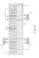
- the number of slots 42 cannot be divided by the number of poles, and a winding of each phase is wound such that a phase belt 17 including three coils and a phase belt 18 including four coils are alternately arranged in a circumferential direction, as shown in FIG. 1 .
- a single-phase armature winding 14 a phase belt 17 including three coils and a phase belt 18 including four coils alternately appear corresponding to each magnetic pole position, as shown in FIG. 2 (The numbers in the square frame shows an example of a slot number.).
- symmetry is not established for each magnetic pole, and a winding coefficient for an even-ordered space harmonic is not zero, as shown in Table 1.
- one ends of the upper and lower coil pieces 15 and 16 are connected in series at a connection side coil end 19a connected to a lead wire of a winding, and other ends of the upper and lower coil pieces 15 and 16 are connected in series at a counter-connection side coil end 19b unconnected to a lead wire of a winding.
- a phase belt 17 including four series coils and a phase belt 18 including five series coils are connected in series, and two sets of circuit including series-connected 4-coil and 5-coil phase belts 17 and 18 is connected in parallel through a lead-out conductor 21 provided at the connection side coil end 19a.
- a phase belt 17x including five coils and a phase belt 18 including six coils alternately appear corresponding to each magnetic pole position.
- symmetry is not established for each magnetic pole, and a winding coefficient for an even-ordered space harmonic is not zero, as shown in Table 1.
- an AC component B 2 ac of a square of a magnetic flux density B corresponding to an electrical frequency is expressed as follows.
- B 2 ac 1 2 ⁇ B 1 2 ⁇ cos 4 ⁇ ⁇ - 2 ⁇ ⁇ t + B 1 ⁇ B a ⁇ 5 cos 8 ⁇ ⁇ + 2 ⁇ ⁇ t + B 1 ⁇ B a ⁇ 7 cos 16 ⁇ ⁇ - ⁇ t + ⁇
- a 4-pole component (2-diameter node mode) appears as a lowest order electromagnetic excitation force.
- a 3-phase 4-pole 2-layer armature winding of a rotating electrical machine A winding of each phase of the armature winding forms a series coil.
- Each series coil includes upper coil pieces and lower coil pieces which are connected each other at a connection side coil end and a counter-connection side coil end, the upper coil pieces and lower coil pieces being placed in 42 or 66 slots provided in an armature core.
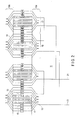
- FIG. 5 is a schematic diagram showing a cross section of an armature of a rotating electrical machine according to a first embodiment.
- FIG. 6 is a developed schematic diagram showing one phase of an armature winding of a rotating electrical machine according to the same embodiment.
- An armature 11 of a rotating electrical machine is provided with 42 slots 13 in an armature core 12 configured by a laminated core, and an armature winding 14 of a 4-pole 3-phase circuit is formed in two layers in slots 13. It is to be noted that in FIGS. 5 and 6 , the numbers in the square frame, which shows an example of a slot number, as are each of the other FIGS.
- An armature winding 14 of each phase includes upper coil pieces 15 placed in an upper part of slots 13, and lower coil pieces 16 placed in a lower part of slots 13. The ends of the upper and lower coil pieces 15 and 16 are connected in series at a connection side coil end 19a connected to a lead wire of a winding, and a counter-connection side coil end 19b opposite along a shaft and unconnected to a lead wire of a winding. Further, an armature winding 14 includes a phase belt 17 including three coils, in which upper and lower coil pieces 15 and 16 are placed in three slots 13 provided in the armature core 12, and a phase belt 18 including four coils, in which upper and lower coil pieces 15 and 16 are placed in four slots 13 provided in the armature core 12.
- FIG. 6 shows an example using a small coil pitch 6 for convenience of viewing. A coil pitch is not to be limited to this value. This is the same in other diagrams.
- FIGS. 6 and 7 two jumper wires 20a are provided per phase at a connection side coil end 19a of each of the phase belts 17 and 18, and four jumper wires 20b are provided per phase at a counter-connection side coil end 19b, and a coil position is indicated by a position from the center of phase in each phase belt.
- a lower coil piece 23 in an outermost position from the center of the phase belt is replaced with a lower coil piece 25 of a 4-coil phase belt of an adjacent different phase.
- a lower coil piece 23 in an innermost position from the center of the phase belt is replaced with a lower coil piece 25 of a 3-coil phase belt of an adjacent different phase.
- the terms “outermost” and “innermost” are intended to mean being “geometrically outermost” and “geometrically innermost.” More specifically, the center of the phase belt corresponds to the slot located at the geometric center. The “outermost” corresponds to the slot farthest from the center of the phase belt, and the “innermost” corresponds to the slot closest to the center of the phase belt.
- the coil pitch corresponds to the number of partitioning walls between the slot of the upper coil piece 15 and the slot of the lower coil piece 16 connected to the upper coil piece 15 through the coil end 19a or 19b. Where the positions of the coil pieces 15 and 16 are indicated by slot numbers, the coil pitch can be regarded as a value representing the difference between the slot number of the upper coil piece 15 and the slot number of the lower coil piece 16.
- a coil pitch is determined to reduce a fifth-order space winding coefficient to prevent deterioration of an induced voltage waveform and rotor surface loss.
- a winding with a coil pitch 9 shown in Table 1 can be selected to reduce fifth-order space winding coefficient to less than 10%.
- Table 2 shows the relationship between a coil pitch and a winding coefficient of each order space in the first embodiment.
- Table 2 Relationship between coil pitch and winding coefficient in first embodiment Coil pitch 10 11 Basic wave winding coefficient 0.9274 0.9271 Second-order space winding coefficient 0.0716 0.0631 Fifth-order space winding coefficient 0.0442 0.0991
- a lower coil piece 23 in an outermost position from the center of the phase belt is replaced with a lower coil piece 25 of a 4-coil phase belt of an adjacent different phase.
- a 4-coil phase belt 18 and a lower coil piece 23 in an innermost position from the center of the phase belt is replaced with a lower coil piece 25 of a 3-coil phase belt of an adjacent different phase.
- a winding coefficient for a second-order space harmonic can be minimized by setting a coil pitch to 11.
- a second-order space harmonic component of a magnetic flux generated by an armature current is reduced.
- a magnetic flux of a second-order space harmonic component acts on a main magnetic flux, and generates a 2-diameter node magnetic excitation force.
- the embodiment is not limited to the configuration shown in the diagrams.
- the same function and effect can be obtained even when upper coil pieces 15 are replaced with lower coil pieces 16 in FIG. 6 , and vice versa, a lower coil piece 23 replaced with a different phase is assumed to be an upper coil piece 22 replaced with a different phase, and a lower coil piece 25 of a different phase is replaced with an upper coil piece of a different phase.
- the function and effect are the same even when a lead-out position is changed from the diagrams.
- two parallel windings are formed by connecting two sets of circuit including 3-coil and 4-coil phase belts 17 and 18 in parallel. The same function and effect can be obtained even when an armature winding is formed by connecting two sets of circuit in series.
- FIG. 8 is a developed schematic diagram showing one phase of an armature winding of a rotating electrical machine according to a second embodiment.
- FIGS. 8 and 9 in a 3-coil phase belt 17, a lower coil piece 23 in an innermost position and a lower coil piece 23 in an outermost position from the center of the phase are replaced with lower coil pieces 25 of a 4-coil phase belt of an adjacent different phase, respectively.
- a 4-coil phase belt 18 in a 4-coil phase belt 18, a lower coil piece 23 in an innermost position and a lower coil piece 23 in an outermost position from the center of the phase belt are replaced with lower coil pieces 25 of a 3-coil phase belt of an adjacent different phase, respectively.
- the configuration except the positions to replace the coil pieces 23 and 25 are the same as those of the first embodiment.
- FIG. 8 shows an example using a small coil pitch 6 for convenience of viewing. A coil pitch is not to be limited to this value.
- Table 3 shows the relationship between a coil pitch and a winding coefficient of each order space in the second embodiment.
- Table 3 Relationship between coil pitch and winding coefficient in second embodiment Coil pitch 10 11 Basic wave winding coefficient 0.9008 0.9008 Second-order space winding coefficient 0.0537 0.0537 Fifth-order space winding coefficient 0.0585 0.0585
- a lower coil piece 23 in an innermost position and a lower coil piece 23 in an outermost position from the center of the phase are replaced with lower coil pieces 25 of a 4-coil phase belt of an adjacent different phase, respectively.
- a 4-coil phase belt 18 in a 4-coil phase belt 18 in a 4-coil phase belt are replaced with lower coil pieces 25 of a 3-coil phase belt of an adjacent different phase, respectively.
- the numbers of jumper wires 20a and 20b at the connection side and counter-connection side coil ends are increased, but a second-order space harmonic component is effectively reduced, and the effect is high over a wide range of coil pitches.
- the embodiment is not limited to the configuration shown in the diagrams.
- the same function and effect can be obtained even when upper coil pieces 15 are replaced with lower coil pieces 16 in FIG. 8 , and vice versa, a lower coil piece 23 replaced with a different phase is assumed to be an upper coil piece 22 replaced with a different phase, and a lower coil piece 25 of a different phase is replaced with an upper coil piece 24 of a different phase.
- the function and effect are the same even when a lead-out position is changed from the diagrams.
- two parallel windings are formed by connecting two sets of circuit including 3-coil and 4-coil phase belts 17 and 18 in parallel. The same function and effect can be obtained even when an armature winding is formed by connecting two sets of circuit in series.
- FIG. 10 is a developed schematic diagram showing one phase of an armature winding of a rotating electrical machine according to a third embodiment.
- the positions to replace the coil pieces 22 to 25 are changed.
- jumper wires 20a are provided per phase at a connection side coil end 19a of each of the phase belts 17 and 18, and eight jumper wires 20b are provided per phase at a counter-connection side coil end 19b.
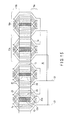
- FIGS. 10 and 11 in a 3-coil phase belt 17, an upper coil piece 22 in an outermost position from the center of a phase is replaced with an upper coil piece 24 of a 4-coil phase belt of an adjacent different phase, and a lower coil piece 23 in an outermost position from the center of the phase belt is replaced with a lower coil piece 25 of a 4-coil phase belt of an adjacent different phase.
- FIG. 10 shows an example using a small coil pitch 6 for convenience of viewing. A coil pitch is not to be limited to this value.
- Table 4 shows the relationship between a coil pitch and a winding coefficient of each order space in the third embodiment.
- Table 4 Relationship between coil pitch and winding coefficient in third embodiment Coil pitch 10 11 Basic wave winding coefficient 0.9010 0.9006 Second-order space winding coefficient 0.0904 0.0791 Fifth-order space winding coefficient 0.0772 0.0846
- an upper coil piece 22 in an outermost position and a lower coil piece 23 in an outermost position from the center of the phase belt are replaced with an upper coil piece 24 and a lower coil piece 25 of a 4-coil phase belt of an adjacent different phase, respectively.
- an upper coil piece 22 in an innermost position and a lower coil piece 23 in an innermost position from the center of the phase belt are replaced with an upper coil piece 24 and a lower coil piece 25 of a 3-coil phase belt of an adjacent different phase, respectively.
- the embodiment is not limited to the configuration shown in the diagrams.
- the function and effect are the same even when a lead-out position is changed from that shown in the diagrams.
- two parallel windings are formed by connecting two sets of circuit including 3-coil and 4-coil phase belts 17 and 18 in parallel. The same function and effect can be obtained even when an armature winding is formed by connecting two sets of circuit in series.
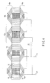
- FIG. 12 is a schematic diagram showing a cross section of an armature winding of a rotating electrical machine according to a fourth embodiment.
- FIG. 13 is a developed schematic diagram showing one phase of an armature winding of a rotating electrical machine according to the same embodiment.
- FIG. 14 is a developed schematic diagram showing a portion of a cross section of an armature of a rotating electrical machine according to the same embodiment.
- An armature 11 of a rotating electrical machine is provided with 66 slots 13x in an armature core 12 configured by a laminated core, and an armature winding 14 of a 4-pole 3-phase circuit is formed in two layers in slots 13x.
- An armature winding 14 of each phase includes upper coil pieces 15 placed in an upper part of slots 13, and lower coil pieces 16 placed in a lower part of slots 13x.
- One ends of the upper and lower coil pieces 15 and 16 are connected in series at a connection side coil end 19a connected to a lead wire of a winding.
- Other ends of the upper and lower coil pieces 15 and 16 are connected in series at a counter-connection side coil end 19b unconnected to a lead wire of a winding.
- the armature winding 14 includes a phase belt 17x including five coils, in which upper and lower coil pieces 15 and 16 are placed in five slots 13x provided in the armature core 12, and a phase belt 18x including six coils, in which upper and lower coil pieces 15 and 16 are placed in six slots 13x provided in the armature core 12.
- FIG. 13 shows an example using a small coil pitch 9 for convenience of viewing.
- a coil pitch is not to be limited to this value. This is the same in diagrams of the following respective embodiments.
- two jumper wires 20a are provided per phase at a connection side coil end 19a of each of the phase belts 17x and 18x, and four jumper wires 20b are provided per phase at a counter-connection side coil end 19b, and a coil position is indicated by a position from the center of phase in each phase belt.
- a 5-coil phase belt 17x a lower coil piece 23 in an innermost position from the center of the phase belt is replaced with a lower coil piece 25 of a 6-coil phase belt of an adjacent different phase.
- a 6-coil phase belt 18x a lower coil piece 23 in an outermost position from the center of the phase belt is replaced with a lower coil piece 25 of a 5-coil phase belt of an adjacent different phase.
- the terms “outermost” and “innermost” are intended to mean being “geometrically outermost” and “geometrically innermost.” More specifically, the center of the phase belt corresponds to the slot located at the geometric center. The “outermost” corresponds to the slot farthest from the center of the phase belt, and the “innermost” corresponds to the slot closest to the center of the phase belt.
- the coil pitch corresponds to the number of partitioning walls between the slot of the upper coil piece 15 and the slot of the lower coil piece 16 connected to the upper coil piece 15 through the coil end 19a or 19b.
- the center of the phase belt corresponds to a value obtained by averaging the slot numbers indicating the coil pieces 15 and 16 of the phase belt, and the coil pitch can be regarded as a value representing the difference between the slot number of the upper coil piece 15 and the slot number of the lower coil piece 16.
- a coil pitch is determined to reduce fifth-order and seventh-order space winding coefficients to prevent deterioration of an induced voltage waveform and rotor surface loss.
- a winding with a coil pitch 13 or 14 shown in Table 1 can be selected to reduce fifth-order and seventh-order space winding coefficients to less than 10%.
- Table 5 shows the relationship between a coil pitch and a winding coefficient of each order space in a conventional example (4-pole 66-slot).
- the values of coil pitches 13-14 are values of the conventional examples shown in Table 1. With respect to the coil pitches other than 13-14, the fifth-order or seventh-order space winding coefficient is not less than 10%. Although such coil pitches are not used in the conventional art, they are included in Table 5, for easy comparison with the data shown in Tables 6-9.
- Table 6 shows the relationship between a coil pitch and a winding coefficient of each order space in the fourth embodiment.
- Table 6 Relationship between coil pitch and winding coefficient in the fourth embodiment Coil pitch 11 12 13 14 15 16 17 Basic wave winding coefficient 0.8196 0.8609 0.8945 0.9199 0.9370 0.9456 0.9456 Second-order space winding coefficient 0.0327 0.0250 0.0166 0.0081 0.0052 0.0129 0.0215 Fifth-order space winding coefficient 0.1398 0.0988 0.0478 0.0584 0.1103 0.1457 0.1515 Seventh-order space winding coefficient 0.0660 0.0913 0.0888 0.0607 0.0465 0.0751 0.0938
- Coil pitches other than 11 to 17 are usually not used, because a coil size becomes too large or small, or a sufficient effect is not obtained.
- a lower coil piece 23 in an innermost position from the center of the phase belt is replaced with a lower coil piece 25 of a 6-coil phase belt of an adjacent different phase.
- a 6-coil phase belt 18x and a lower coil piece 23 in an outermost position from the center of the phase belt is replaced with a lower coil piece 25 of a 5-coil phase belt of an adjacent different phase.
- a winding coefficient for a second-order space harmonic can be minimized by setting a coil pitch to 14.
- a second-order space harmonic component of a magnetic flux generated by an armature current is reduced.
- a magnetic flux of a second-order space harmonic component acts on a main magnetic flux, and generates a 2-diameter node magnetic excitation force.
- the present embodiment is advantageous in that the number of nonstandard connections using jumper wires 20a and 20b is as few as 6 per phase, and the second-order space harmonic component can be reduced to approximately 40% in comparison with the case of coil pitch 14 representing the conventional art.
- the embodiment is not limited to the configuration shown in the diagrams.
- the same function and effect can be obtained even when upper coil pieces 15 in FIG. 13 are assumed to be lower coil pieces 16, and lower coil pieces 16 are assumed to be upper coil pieces 15, an lower coil piece 23 replaced with a different phase is assumed to be a upper coil piece 22 replaced with a different phase, an lower coil piece 25 of a different phase is assumed to be a upper coil piece 24 of a different phase.
- the function and effect are the same even when a lead-out position is changed from the diagrams.
- two parallel windings are formed by connecting two sets of circuit including 5-coil and 6-coil phase belts 17x and 18x in parallel. The same function and effect can be obtained even when an armature winding is formed by connecting two sets of circuit in series.
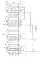
- FIG. 15 is a developed schematic diagram showing one phase of an armature winding of a rotating electrical machine according to the fifth embodiment.
- FIG. 16 is a developed schematic diagram showing a portion of a cross section of an armature of a rotating electrical machine according to the same embodiment.
- FIGS. 13 and 14 elements common to FIGS. 13 and 14 are given the same reference numbers, and a detailed explanation thereof is omitted. Parts different from the fourth embodiment are mainly explained. In each of the embodiments as well, a duplicate explanation is omitted here similarly.
- the coil pieces 22 to 25 replaced with a different phase are changed.
- FIGS. 15 and 16 in a 5-coil phase belt 17x, an upper coil piece 22 in an innermost position and a lower coil piece 23 in an outermost position from the center of the phase are replaced with an upper coil piece 24 and a lower coil piece 25 of a 6-coil phase belt of an adjacent different phase, respectively.
- a 6-coil phase belt 18x an upper coil piece 22 in an innermost position and a lower coil piece 23 in an outermost position from the center of the phase belt are replaced with an upper piece 24 and a lower coil piece 25 of a 5-coil phase belt of an adjacent different phase, respectively.
- the above configuration is the same as those of the fourth embodiment except for the positions to replace the coil pieces 22 to 25.
- Table 7 shows the relationship between a coil pitch and a winding coefficient of each order space in the fifth embodiment.
- Table 7 Relationship between coil pitch and winding coefficient in the fifth embodiment Coil pitch 11 12 13 14 15 16 17 Basic wave winding coefficient 0.7974 0.8376 0.8701 0.8948 0.9114 0.9197 0.9197 Second-order space winding coefficient 0.0339 0.0296 0.0242 0.0179 0.0110 0.0037 0.0037
- Fifth-order space winding coefficient 0.0267 0.0167 0.0029 0.0215 0.0233 0.0300 0.0300 Seventh-order space winding coefficient 0.0636 0.0727 0.0507 0.0070 0.0397 0.0694 0.0694
- fifth-order and seventh-order space winding coefficients are reduced to less than 10% when a coil pitch is 14 to 17 in the fifth embodiment, and a second-order space winding coefficient is lower than a value of coil pitch 13 and 14 in a conventional example shown in Table 5. Therefore, in the fifth embodiment, second-order space harmonic component of a magnetic flux formed by an armature current can be reduced.
- an upper coil piece 22 in an innermost position and a lower coil piece 23 in an outermost position from the center of the phase belt are replaced with an upper coil piece 24 and a lower coil piece 25 of a 6-coil phase belt of an adjacent different phase, respectively.
- an upper coil piece 22 in an innermost position and a lower coil piece 23 in an outermost position from the center of the phase belt are replaced with an upper coil piece 24 and a lower coil piece 25 of a 5-coil phase belt of an adjacent different phase, respectively.
- a winding coefficient for a second-order space harmonic component can be reduced, and a magnetic flux of the second-order space harmonic component is reduced as in the fourth embodiment. Therefore, in the armature winding of the rotating electric machine having 66 slots 4-pole 3-phase, an electromagnetic excitation force of a 4-pole component (2-diameter node mode) induced by a magnetic flux generated by an armature current is decreased, vibration of an armature core is decreased, and the reliability is increased. Specifically, a winding coefficient can be minimized by setting a coil pitch to 16 or 17.
- the fifth embodiment more jumper wires 20a may be required at the connection side coil end, as compared with the fourth embodiment.
- the fifth embodiment is advantageous in that the second-order space harmonic component can be reduced significantly, and the reduction of the second-order space harmonic component can be expected in a wide range where coil pitches are 14-17.
- the number of nonstandard connections using jumper wires 20a may be increased to 8 per phase, but the second-order space harmonic component can be reduced to approximately 20% in comparison with the case of coil pitch 14 representing the conventional art.
- the embodiment is not limited to the configuration shown in the diagrams.
- the function and effect are the same even when a lead-out position is changed from that shown in the diagrams.
- two parallel windings are formed by connecting two sets of circuit including 5-coil and 6-coil phase belts 17x and 18x in parallel. The same function and effect can be obtained even when an armature winding is formed by connecting two sets of circuit in series.
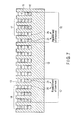
- FIG. 17 is a developed schematic diagram showing one phase of an armature winding of a rotating electrical machine according to the sixth embodiment.
- FIG. 18 is a developed schematic diagram showing a portion of a cross section of an armature of a rotating electrical machine according to the same embodiment.
- the coil pieces 22 to 25 replaced with a different phase are changed.
- jumper wires 20a are provided per phase at a connection side coil end 19a of each of the phase belts 17x and 18x, and eight jumper wires 20b are provided per phase at a counter-connection side coil end 19b.
- FIGS. 17 and 18 in a 5-coil phase belt 17x, an upper coil piece 22 in an innermost position and a lower coil piece 23 in an innermost position from the center of the phase are replaced with an upper coil piece 24 and a lower coil piece 25 of a 6-coil phase belt of an adjacent different phase, respectively.
- an upper coil piece 22 in an outermost position and a lower coil piece 23 in an outermost position from the center of the phase belt are replaced with an upper piece 24 and a lower coil piece 25 of a 5-coil phase belt of an adjacent different phase, respectively.
- the above configuration is the same as those of the fourth embodiment except for the positions to replace the coil pieces 22 to 25.
- Table 8 shows the relationship between a coil pitch and a winding coefficient of each order space in the sixth embodiment.
- Table 8 Relationship between coil pitch and winding coefficient in the sixth embodiment Coil pitch 11 12 13 14 15 16 17 Basic wave winding coefficient 0.8119 0.8529 0.8862 0.9114 0.9284 0.9369 0.9370 Second-order space winding coefficient 0.0196 0.0096 0.0007 0.0110 0.0209 0.0301 0.0381 Fifth-order space winding coefficient 0.1067 0.0770 0.0302 0.0233 0.0717 0.1041 0.1133 Seventh-order space winding coefficient 0.0100 0.0377 0.0492 0.0397 0.0132 0.0189 0.0430
- an upper coil piece 22 in an innermost position and a lower coil piece 23 in an innermost position from the center of the phase belt are replaced with an upper coil piece 24 and a lower coil piece 25 of a 6-coil phase belt of an adjacent different phase, respectively.
- an upper coil piece 22 in an outermost position and a lower coil piece 23 in an outermost position from the center of the phase belt are replaced with an upper coil piece 24 and a lower coil piece 25 of a 5-coil phase belt of an adjacent different phase, respectively.
- the sixth embodiment is advantageous in that the second-order space harmonic component can be reduced significantly, and the reduction of the second-order space harmonic component can be expected in a wide range where coil pitches are 12-14.
- the number of nonstandard connections using jumper wires 20a and 20b may be increased to 12 per phase, but the second-order space harmonic component can be reduced to approximately 5% in comparison with the case of coil pitch 14 representing the conventional art.
- the embodiment is not limited to the configuration shown in the diagrams.
- the function and effect are the same even when a lead-out position is changed from that shown in the diagrams.
- two parallel windings are formed by connecting two sets of circuit including 5-coil and 6-coil phase belts 17x and 18x in parallel. The same function and effect can be obtained even when an armature winding is formed by connecting two sets of circuit in series.
- FIG. 19 is a developed schematic diagram showing one phase of an armature winding of a rotating electrical machine according to the seventh embodiment.
- FIG. 20 is a developed schematic diagram showing a portion of a cross section of an armature of a rotating electrical machine according to the same embodiment.
- the coil pieces 22 and 24 replaced with a different phase are changed.
- jumper wires 20a are provided per phase at a connection side coil end 19a of each of the phase belts 17x and 18x, and eight jumper wires 20b are provided per phase at a counter-connection side coil end 19b.
- FIGS. 19 and 20 in a 5-coil phase belt 17x, an upper coil piece 22 in an innermost position and an upper coil piece 22 in an outermost position from the center of the phase are replaced with upper coil pieces 24 of a 6-coil phase belt of an adjacent different phase, respectively.
- a 6-coil phase belt 18x an upper coil piece 22 in an innermost position and an upper coil piece 22 in an outermost position from the center of the phase belt are replaced with upper pieces 24 of a 5-coil phase belt of an adjacent different phase, respectively.
- the above configuration is the same as those of the fourth embodiment except for the positions to replace the coil pieces 22 and 24.
- Table 9 shows the relationship between a coil pitch and a winding coefficient of each order space in the seventh embodiment.
- an upper coil piece 22 in an innermost position and an upper coil piece 22 in an outermost position from the center of the phase belt are replaced with upper coil pieces 24 of a 6-coil phase belt of an adjacent different phase, respectively.
- an upper coil piece 22 in an innermost position and an upper coil piece 22 in an outermost position from the center of the phase belt are replaced with upper coil pieces 24 of a 5-coil phase belt of an adjacent different phase, respectively.
- the number of nonstandard connections using jumper wires 20a and 20b may be increased to 12 per phase, but the second-order space harmonic component can be reduced to approximately 60% in comparison with the case of coil pitch 14.
- the embodiment is not limited to the configuration shown in the diagrams.
- the same function and effect can be obtained even when upper coil pieces 15 are replaced with lower coil pieces 16 in FIG. 19 , and vice versa, an upper coil piece 22 replaced with a different phase is assumed to be a lower coil piece 23 replaced with a different phase, an upper coil piece 24 of a different phase is replaced with a lower coil piece 25 of a different phase, and lower coil pieces 16 are replaced with upper coil pieces 15.
- the function and effect are the same even when a lead-out position is changed from the diagrams.
- two parallel windings are formed by connecting two sets of circuit including 5-coil and 6-coil phase belts 17x and 18x in parallel. The same function and effect can be obtained even when an armature winding is formed by connecting two sets of circuit in series.
- At least one coil piece of the upper and lower coil pieces is replaced with a coil piece of an adjacent phase.
Landscapes
- Engineering & Computer Science (AREA)
- Power Engineering (AREA)
- Windings For Motors And Generators (AREA)
Applications Claiming Priority (2)
| Application Number | Priority Date | Filing Date | Title |
|---|---|---|---|
| JP2012037893A JP5567047B2 (ja) | 2012-02-23 | 2012-02-23 | 回転電機の電機子巻線 |
| JP2012107565A JP5847645B2 (ja) | 2012-05-09 | 2012-05-09 | 回転電機の電機子巻線 |
Publications (2)
| Publication Number | Publication Date |
|---|---|
| EP2632028A2 true EP2632028A2 (de) | 2013-08-28 |
| EP2632028A3 EP2632028A3 (de) | 2017-09-27 |
Family
ID=47740860
Family Applications (1)
| Application Number | Title | Priority Date | Filing Date |
|---|---|---|---|
| EP13156129.2A Withdrawn EP2632028A3 (de) | 2012-02-23 | 2013-02-21 | Ankerwicklung einer rotierenden elektrischen Maschine |
Country Status (3)
| Country | Link |
|---|---|
| US (1) | US20130221792A1 (de) |
| EP (1) | EP2632028A3 (de) |
| CN (1) | CN103296809B (de) |
Cited By (2)
| Publication number | Priority date | Publication date | Assignee | Title |
|---|---|---|---|---|
| CN103780029A (zh) * | 2014-02-13 | 2014-05-07 | 安徽安凯汽车股份有限公司 | 一种三相双层同心式绕组的绕线方法及三相交流电机 |
| EP3562000A1 (de) * | 2018-04-27 | 2019-10-30 | Wilo Se | Verfahren zum wickeln einer wicklung |
Families Citing this family (5)
| Publication number | Priority date | Publication date | Assignee | Title |
|---|---|---|---|---|
| US8860278B2 (en) * | 2007-07-27 | 2014-10-14 | GM Global Technology Operations LLC | Stator assembly for belt alternator starter motor generator for hybrid vehicles |
| CN104485764A (zh) * | 2014-12-12 | 2015-04-01 | 江西清华泰豪三波电机有限公司 | 一种单匝多圈连绕式成型叠绕组 |
| DE102017208706A1 (de) * | 2016-09-27 | 2018-03-29 | Robert Bosch Gmbh | Stator für eine elektrische Maschine |
| CN114128092B (zh) * | 2019-12-09 | 2024-02-23 | 株式会社东芝 | 旋转电机的电枢绕组以及旋转电机 |
| JP7638065B2 (ja) * | 2020-02-19 | 2025-03-03 | 三菱ジェネレーター株式会社 | 回転電機 |
Family Cites Families (17)
| Publication number | Priority date | Publication date | Assignee | Title |
|---|---|---|---|---|
| US1530466A (en) * | 1924-08-08 | 1925-03-17 | Gen Electric | Induction-motor winding |
| US3408517A (en) * | 1966-02-23 | 1968-10-29 | Gen Electric | Multiple circuit winding patterns for polyphase dynamoelectric machines |
| US4158788A (en) * | 1977-09-27 | 1979-06-19 | Westinghouse Electric Corp. | Special motor windings for the suppression of a specific harmonic by expanding the electrical angle of phase belts |
| JPS59113730A (ja) * | 1982-12-20 | 1984-06-30 | Toshiba Corp | 三相電機子巻線 |
| JPS60190137A (ja) * | 1984-03-08 | 1985-09-27 | Toshiba Corp | 三相電機子巻線 |
| KR940001176B1 (ko) * | 1990-07-19 | 1994-02-16 | 가부시끼가이샤 도시바 | 3상 전기자 권선 |
| JP3351258B2 (ja) * | 1995-09-27 | 2002-11-25 | 株式会社デンソー | 車両用交流発電機 |
| JP3550847B2 (ja) * | 1996-01-24 | 2004-08-04 | 株式会社日立製作所 | 回転電機の電機子巻線パターン |
| US5654602A (en) * | 1996-05-13 | 1997-08-05 | Willyoung; David M. | Generator winding |
| JP3578939B2 (ja) * | 1999-06-04 | 2004-10-20 | 株式会社日立製作所 | 回転電機の巻線方法および回転電機 |
| JP2001238388A (ja) * | 2000-02-25 | 2001-08-31 | Hitachi Ltd | 回転電機の電機子巻線および回転電機 |
| JP2002272074A (ja) * | 2001-03-15 | 2002-09-20 | Moric Co Ltd | 永久磁石式3相交流回転電気機器 |
| US8174159B2 (en) * | 2008-07-17 | 2012-05-08 | Honeywell International, Inc. | Optimized multi-phase armature winding |
| US20100033034A1 (en) * | 2008-08-09 | 2010-02-11 | Chia-Ming Chang | High-Power and High-Torque Step Motor |
| JP5231950B2 (ja) * | 2008-11-13 | 2013-07-10 | 株式会社東芝 | 回転電機の電機子巻線 |
| JP5367436B2 (ja) * | 2009-04-13 | 2013-12-11 | 株式会社東芝 | 回転電機の電機子巻線 |
| JP5710329B2 (ja) * | 2011-03-24 | 2015-04-30 | 株式会社東芝 | 回転電機の電機子巻線 |
-
2013
- 2013-02-21 EP EP13156129.2A patent/EP2632028A3/de not_active Withdrawn
- 2013-02-22 CN CN201310056509.3A patent/CN103296809B/zh not_active Expired - Fee Related
- 2013-02-22 US US13/774,242 patent/US20130221792A1/en not_active Abandoned
Cited By (2)
| Publication number | Priority date | Publication date | Assignee | Title |
|---|---|---|---|---|
| CN103780029A (zh) * | 2014-02-13 | 2014-05-07 | 安徽安凯汽车股份有限公司 | 一种三相双层同心式绕组的绕线方法及三相交流电机 |
| EP3562000A1 (de) * | 2018-04-27 | 2019-10-30 | Wilo Se | Verfahren zum wickeln einer wicklung |
Also Published As
| Publication number | Publication date |
|---|---|
| US20130221792A1 (en) | 2013-08-29 |
| EP2632028A3 (de) | 2017-09-27 |
| CN103296809A (zh) | 2013-09-11 |
| CN103296809B (zh) | 2016-01-13 |
Similar Documents
| Publication | Publication Date | Title |
|---|---|---|
| EP2503673B1 (de) | Ankerwicklung einer rotierenden elektrischen Maschine | |
| EP2632028A2 (de) | Ankerwicklung einer rotierenden elektrischen Maschine | |
| JP5918353B2 (ja) | 回転電機のステータ構造 | |
| US8575809B2 (en) | Stator for an energy converting apparatus and energy converting apparatus using the same | |
| JP5620759B2 (ja) | 電気機械 | |
| JP5438804B2 (ja) | 回転電機 | |
| EP2051350B1 (de) | Ankerwickelschema | |
| US20160190889A1 (en) | Brushed Direct Current Motor | |
| CN106030993A (zh) | 旋转电机 | |
| JP5722568B2 (ja) | モータ | |
| DK2490229T3 (en) | Transformer, amorphous transformer and method of manufacturing the transformer | |
| US7911106B2 (en) | Rotary electric machine | |
| US8362670B2 (en) | Stator and electrical apparatus | |
| CN106849438A (zh) | 旋转电机的电枢绕组 | |
| JP4979605B2 (ja) | 回転電機 | |
| JP5847645B2 (ja) | 回転電機の電機子巻線 | |
| JP4914169B2 (ja) | 回転電機 | |
| JP5567047B2 (ja) | 回転電機の電機子巻線 | |
| JP5704288B1 (ja) | 回転電機の固定子、この固定子を用いた回転電機、及び回転電機の固定子のコイル挿入方法 | |
| CN215934569U (zh) | 三相双层同心式正弦绕组 | |
| CN108352749A (zh) | 旋转电机 | |
| EP2843806B1 (de) | Statorwicklung einer drehenden elektrischen Maschine | |
| TW202322516A (zh) | 具有多層平角繞組之定子及具有多層平角繞組之電機 | |
| US20160190890A1 (en) | Brushed Direct Current Motor |
Legal Events
| Date | Code | Title | Description |
|---|---|---|---|
| PUAI | Public reference made under article 153(3) epc to a published international application that has entered the european phase |
Free format text: ORIGINAL CODE: 0009012 |
|
| 17P | Request for examination filed |
Effective date: 20130221 |
|
| AK | Designated contracting states |
Kind code of ref document: A2 Designated state(s): AL AT BE BG CH CY CZ DE DK EE ES FI FR GB GR HR HU IE IS IT LI LT LU LV MC MK MT NL NO PL PT RO RS SE SI SK SM TR |
|
| AX | Request for extension of the european patent |
Extension state: BA ME |
|
| PUAL | Search report despatched |
Free format text: ORIGINAL CODE: 0009013 |
|
| AK | Designated contracting states |
Kind code of ref document: A3 Designated state(s): AL AT BE BG CH CY CZ DE DK EE ES FI FR GB GR HR HU IE IS IT LI LT LU LV MC MK MT NL NO PL PT RO RS SE SI SK SM TR |
|
| AX | Request for extension of the european patent |
Extension state: BA ME |
|
| RIC1 | Information provided on ipc code assigned before grant |
Ipc: H02K 3/28 20060101AFI20170823BHEP Ipc: H02K 3/12 20060101ALI20170823BHEP |
|
| STAA | Information on the status of an ep patent application or granted ep patent |
Free format text: STATUS: REQUEST FOR EXAMINATION WAS MADE |
|
| STAA | Information on the status of an ep patent application or granted ep patent |
Free format text: STATUS: THE APPLICATION IS DEEMED TO BE WITHDRAWN |
|
| 18D | Application deemed to be withdrawn |
Effective date: 20180328 |