EP2632061A1 - Verfahren und System zur Bereitstellung von mehrstrahliger Abdeckung eines interessierenden Bereichs bei der Mehrstrahlen-Satellitenkommunikation - Google Patents
Verfahren und System zur Bereitstellung von mehrstrahliger Abdeckung eines interessierenden Bereichs bei der Mehrstrahlen-Satellitenkommunikation Download PDFInfo
- Publication number
- EP2632061A1 EP2632061A1 EP12305233.4A EP12305233A EP2632061A1 EP 2632061 A1 EP2632061 A1 EP 2632061A1 EP 12305233 A EP12305233 A EP 12305233A EP 2632061 A1 EP2632061 A1 EP 2632061A1
- Authority
- EP
- European Patent Office
- Prior art keywords
- satellite
- beams
- traffic demand
- interest
- frequency band
- Prior art date
- Legal status (The legal status is an assumption and is not a legal conclusion. Google has not performed a legal analysis and makes no representation as to the accuracy of the status listed.)
- Granted
Links
Images


Classifications
-
- H—ELECTRICITY
- H04—ELECTRIC COMMUNICATION TECHNIQUE
- H04B—TRANSMISSION
- H04B7/00—Radio transmission systems, i.e. using radiation field
- H04B7/14—Relay systems
- H04B7/15—Active relay systems
- H04B7/185—Space-based or airborne stations; Stations for satellite systems
- H04B7/1851—Systems using a satellite or space-based relay
- H04B7/18513—Transmission in a satellite or space-based system
-
- H—ELECTRICITY
- H04—ELECTRIC COMMUNICATION TECHNIQUE
- H04B—TRANSMISSION
- H04B7/00—Radio transmission systems, i.e. using radiation field
- H04B7/14—Relay systems
- H04B7/15—Active relay systems
- H04B7/185—Space-based or airborne stations; Stations for satellite systems
- H04B7/1851—Systems using a satellite or space-based relay
-
- H—ELECTRICITY
- H04—ELECTRIC COMMUNICATION TECHNIQUE
- H04B—TRANSMISSION
- H04B7/00—Radio transmission systems, i.e. using radiation field
- H04B7/14—Relay systems
- H04B7/15—Active relay systems
- H04B7/204—Multiple access
- H04B7/2041—Spot beam multiple access
-
- H—ELECTRICITY
- H04—ELECTRIC COMMUNICATION TECHNIQUE
- H04W—WIRELESS COMMUNICATION NETWORKS
- H04W16/00—Network planning, e.g. coverage or traffic planning tools; Network deployment, e.g. resource partitioning or cells structures
- H04W16/02—Resource partitioning among network components, e.g. reuse partitioning
- H04W16/12—Fixed resource partitioning
Definitions
- the invention relates to a method of providing multi-beam coverage to a Region of Interest in a multi-beam satellite communication system.
- the invention also relates to a satellite communication system implementing said method.
- Multibeam Ka-band satellites for Broad-Band Services allow efficient use of orbit-spectrum and power resources, reducing the cost of the space segment and making the service competitive.
- BBS Broad-Band Services
- One of the major challenges being faced by multibeam BBS networks is how to maximize Operator revenues while coping with a highly uneven traffic demand distribution over the coverage region.
- the basic principle of multibeam satellite communication systems is to cover a specified Region of Interest (ROI) with a number of independent beams. Each independent beam exploits a portion of the available bandwidth. The isolation resulting from antenna directivity and the spatial separation between beams is exploited to re-use the same frequency band in separate beams. The same spectrum can be so re-used multiple times over the ROI.
- frequency re-use is limited by the achievable beam to beam isolation and interference rejection.
- the frequency re-use factor is defined as the number of times that the same frequency band is used. Frequency re-use allows increasing the total capacity of the satellite system without increasing the allocated bandwidth.
- using polarization diversity - i.e. of two orthogonal polarization states allows doubling frequency re-use without increasing interferences.
- the traffic demand (load) experienced by a beam corresponds to the cumulative sum of the spatial traffic demand density - i.e. the traffic demand for unit surface of a small portion of the ROI - over its coverage area (footprint).
- Standard coverage design of multibeam satellite communication systems assumes a uniform traffic demand on which a regular coverage lattice is overlaid (see Figure 1 ).
- a hexagonal lattice of contiguous circular spot beams of equal size is known in prior-art to be the most efficient to guarantee a minimum variation of the satellite antenna gain over a ROI.
- the usefulness of the hexagonal layout can be understood observing that the worst-case (lowest) beam gain corresponds with the triple cross-over points between adjacent beams (i.e. with the hexagon vertices) since they lie at the greatest distance from the beam centre (corresponding to the beam peak gain).
- Simple geometrical reasoning shows that for a same centre-to-vertex distance a regular hexagon has a substantially larger area and requires fewer beams to cover the ROI than any other partition, i.e. based on square or triangular cells.
- Figure 2 shows a frequency/polarization reuse scheme using four different "colours" (i.e. frequency/polarization pairs, e.g. two disjoint frequency bands and two orthogonal polarization states) applied to a hexagonal lattice of cells.
- a known technique for providing flexible RF resource allocation to beams depending on traffic demand consists in using Multiport Amplifiers (MPAs).
- MPAs Multiport Amplifiers
- the main characteristic of a multi-port amplifier is that the signals corresponding to each input port are first split by an input matrix in such a way that the signals of all the beams are amplified by all the high power amplifiers (HPAs) [1]. Therefore equal loading of all the HPAs is achieved independently of the beams power distribution.
- the input matrix generates different relative phases at the HPA inputs.
- the output matrix coherently recombines the signals belonging to each input port to the corresponding output port.
- U.S. patent No. 6,091,934 discloses another technique to ensure dynamic allocation of power to satellite's high power amplifiers to maintain amplifier efficiency and meet peak traffic demands and reduce power consumption during low traffic periods. This can be accomplished adjusting the RF output power from a Travelling Wave Tube Amplifier (TWTA) by changing its bias conditions.
- TWTAs with variable saturated RF power are also known as Flex-TWTAs [2].
- Flex-TWTAs In payload configurations based on Flex-TWTAs each individual TWTA can arbitrarily change (within a range that in current developments is about 3-4 dB) its saturated RF output power to match the traffic demand while maintaining an almost constant efficiency.
- the Flex-TWTAs must be operated such that their aggregated power consumption does not exceed the overall available DC power.
- Flexible Travelling Wave Tube Amplifiers Flex-TWTAs
- MPAs Multi-Port-Amplifiers
- RF switch matrices which allow fixed bandwidth channels to be routed between amplifiers, can also provide a certain degree of flexibility ([3-5]).
- US Pat. 6,173,178 and 6,813,492 disclose a method of generating a non-uniform coverage of a Region of Interest. According to this method, beams of at least two different sizes are used to cover to ROI, larger beams being directed to regions having a lower traffic demand density, and smaller beams being directed to regions having a higher traffic demand density. These documents, however, do not provide any systematic method of designing the coverage, and therefore do not allow optimizing the performances of the communication system.
- the invention aims at solving or attenuating the above-mentioned drawbacks of the priori art.
- An object of the present invention allowing to achieve this aim is a method of providing multi-beam coverage of a Region of Interest in a multi-beam satellite communication system, wherein a non-uniform traffic demand density is defined over said Region of Interest, comprising:
- the inventive method requires a significantly simpler satellite payload, while allowing a similar - or even better - improvement of the overall usable capacity with respect to conventional systems based on a regular coverage of the ROI and on a uniform allocation of resources to the different beams.
- the partitioning of the ROI by non-overlapping cells having a substantially uniform traffic demand allows a simpler, more systematic design, increased flexibility and better performances.
- the present invention is based on the consideration that the traffic load experienced by a beam (i.e. the traffic demand density integrated over the beam coverage area, or "integrated traffic demand”) depends on two factors: the spatial distribution of traffic demand over the region of interest, and the beam's footprint. Given the former beforehand, the latter can be used to control the traffic load by providing a multibeam coverage design such that all beams are evenly loaded within a certain threshold. This concept can be named "Traffic Load Transfer".
- Another object of the present invention is a satellite communication system comprising at least one satellite directing N>1 satellite beams toward a Region of Interest over which a non-uniform traffic demand density is defined, said Region of Interest being partitioned into N non-overlapping cells and each said satellite beam being directed so to provide coverage of a respective cell, characterized in that said Region of Interest is partitioned in such a way that the integrated traffic demand associated to said cells is substantially uniform.
- the partitioning might ensure that the difference between the load (i.e. the traffic demand) of any individual cell and an average load is not greater than 10% - or preferably 1% - of said average load.
- the traffic demand density can be measured or estimated, e.g. based on population density.
- Telecommunication satellites provide a radio relay to certain Region Of Interest (ROI).
- ROI Region Of Interest
- the satellite payload can be equipped a multibeam antenna where each beam of smaller size (i.e. of higher gain) serves a part of the ROI thus allowing frequency reuse.
- Frequency reuse refers to the use of satellite transponder channels on the same frequency/polarization to cover different areas of the ROI which are separated from one another by sufficient distance so that co-channel / co-polar interference is not objectionable. It results in a system capacity increase proportional to the reuse factor.
- Each beam primarily covers an area, defined "cell", where the beam gain is sufficiently high.
- a cell thus signifies the area in which a particular satellite beam is most likely to serve a User Terminal geographically located within the cell.
- the traffic distribution density can be represented by a function f : R 2 ⁇ R providing the traffic demand per unit area as a function of geographical position ( x, y ).
- Its domain ( x , y) ⁇ A corresponds to the bi-dimensional ROI (e.g. represented in latitude and longitude coordinates or in antenna coordinates) as seen from the satellite and its range to the associated traffic demand density (e.g. expressed in megabit per second, Mbps).
- the multibeam coverage corresponds to a partitioning of the domain of definition of f ⁇ (X, Y) in cells filling the ROI with no overlaps and possibly no gaps.
- the geometrical distribution of the cells does not need to be regular, and the cells need not have any particular shape.
- Voronoi diagrams are a simple yet powerful tool that is used in a variety of fields.
- a Voronoi diagram divides the XY plane in a unique way depending on a finite set of generator points ⁇ p 1 ,...,p N ⁇ .
- the i-th cell ( V i ) of the partition corresponds to the set of (x,y) points which are closer to the generator point p i than to any other generator point p j , thus there are as many cells as generator points and every cell is associated to one and only one of them (and vice versa).
- a formal mathematical definition of the Voronoi diagram is found below.
- V p i x
- V i V p i
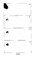
- Voronoi cells are known to be convex polytopes that, when confined within a convex region of interest, tessellate it into convex polygons (see Figure 4 ).
- Each of these polygons would ideally correspond to a beam's footprint, but in practice, due to technological limitations (it may not be possible to achieve such a level of beam shaping), it represents the area in which the gain of a particular satellite beam is high enough so it is most likely to serve a User Terminal geographically located within the polygon.
- the set of generator points conditions the number, size, geometry and position of the resulting cells, therefore controlling it means controlling all properties of the partition. According to the invention, the set of generator points is determined in order to balance the traffic load (although other criteria may also be taken into account).
- the coverage shaping is made through an iterative process in which the different Voronoi generator points are moved until the following condition is met: L ⁇ i - L ⁇ Goal ⁇ L ⁇ Th ⁇ i
- F k , i ⁇ j ⁇ k , ij ⁇ ⁇ k
- ⁇ k,ij ⁇ k (p i , p j , V i , V j , f ⁇ (x, y)) is a generic function.
- F L,i A particular implementation of F L,i that has proved to be effective is detailed below in equation (12). The reason why this particular implementation is proposed is because the numerator resembles — ⁇ L for discrete functions and the denominator follows the inverse square decay law which happens to be usual in nature (e.g. gravitation, Coulomb's law). According to equation (12) F L,i can be expressed in terms of an attractive and repulsive forces. In other words p i is going to be attracted towards those p j that are more loaded than it, but it is going to be pushed away from those p j that are less loaded.
- viscosity is defined as a fluid internal resistance to flow. It is incorporated into the system as resistance to the Voronoi generator points movement. The actual viscosity implementation is done in a per Voronoi cell basis.
- S i be the viscosity-bound displacement vector of p i .
- Figure 10 shows that
- a simple design procedure comprises the following steps ( Figure 20 ):
- the area of the beam footprint can be any increasing function of the area of the convex hull of the traffic demand footprint.
- each of them is assigned a frequency band and polarization accordingly to a uniform partitioning of the frequency and polarization resources between colours.
- the combination of frequency bands/polarizations to be used at system level is four in order to exploit the so-called four colour theorem. Accordingly to this result of topology, given any partition of a plane into contiguous regions no more than four colours are required to colour them so that no two adjacent regions have the same colour. Two regions are called adjacent only if they share a common boundary of non-zero length (i.e. other than a single point). In this particular case each region corresponds to a beam (or its corresponding Voronoi cell) and each "colour" corresponds to a pair (Frequency, Polarization). Hence, if two polarizations are allowed at system level then only 2 frequency bands are needed. On the other hand if only one polarization is used then 4 frequency bands are required. Dual polarized systems are common in practice since they provide double of capacity for the same bandwidth. This leads to four colour frequency plans as the one shown in Figure 12 .
- the four colours frequency and polarization reuse allows sharing high power amplifiers (e.g. travelling wave tube TWTA or solid state power amplifiers SSPA) between two beams reducing the number of HPAs without sacrificing satellite capacity.
- high power amplifiers e.g. travelling wave tube TWTA or solid state power amplifiers SSPA
- Backtracking is a general algorithm for finding solutions to a computational problem incrementally building candidates to the solutions, and abandoning partial candidates ("backtracks") as soon as it is determined that they cannot be completed to a valid solution.
- the backtracking algorithm by itself is blind in the sense that it colours the vertices while traversing the graph. If at some point the current colouring is not FCT compliant it goes a back and tries a different combination of colours.
- This algorithm has some drawbacks. First, it still is a brute force approach and second it does not take into account any kind of variable, except for the colour, to drive the process. To address this latter issue a new heuristic method is presented. This method is described here within the framework of the present invention; however, it can be applied to any case wherein it is necessary to assign a frequency band and a polarization state to a set of satellite beam realizing a non-uniform coverage of a region of interest.
- T ⁇ ⁇ C ⁇ C T so that the CCI experienced by the i-th beam is given by ⁇ ii .
- the colouring problem consists of finding the matrix C that minimizes the expression above given the restriction c ij ⁇ ⁇ 0,1 ⁇ and those stated in (22) and (23). It is important to note that the result will be certainly not unique since from an electromagnetic standpoint one coverage and all its colour permutations (c! in total) are equivalent (i.e. produce the same total CCI).
- V v 11 ⁇ v 1 ⁇ n ⁇ ⁇ ⁇ v n ⁇ 1 ⁇ v nn nxn
- v ij ⁇ 1 if the i - th and j - th beams are neighbours 0 otherwise
- V V T .
- A a 11 ⁇ a 1 ⁇ c ⁇ ⁇ ⁇ a n ⁇ 1 ⁇ a nc nxc
- f ij CCI experienced by the i - th beam at the j - th colour
- the procedure to colour the beams is the following.
- the algorithm selects those rows of F corresponding to uncoloured beams. Simply inspecting these rows allows determining the CCI experimented by the corresponding beam at each colour ( Figure 13 , panel A). If a colour is to be assigned to a beam, the best candidate is the one that, being available, presents the minimum CCI. Hence each uncoloured beam is provisionally assigned, from its set of available colours, the one with the minimum CCI ( Figure 13 , panel B).
- the next step is to decide which beam from this set of provisionally coloured beams is the one to definitively keep its colour. That beam is the one with the highest CCI level ( Figure 13 , panel C - the arrow points towards the selected beam - and panel D). By doing so one can expect that its CCI level will not be significantly increased since its neighbours will not be able to get the same colour and CCI is mainly generated by the closest beams. This way the algorithm tries to minimize the overall system CCI level.
- the process is illustrated by Figure 13 and by equation (32).
- the payload architecture can be based on a set of multibeam passive antennas with a single-feed-per-beam configuration.
- the minimum beamwidth is primarily determined by the reflector diameter and feed dimensions can be used to produce spot beams with different beamwidth.
- the payload architecture can be based on a reduced number (i.e. potentially a single antenna) of multibeam passive antennas in an array-fed configuration (e.g. array-fed-reflector, array-fed-lens or other optical systems fed by a common array) with fixed or reconfigurable (e.g. by means of ferrite microwave control elements) beamforming networks (in particular with lossless high power beamforming network for transmission).
- array-fed configuration e.g. array-fed-reflector, array-fed-lens or other optical systems fed by a common array
- fixed or reconfigurable e.g. by means of ferrite microwave control elements
- the payload architecture can be based on a single transmit and a single receive active antennas with distributed amplification and reconfigurable beamforming.
- the payload architectures based on single-feed-per-beam or fixed beamforming cannot be reconfigured in orbit so that the multibeam layout must be designed having in mind the traffic evolution within the ROI.
- Additional payload flexibility means e.g. flexible-TWTA, multiport-amplifiers, etc.
- flexible-TWTA, multiport-amplifiers, etc. can offer the capability to adapt to traffic variations during the lifetime of the satellite.
- Payload architectures based on reconfigurable beamforming allow to modify the multibeam layout during the satellite lifetime as well as to adapt on a short/medium time scale the coverage to the time-varying traffic distribution.
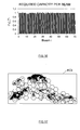
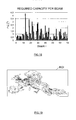
- the usable capacity analysis was made through multidimensional link budget simulations with adaptive coding and modulation. For undertaking the simulations a random set of 2680 ground terminals was generated using the traffic distribution as probability density function (see Figure 19 ).
- each circle represents the antenna half peak gain of a beam (radiation pattern 3dB cut).
- the area of each circle is the same as the one of the convex hull of the traffic demand footprint underneath the Voronoi cell it serves and it is centred at the geometrical centroid (centre-of-mass) of the convex hull.
- hexagonal cells are also served by circular beams. Each beam circumscribes the cell it serves.
- the final layout and frequency plan is shown in Figure 22 according to Figure 12 .
- Circles shown in Figure 21 and Figure 22 are not the radiation diagram itself but rather a mask that any radiation diagram must comply with, thus different compliant radiation patterns can be used. In this particular case two different radiation diagrams were chosen with very satisfactory results.
- the first radiation diagram is the one produced by an aperture in which the amplitude of the electric field follows a Gaussian function. Supposing that the electric field is given by equation (33) then the radiation pattern happens to be another Gaussian function (34).
- the advantage of this kind of apertures is that they have no or very low side lobes, therefore the interference produced to other beams that use the same frequency and polarization is very low.
- the second radiation pattern is an analytical model that corresponds to a more realistic antenna that can be found in a standard telecommunication satellite. Assuming that the amplitude of the electric field on a circular reflector of radius a corresponds to an inverted parabola with certain degree of tapering T (35) then the radiation pattern is given by (36).
- ⁇ p (x) is the lambda function defined by Jahnke and Emde [6] as defined in (37) where J p (x) is the Bessel function of the first kind and order p.
Landscapes
- Engineering & Computer Science (AREA)
- Computer Networks & Wireless Communication (AREA)
- Signal Processing (AREA)
- Physics & Mathematics (AREA)
- Astronomy & Astrophysics (AREA)
- Aviation & Aerospace Engineering (AREA)
- General Physics & Mathematics (AREA)
- Radio Relay Systems (AREA)
Priority Applications (2)
| Application Number | Priority Date | Filing Date | Title |
|---|---|---|---|
| EP12305233.4A EP2632061B1 (de) | 2012-02-27 | 2012-02-27 | Verfahren und System zur Bereitstellung von mehrstrahliger Abdeckung eines interessierenden Bereichs bei der Mehrstrahlen-Satellitenkommunikation |
| US13/778,926 US9654201B2 (en) | 2012-02-27 | 2013-02-27 | Method and a system of providing multi-beam coverage of a region of interest in multi-beam satellite communication |
Applications Claiming Priority (1)
| Application Number | Priority Date | Filing Date | Title |
|---|---|---|---|
| EP12305233.4A EP2632061B1 (de) | 2012-02-27 | 2012-02-27 | Verfahren und System zur Bereitstellung von mehrstrahliger Abdeckung eines interessierenden Bereichs bei der Mehrstrahlen-Satellitenkommunikation |
Publications (2)
| Publication Number | Publication Date |
|---|---|
| EP2632061A1 true EP2632061A1 (de) | 2013-08-28 |
| EP2632061B1 EP2632061B1 (de) | 2020-09-02 |
Family
ID=45812740
Family Applications (1)
| Application Number | Title | Priority Date | Filing Date |
|---|---|---|---|
| EP12305233.4A Active EP2632061B1 (de) | 2012-02-27 | 2012-02-27 | Verfahren und System zur Bereitstellung von mehrstrahliger Abdeckung eines interessierenden Bereichs bei der Mehrstrahlen-Satellitenkommunikation |
Country Status (2)
| Country | Link |
|---|---|
| US (1) | US9654201B2 (de) |
| EP (1) | EP2632061B1 (de) |
Cited By (9)
| Publication number | Priority date | Publication date | Assignee | Title |
|---|---|---|---|---|
| WO2016201139A1 (en) | 2015-06-09 | 2016-12-15 | SEAKR Engineering, Inc. | Leo flexible single axis beamforming |
| WO2017062331A1 (en) * | 2015-10-05 | 2017-04-13 | Space Systems/Loral, Llc | Satellite generating large and small beams separated by beams of medium size to cover regions of different traffic demand |
| GB2563397A (en) * | 2017-06-12 | 2018-12-19 | Inmarsat Global Ltd | Beam layout optimisation |
| CN111262619A (zh) * | 2020-01-20 | 2020-06-09 | 中国科学院计算技术研究所 | 一种多波束卫星资源分配方法及系统 |
| CN114095955A (zh) * | 2021-11-08 | 2022-02-25 | 西安电子科技大学 | 基于凸多边形剖分的地对空覆盖的场景化波束生成方法 |
| CN114785402A (zh) * | 2022-04-07 | 2022-07-22 | 西北工业大学 | 一种低干扰的高通量卫星动态波束跳变方法 |
| CN114926021A (zh) * | 2022-05-20 | 2022-08-19 | 上海交通大学 | 基于成像分割与规划一体化的卫星时序最优任务规划方法 |
| CN115102603A (zh) * | 2022-05-27 | 2022-09-23 | 西北工业大学 | 一种高效低复杂度的宽带通信卫星全局波束跳变方法 |
| CN115483960A (zh) * | 2022-08-23 | 2022-12-16 | 爱浦路网络技术(南京)有限公司 | 低轨卫星的跳波束调度方法、系统、装置及存储介质 |
Families Citing this family (15)
| Publication number | Priority date | Publication date | Assignee | Title |
|---|---|---|---|---|
| TWI503041B (zh) * | 2013-10-17 | 2015-10-01 | Chunghwa Telecom Co Ltd | Applied to Cellular Cellular Exploration Methods for Cellular Mobile Networks |
| US9930091B2 (en) | 2015-02-10 | 2018-03-27 | Viasat, Inc. | Transport path-aware quality of service for mobile communications |
| US20170295578A1 (en) * | 2016-04-06 | 2017-10-12 | Qualcomm Incorporated | Bandwidth expansion in channel coexistence |
| WO2017211430A1 (en) * | 2016-06-10 | 2017-12-14 | European Space Agency | Interference-resilient flexible techniques for payload resource allocation in broadband satellites |
| FR3076137B1 (fr) * | 2017-12-21 | 2019-11-15 | Thales | Procede de couverture multifaisceaux par regroupement de faisceaux elementaires de couleurs differentes, et charge utile de telecommunications pour mettre en oeuvre un tel procede |
| US11212051B2 (en) * | 2018-03-06 | 2021-12-28 | Qualcomm Incorporated | Beam management for autonomous uplink with analog beams |
| CN113056005B (zh) * | 2019-12-26 | 2025-03-25 | 北京三星通信技术研究有限公司 | 波束确定方法、装置、电子设备及计算机可读存储介质 |
| WO2021254607A1 (en) | 2020-06-17 | 2021-12-23 | European Space Agency | Pragmatic solutions for massive mimo for broadband telecommunication systems |
| CN113660025B (zh) * | 2021-07-21 | 2022-08-12 | 中国空间技术研究院 | 一种基于中心频点固定的高通量卫星波束频率调整方法 |
| US20250047363A1 (en) * | 2021-08-20 | 2025-02-06 | European Space Agency | Heuristic radio resource management for massive mimo in satellite broadband communication networks |
| CN113740883B (zh) * | 2021-09-06 | 2024-08-16 | 阳光学院 | 基于多面相控阵的卫星导航干扰测向系统和方法 |
| CN113872653B (zh) * | 2021-09-30 | 2025-04-01 | 重庆两江卫星移动通信有限公司 | 一种基于地球匹配的波束赋形方法 |
| CN115801067B (zh) * | 2022-11-03 | 2025-01-24 | 中国空间技术研究院 | 一种高通量卫星波束覆盖区灵活调整方法 |
| CN115913331B (zh) * | 2022-11-10 | 2025-01-24 | 中国空间技术研究院 | 一种基于回溯搜索的高通量卫星频率计划排布方法 |
| WO2025058411A1 (ko) * | 2023-09-14 | 2025-03-20 | 스페이스맵 주식회사 | 지상국과 통신 위성 간의 무선 통신 간섭 예측 및 회피 시스템 및 방법 |
Citations (4)
| Publication number | Priority date | Publication date | Assignee | Title |
|---|---|---|---|---|
| GB2318947A (en) * | 1996-10-30 | 1998-05-06 | Motorola Inc | Intelligent digital beam forming system responsive to traffic demand |
| US6091934A (en) | 1997-09-02 | 2000-07-18 | Hughes Electronics Corporation | Dynamic power allocation system and method for multi-beam satellite amplifiers |
| EP1050980A1 (de) * | 1999-05-05 | 2000-11-08 | Trw Inc. | Antennenstrahlungsbündelmuster zum Gebrauch bei einer ungleichmässigen Bevölkerungsverteilung |
| US6173178B1 (en) | 1997-12-16 | 2001-01-09 | Trw Inc. | Satellite beam pattern for non-uniform population distribution |
Family Cites Families (3)
| Publication number | Priority date | Publication date | Assignee | Title |
|---|---|---|---|---|
| DE60033350T2 (de) * | 1999-10-15 | 2007-07-12 | Northrop Grumman Corp., Los Angeles | Dynamische Auswahl der Strahlbreite für Vielfachzugriffszellen mit ungleichmässiger Verteilung |
| US20050190991A1 (en) * | 2004-02-27 | 2005-09-01 | Intergraph Software Technologies Company | Forming a single image from overlapping images |
| US20080055153A1 (en) * | 2006-08-29 | 2008-03-06 | Wildblue Communications, Inc. | Network-Access Satellite Communication System |
-
2012
- 2012-02-27 EP EP12305233.4A patent/EP2632061B1/de active Active
-
2013
- 2013-02-27 US US13/778,926 patent/US9654201B2/en active Active
Patent Citations (5)
| Publication number | Priority date | Publication date | Assignee | Title |
|---|---|---|---|---|
| GB2318947A (en) * | 1996-10-30 | 1998-05-06 | Motorola Inc | Intelligent digital beam forming system responsive to traffic demand |
| US6091934A (en) | 1997-09-02 | 2000-07-18 | Hughes Electronics Corporation | Dynamic power allocation system and method for multi-beam satellite amplifiers |
| US6173178B1 (en) | 1997-12-16 | 2001-01-09 | Trw Inc. | Satellite beam pattern for non-uniform population distribution |
| US6813492B1 (en) | 1997-12-16 | 2004-11-02 | Northrop Grumman Corporation | Satellite beam pattern for non-uniform population distribution |
| EP1050980A1 (de) * | 1999-05-05 | 2000-11-08 | Trw Inc. | Antennenstrahlungsbündelmuster zum Gebrauch bei einer ungleichmässigen Bevölkerungsverteilung |
Non-Patent Citations (9)
| Title |
|---|
| A. MALARKY; T. STAJCER; T. JONES; J. DOREY: "A Near-term Solution to Providing Flexibility in Multi-beam Communications Payloads", PROCEEDINGS OF THE 25TH AIAA INTERNATIONAL COMMUNICATIONS SATELLITE CONFERENCE (ICSSC 2007), SEOUL, KOREA, 11 April 2007 (2007-04-11) |
| ANZALCHI J.; HARVERSON M.: "Generic Flexible Payload Technology for Enhancing In-orbit Satellite Payload Flexibility", PROCEEDINGS OF THE 25TH AIAA INTERNATIONAL COMMUNICATIONS SATELLITE CONFERENCE (ICSSC 2007), SEOUL, KOREA, 11 April 2007 (2007-04-11) |
| CHRIS ARNEY ET AL: "Models and metrics of geometric cooperation", WINTER SIMULATION CONFERENCE (WSC), PROCEEDINGS OF THE 2010, IEEE, PISCATAWAY, NJ, USA, 5 December 2010 (2010-12-05), pages 1383 - 1394, XP031842828, ISBN: 978-1-4244-9866-6 * |
| E. JAHNKE; F. EMDE: "Tables of Functions with Formulae and Curves", 1945 |
| LLOYD, S.P.: "Least Squares Quantization in PCM", IEEE TRANSACTIONS ON INFORMATION THEORY, vol. IT-28, March 1982 (1982-03-01), pages 129 - 137, XP008083648, DOI: doi:10.1109/TIT.1982.1056489 |
| M. KHILLA; W. GROSS; H. SCHREIBER; D. LEUCHT: "Flexible Ka-Band LCAMP for In-Orbit Output Power Adjustable MPM", 23RD AIAA INT. COMMUNICATIONS SATELLITE SYSTEMS CONF. (ICSSC), ROME, 2005 |
| MAX, J.: "Quantizing for Minimum Distortion", IRE TRANSACTIONS ON INFORMATION THEORY, vol. IT-6, March 1960 (1960-03-01), pages 7 - 12, XP011217118 |
| P. ANGELETTI; M. LISI: "Multiport Power Amplifiers for Flexible Satellite Antennas and Payloads", MICROWAVE JOURNAL, vol. 53, no. 5, May 2010 (2010-05-01) |
| R. RINALDO; X. MAUFROID; R. CASALEIZ GARCIA: "Non-Uniform Bandwidth and Power Allocation in Multi-Beam Broadband Satellite Systems", PROCEEDINGS OF THE 23RD AIAA INTERNATIONAL COMMUNICATIONS SATELLITE SYSTEMS CONFERENCE (ICSSC 2005), ROME, ITALY, September 2005 (2005-09-01) |
Cited By (21)
| Publication number | Priority date | Publication date | Assignee | Title |
|---|---|---|---|---|
| WO2016201139A1 (en) | 2015-06-09 | 2016-12-15 | SEAKR Engineering, Inc. | Leo flexible single axis beamforming |
| EP3308475A4 (de) * | 2015-06-09 | 2019-01-16 | Seakr Engineering, Inc. | Leo-flexible einachsige strahlformung |
| WO2017062331A1 (en) * | 2015-10-05 | 2017-04-13 | Space Systems/Loral, Llc | Satellite generating large and small beams separated by beams of medium size to cover regions of different traffic demand |
| US9705586B2 (en) | 2015-10-05 | 2017-07-11 | Space Systems/Loral, Llc | Satellite with transition beam size |
| GB2563397A (en) * | 2017-06-12 | 2018-12-19 | Inmarsat Global Ltd | Beam layout optimisation |
| WO2018229468A3 (en) * | 2017-06-12 | 2019-01-17 | Inmarsat Global Limited | BEAM ARRANGEMENT OPTIMIZATION |
| US11133860B2 (en) | 2017-06-12 | 2021-09-28 | Inmarsat Global Limited | Beam layout optimisation |
| US12476699B2 (en) | 2017-06-12 | 2025-11-18 | Inmarsat Global Limited | Beam layout optimisation |
| US11923961B2 (en) | 2017-06-12 | 2024-03-05 | Inmarsat Global Limited | Beam layout optimisation |
| CN111262619A (zh) * | 2020-01-20 | 2020-06-09 | 中国科学院计算技术研究所 | 一种多波束卫星资源分配方法及系统 |
| CN111262619B (zh) * | 2020-01-20 | 2021-04-06 | 中国科学院计算技术研究所 | 一种多波束卫星资源分配方法及系统 |
| CN114095955B (zh) * | 2021-11-08 | 2023-08-18 | 西安电子科技大学 | 基于凸多边形剖分的地对空覆盖的场景化波束生成方法 |
| CN114095955A (zh) * | 2021-11-08 | 2022-02-25 | 西安电子科技大学 | 基于凸多边形剖分的地对空覆盖的场景化波束生成方法 |
| CN114785402B (zh) * | 2022-04-07 | 2024-02-27 | 西北工业大学 | 一种低干扰的高通量卫星动态波束跳变方法 |
| CN114785402A (zh) * | 2022-04-07 | 2022-07-22 | 西北工业大学 | 一种低干扰的高通量卫星动态波束跳变方法 |
| CN114926021B (zh) * | 2022-05-20 | 2023-01-03 | 上海交通大学 | 基于成像分割与规划一体化的卫星时序最优任务规划方法 |
| CN114926021A (zh) * | 2022-05-20 | 2022-08-19 | 上海交通大学 | 基于成像分割与规划一体化的卫星时序最优任务规划方法 |
| CN115102603A (zh) * | 2022-05-27 | 2022-09-23 | 西北工业大学 | 一种高效低复杂度的宽带通信卫星全局波束跳变方法 |
| CN115102603B (zh) * | 2022-05-27 | 2023-11-03 | 西北工业大学 | 一种高效低复杂度的宽带通信卫星全局波束跳变方法 |
| CN115483960A (zh) * | 2022-08-23 | 2022-12-16 | 爱浦路网络技术(南京)有限公司 | 低轨卫星的跳波束调度方法、系统、装置及存储介质 |
| CN115483960B (zh) * | 2022-08-23 | 2023-08-29 | 爱浦路网络技术(南京)有限公司 | 低轨卫星的跳波束调度方法、系统、装置及存储介质 |
Also Published As
| Publication number | Publication date |
|---|---|
| US9654201B2 (en) | 2017-05-16 |
| EP2632061B1 (de) | 2020-09-02 |
| US20130244572A1 (en) | 2013-09-19 |
Similar Documents
| Publication | Publication Date | Title |
|---|---|---|
| EP2632061B1 (de) | Verfahren und System zur Bereitstellung von mehrstrahliger Abdeckung eines interessierenden Bereichs bei der Mehrstrahlen-Satellitenkommunikation | |
| Paris et al. | A genetic algorithm for joint power and bandwidth allocation in multibeam satellite systems | |
| CN107408966B (zh) | 用于适配波束图案的方法、控制系统和通信系统 | |
| US8818440B2 (en) | Apparatus and method for controlling power in distributed multiple input multiple output wireless communication system | |
| US7706787B2 (en) | Multi-beam communication system and method | |
| JP5450827B2 (ja) | 直交偏波を備えたデュアルビーム・アンテナ用の重みベクトルを設計する方法 | |
| Lei et al. | Joint power and carrier allocation for the multibeam satellite downlink with individual SINR constraints | |
| CN110557797B (zh) | 用于运营高通量卫星的方法及系统 | |
| EP3469737B1 (de) | Interferenzbeständige flexible techniken zur nutzlastressourcenzuweisung in breitbandsatelliten | |
| Kyrgiazos et al. | Irregular beam sizes and non-uniform bandwidth allocation in HTS multibeam satellite systems | |
| Angeletti et al. | Traffic balancing multibeam antennas for communication satellites | |
| Roumeliotis et al. | An optimized simple strategy for capacity allocation in satellite systems with smart gateway diversity | |
| Park et al. | Performance analysis of dynamic resource allocation for interference mitigation in integrated satellite and terrestrial systems | |
| Fenech et al. | Satellite Antennas and Digital Payloads for Future Communication Satellites: The quest for efficiencies and greater flexibility | |
| US6831600B1 (en) | Intermodulation suppression for transmit active phased array multibeam antennas with shaped beams | |
| Vidal et al. | Benchmark of MEO multibeam satellite adaptive antenna and payload architectures for broadband systems | |
| Tuzi et al. | Multi-beam analysis of satellite swarm-based antenna arrays for 6G direct-to-cell connectivity | |
| Na et al. | Beamforming and band allocation for satellite and high-altitude platforms cognitive systems | |
| Gallinaro et al. | Next generation interactive S‐band mobile systems: challenges and solutions | |
| Hanna et al. | UAV swarms as amplify-and-forward MIMO relays | |
| Lizarraga et al. | Multibeam satellites performance analysis in non-uniform traffic conditions | |
| Roumeliotis et al. | Capacity allocation mechanisms in high-throughput satellite systems: One-to-many pairings | |
| Abdu et al. | Limits of smart radio resource assignment in GEO satellite communications | |
| Zhang et al. | High-throughput satellite flexibility design and modeling | |
| Icolari et al. | Flexible precoding for mobile satellite system hot spots |
Legal Events
| Date | Code | Title | Description |
|---|---|---|---|
| PUAI | Public reference made under article 153(3) epc to a published international application that has entered the european phase |
Free format text: ORIGINAL CODE: 0009012 |
|
| AK | Designated contracting states |
Kind code of ref document: A1 Designated state(s): AL AT BE BG CH CY CZ DE DK EE ES FI FR GB GR HR HU IE IS IT LI LT LU LV MC MK MT NL NO PL PT RO RS SE SI SK SM TR |
|
| AX | Request for extension of the european patent |
Extension state: BA ME |
|
| 17P | Request for examination filed |
Effective date: 20140226 |
|
| RBV | Designated contracting states (corrected) |
Designated state(s): AL AT BE BG CH CY CZ DE DK EE ES FI FR GB GR HR HU IE IS IT LI LT LU LV MC MK MT NL NO PL PT RO RS SE SI SK SM TR |
|
| STAA | Information on the status of an ep patent application or granted ep patent |
Free format text: STATUS: EXAMINATION IS IN PROGRESS |
|
| 17Q | First examination report despatched |
Effective date: 20180906 |
|
| GRAP | Despatch of communication of intention to grant a patent |
Free format text: ORIGINAL CODE: EPIDOSNIGR1 |
|
| STAA | Information on the status of an ep patent application or granted ep patent |
Free format text: STATUS: GRANT OF PATENT IS INTENDED |
|
| INTG | Intention to grant announced |
Effective date: 20191127 |
|
| GRAJ | Information related to disapproval of communication of intention to grant by the applicant or resumption of examination proceedings by the epo deleted |
Free format text: ORIGINAL CODE: EPIDOSDIGR1 |
|
| STAA | Information on the status of an ep patent application or granted ep patent |
Free format text: STATUS: EXAMINATION IS IN PROGRESS |
|
| INTC | Intention to grant announced (deleted) | ||
| GRAR | Information related to intention to grant a patent recorded |
Free format text: ORIGINAL CODE: EPIDOSNIGR71 |
|
| GRAS | Grant fee paid |
Free format text: ORIGINAL CODE: EPIDOSNIGR3 |
|
| STAA | Information on the status of an ep patent application or granted ep patent |
Free format text: STATUS: GRANT OF PATENT IS INTENDED |
|
| GRAA | (expected) grant |
Free format text: ORIGINAL CODE: 0009210 |
|
| STAA | Information on the status of an ep patent application or granted ep patent |
Free format text: STATUS: THE PATENT HAS BEEN GRANTED |
|
| AK | Designated contracting states |
Kind code of ref document: B1 Designated state(s): AL AT BE BG CH CY CZ DE DK EE ES FI FR GB GR HR HU IE IS IT LI LT LU LV MC MK MT NL NO PL PT RO RS SE SI SK SM TR |
|
| INTG | Intention to grant announced |
Effective date: 20200727 |
|
| REG | Reference to a national code |
Ref country code: GB Ref legal event code: FG4D |
|
| REG | Reference to a national code |
Ref country code: AT Ref legal event code: REF Ref document number: 1310014 Country of ref document: AT Kind code of ref document: T Effective date: 20200915 Ref country code: CH Ref legal event code: EP |
|
| REG | Reference to a national code |
Ref country code: DE Ref legal event code: R096 Ref document number: 602012072079 Country of ref document: DE |
|
| REG | Reference to a national code |
Ref country code: IE Ref legal event code: FG4D |
|
| REG | Reference to a national code |
Ref country code: LT Ref legal event code: MG4D |
|
| PG25 | Lapsed in a contracting state [announced via postgrant information from national office to epo] |
Ref country code: HR Free format text: LAPSE BECAUSE OF FAILURE TO SUBMIT A TRANSLATION OF THE DESCRIPTION OR TO PAY THE FEE WITHIN THE PRESCRIBED TIME-LIMIT Effective date: 20200902 Ref country code: SE Free format text: LAPSE BECAUSE OF FAILURE TO SUBMIT A TRANSLATION OF THE DESCRIPTION OR TO PAY THE FEE WITHIN THE PRESCRIBED TIME-LIMIT Effective date: 20200902 Ref country code: BG Free format text: LAPSE BECAUSE OF FAILURE TO SUBMIT A TRANSLATION OF THE DESCRIPTION OR TO PAY THE FEE WITHIN THE PRESCRIBED TIME-LIMIT Effective date: 20201202 Ref country code: FI Free format text: LAPSE BECAUSE OF FAILURE TO SUBMIT A TRANSLATION OF THE DESCRIPTION OR TO PAY THE FEE WITHIN THE PRESCRIBED TIME-LIMIT Effective date: 20200902 Ref country code: LT Free format text: LAPSE BECAUSE OF FAILURE TO SUBMIT A TRANSLATION OF THE DESCRIPTION OR TO PAY THE FEE WITHIN THE PRESCRIBED TIME-LIMIT Effective date: 20200902 Ref country code: GR Free format text: LAPSE BECAUSE OF FAILURE TO SUBMIT A TRANSLATION OF THE DESCRIPTION OR TO PAY THE FEE WITHIN THE PRESCRIBED TIME-LIMIT Effective date: 20201203 Ref country code: NO Free format text: LAPSE BECAUSE OF FAILURE TO SUBMIT A TRANSLATION OF THE DESCRIPTION OR TO PAY THE FEE WITHIN THE PRESCRIBED TIME-LIMIT Effective date: 20201202 |
|
| REG | Reference to a national code |
Ref country code: NL Ref legal event code: MP Effective date: 20200902 |
|
| REG | Reference to a national code |
Ref country code: AT Ref legal event code: MK05 Ref document number: 1310014 Country of ref document: AT Kind code of ref document: T Effective date: 20200902 |
|
| PG25 | Lapsed in a contracting state [announced via postgrant information from national office to epo] |
Ref country code: PL Free format text: LAPSE BECAUSE OF FAILURE TO SUBMIT A TRANSLATION OF THE DESCRIPTION OR TO PAY THE FEE WITHIN THE PRESCRIBED TIME-LIMIT Effective date: 20200902 Ref country code: RS Free format text: LAPSE BECAUSE OF FAILURE TO SUBMIT A TRANSLATION OF THE DESCRIPTION OR TO PAY THE FEE WITHIN THE PRESCRIBED TIME-LIMIT Effective date: 20200902 Ref country code: LV Free format text: LAPSE BECAUSE OF FAILURE TO SUBMIT A TRANSLATION OF THE DESCRIPTION OR TO PAY THE FEE WITHIN THE PRESCRIBED TIME-LIMIT Effective date: 20200902 |
|
| PG25 | Lapsed in a contracting state [announced via postgrant information from national office to epo] |
Ref country code: SM Free format text: LAPSE BECAUSE OF FAILURE TO SUBMIT A TRANSLATION OF THE DESCRIPTION OR TO PAY THE FEE WITHIN THE PRESCRIBED TIME-LIMIT Effective date: 20200902 Ref country code: RO Free format text: LAPSE BECAUSE OF FAILURE TO SUBMIT A TRANSLATION OF THE DESCRIPTION OR TO PAY THE FEE WITHIN THE PRESCRIBED TIME-LIMIT Effective date: 20200902 Ref country code: PT Free format text: LAPSE BECAUSE OF FAILURE TO SUBMIT A TRANSLATION OF THE DESCRIPTION OR TO PAY THE FEE WITHIN THE PRESCRIBED TIME-LIMIT Effective date: 20210104 Ref country code: NL Free format text: LAPSE BECAUSE OF FAILURE TO SUBMIT A TRANSLATION OF THE DESCRIPTION OR TO PAY THE FEE WITHIN THE PRESCRIBED TIME-LIMIT Effective date: 20200902 Ref country code: EE Free format text: LAPSE BECAUSE OF FAILURE TO SUBMIT A TRANSLATION OF THE DESCRIPTION OR TO PAY THE FEE WITHIN THE PRESCRIBED TIME-LIMIT Effective date: 20200902 Ref country code: CZ Free format text: LAPSE BECAUSE OF FAILURE TO SUBMIT A TRANSLATION OF THE DESCRIPTION OR TO PAY THE FEE WITHIN THE PRESCRIBED TIME-LIMIT Effective date: 20200902 |
|
| PG25 | Lapsed in a contracting state [announced via postgrant information from national office to epo] |
Ref country code: IS Free format text: LAPSE BECAUSE OF FAILURE TO SUBMIT A TRANSLATION OF THE DESCRIPTION OR TO PAY THE FEE WITHIN THE PRESCRIBED TIME-LIMIT Effective date: 20210102 Ref country code: AL Free format text: LAPSE BECAUSE OF FAILURE TO SUBMIT A TRANSLATION OF THE DESCRIPTION OR TO PAY THE FEE WITHIN THE PRESCRIBED TIME-LIMIT Effective date: 20200902 Ref country code: AT Free format text: LAPSE BECAUSE OF FAILURE TO SUBMIT A TRANSLATION OF THE DESCRIPTION OR TO PAY THE FEE WITHIN THE PRESCRIBED TIME-LIMIT Effective date: 20200902 Ref country code: ES Free format text: LAPSE BECAUSE OF FAILURE TO SUBMIT A TRANSLATION OF THE DESCRIPTION OR TO PAY THE FEE WITHIN THE PRESCRIBED TIME-LIMIT Effective date: 20200902 |
|
| REG | Reference to a national code |
Ref country code: DE Ref legal event code: R097 Ref document number: 602012072079 Country of ref document: DE |
|
| PG25 | Lapsed in a contracting state [announced via postgrant information from national office to epo] |
Ref country code: SK Free format text: LAPSE BECAUSE OF FAILURE TO SUBMIT A TRANSLATION OF THE DESCRIPTION OR TO PAY THE FEE WITHIN THE PRESCRIBED TIME-LIMIT Effective date: 20200902 |
|
| PLBE | No opposition filed within time limit |
Free format text: ORIGINAL CODE: 0009261 |
|
| STAA | Information on the status of an ep patent application or granted ep patent |
Free format text: STATUS: NO OPPOSITION FILED WITHIN TIME LIMIT |
|
| 26N | No opposition filed |
Effective date: 20210603 |
|
| PG25 | Lapsed in a contracting state [announced via postgrant information from national office to epo] |
Ref country code: SI Free format text: LAPSE BECAUSE OF FAILURE TO SUBMIT A TRANSLATION OF THE DESCRIPTION OR TO PAY THE FEE WITHIN THE PRESCRIBED TIME-LIMIT Effective date: 20200902 Ref country code: DK Free format text: LAPSE BECAUSE OF FAILURE TO SUBMIT A TRANSLATION OF THE DESCRIPTION OR TO PAY THE FEE WITHIN THE PRESCRIBED TIME-LIMIT Effective date: 20200902 |
|
| PG25 | Lapsed in a contracting state [announced via postgrant information from national office to epo] |
Ref country code: MC Free format text: LAPSE BECAUSE OF FAILURE TO SUBMIT A TRANSLATION OF THE DESCRIPTION OR TO PAY THE FEE WITHIN THE PRESCRIBED TIME-LIMIT Effective date: 20200902 |
|
| REG | Reference to a national code |
Ref country code: BE Ref legal event code: MM Effective date: 20210228 |
|
| PG25 | Lapsed in a contracting state [announced via postgrant information from national office to epo] |
Ref country code: CH Free format text: LAPSE BECAUSE OF NON-PAYMENT OF DUE FEES Effective date: 20210228 Ref country code: LI Free format text: LAPSE BECAUSE OF NON-PAYMENT OF DUE FEES Effective date: 20210228 Ref country code: LU Free format text: LAPSE BECAUSE OF NON-PAYMENT OF DUE FEES Effective date: 20210227 |
|
| PG25 | Lapsed in a contracting state [announced via postgrant information from national office to epo] |
Ref country code: IE Free format text: LAPSE BECAUSE OF NON-PAYMENT OF DUE FEES Effective date: 20210227 |
|
| PG25 | Lapsed in a contracting state [announced via postgrant information from national office to epo] |
Ref country code: BE Free format text: LAPSE BECAUSE OF NON-PAYMENT OF DUE FEES Effective date: 20210228 |
|
| PG25 | Lapsed in a contracting state [announced via postgrant information from national office to epo] |
Ref country code: HU Free format text: LAPSE BECAUSE OF FAILURE TO SUBMIT A TRANSLATION OF THE DESCRIPTION OR TO PAY THE FEE WITHIN THE PRESCRIBED TIME-LIMIT; INVALID AB INITIO Effective date: 20120227 Ref country code: CY Free format text: LAPSE BECAUSE OF FAILURE TO SUBMIT A TRANSLATION OF THE DESCRIPTION OR TO PAY THE FEE WITHIN THE PRESCRIBED TIME-LIMIT Effective date: 20200902 |
|
| PG25 | Lapsed in a contracting state [announced via postgrant information from national office to epo] |
Ref country code: MK Free format text: LAPSE BECAUSE OF FAILURE TO SUBMIT A TRANSLATION OF THE DESCRIPTION OR TO PAY THE FEE WITHIN THE PRESCRIBED TIME-LIMIT Effective date: 20200902 |
|
| PG25 | Lapsed in a contracting state [announced via postgrant information from national office to epo] |
Ref country code: TR Free format text: LAPSE BECAUSE OF FAILURE TO SUBMIT A TRANSLATION OF THE DESCRIPTION OR TO PAY THE FEE WITHIN THE PRESCRIBED TIME-LIMIT Effective date: 20200902 |
|
| PG25 | Lapsed in a contracting state [announced via postgrant information from national office to epo] |
Ref country code: MT Free format text: LAPSE BECAUSE OF FAILURE TO SUBMIT A TRANSLATION OF THE DESCRIPTION OR TO PAY THE FEE WITHIN THE PRESCRIBED TIME-LIMIT Effective date: 20200902 |
|
| PGFP | Annual fee paid to national office [announced via postgrant information from national office to epo] |
Ref country code: GB Payment date: 20260219 Year of fee payment: 15 |
|
| PGFP | Annual fee paid to national office [announced via postgrant information from national office to epo] |
Ref country code: DE Payment date: 20260218 Year of fee payment: 15 |
|
| PGFP | Annual fee paid to national office [announced via postgrant information from national office to epo] |
Ref country code: IT Payment date: 20260224 Year of fee payment: 15 |
|
| PGFP | Annual fee paid to national office [announced via postgrant information from national office to epo] |
Ref country code: FR Payment date: 20260218 Year of fee payment: 15 |