EP2632191A1 - Procédé d'émission d'éléments d'interaction - Google Patents
Procédé d'émission d'éléments d'interaction Download PDFInfo
- Publication number
- EP2632191A1 EP2632191A1 EP12198867.9A EP12198867A EP2632191A1 EP 2632191 A1 EP2632191 A1 EP 2632191A1 EP 12198867 A EP12198867 A EP 12198867A EP 2632191 A1 EP2632191 A1 EP 2632191A1
- Authority
- EP
- European Patent Office
- Prior art keywords
- terminal
- interaction element
- output
- user
- data processing
- Prior art date
- Legal status (The legal status is an assumption and is not a legal conclusion. Google has not performed a legal analysis and makes no representation as to the accuracy of the status listed.)
- Granted
Links
Images


Classifications
-
- H—ELECTRICITY
- H04—ELECTRIC COMMUNICATION TECHNIQUE
- H04W—WIRELESS COMMUNICATION NETWORKS
- H04W4/00—Services specially adapted for wireless communication networks; Facilities therefor
- H04W4/20—Services signaling; Auxiliary data signalling, i.e. transmitting data via a non-traffic channel
-
- G—PHYSICS
- G06—COMPUTING OR CALCULATING; COUNTING
- G06F—ELECTRIC DIGITAL DATA PROCESSING
- G06F3/00—Input arrangements for transferring data to be processed into a form capable of being handled by the computer; Output arrangements for transferring data from processing unit to output unit, e.g. interface arrangements
- G06F3/01—Input arrangements or combined input and output arrangements for interaction between user and computer
- G06F3/048—Interaction techniques based on graphical user interfaces [GUI]
- G06F3/0481—Interaction techniques based on graphical user interfaces [GUI] based on specific properties of the displayed interaction object or a metaphor-based environment, e.g. interaction with desktop elements like windows or icons, or assisted by a cursor's changing behaviour or appearance
- G06F3/04817—Interaction techniques based on graphical user interfaces [GUI] based on specific properties of the displayed interaction object or a metaphor-based environment, e.g. interaction with desktop elements like windows or icons, or assisted by a cursor's changing behaviour or appearance using icons
-
- H—ELECTRICITY
- H04—ELECTRIC COMMUNICATION TECHNIQUE
- H04W—WIRELESS COMMUNICATION NETWORKS
- H04W4/00—Services specially adapted for wireless communication networks; Facilities therefor
- H04W4/18—Information format or content conversion, e.g. adaptation by the network of the transmitted or received information for the purpose of wireless delivery to users or terminals
- H04W4/185—Information format or content conversion, e.g. adaptation by the network of the transmitted or received information for the purpose of wireless delivery to users or terminals by embedding added-value information into content, e.g. geo-tagging
Definitions
- the invention relates to a method for outputting interaction elements on an internet-capable electronic terminal, wherein the terminal is connected to a computer cloud and a user application runs on a central data processing unit in the computer cloud.
- the so-called cloud computing is becoming increasingly important. It uses IT infrastructures from remote computing facilities to operate user applications. With an Internet-enabled electronic device, such as a mobile phone, the user can interact with the user application. On the terminal itself but only a visualization of the user application is running. The main task of the individual terminal is therefore to provide only the user interface. The application-related computational algorithms implemented within the user application are processed on any remote computing devices within that cloud.
- the advantage of this concept lies in the unlimited capacity of data storage and computing power that the cloud can provide the user, regardless of the capacity of the individual terminal.
- the disadvantage of this is that the cloud sends all visualization data over the Internet to the terminal and thus requires and binds high data transmission capacities.
- the possibilities are limited to adapt the external appearance of user applications in the context of the so-called telephone branding to the network or service provider.
- user-specific settings must always be transferred to the cloud, which then adapts the user applications accordingly, in order to take into account the wishes of the customer for special external manifestations.
- cloud computing offers some advantages; However, the shifting of essential competences from the terminal to the remote computer cloud creates the mentioned disadvantages. It is therefore an object of the present invention an improved method for outputting interaction elements in the context of cloud computing in which the disadvantages mentioned above are at least reduced, in particular avoided.
- the object underlying the invention is achieved by a method according to claim 1 and a data processing arrangement according to claim 9.
- the core of the invention lies in the spatial or hardware decoupling between the implementation of the user application and the generation of the interaction elements which serve for communication between the user and the data processing arrangement.
- the basic idea here is that the user application that runs on any data processing unit within the computer cloud ultimately only issues a request to output any suitable interaction element. Although this request may contain information about the content and also about possible states of the interaction element; the actual manifestation of the interaction element is completely determined by locally occurring on the terminal mapping arrangement.
- an interaction element of the type may be a tactile, optical, auditory or olfactory element.
- the information required to build the interaction element is completely stored on the terminal. This now means: via the Internet, the terminal receives the request from the cloud to issue any interaction element with a predetermined content. The terminal itself or the mapping application running on the terminal then decides which interaction element is actually output.
- the constitutional information necessary for this purpose e.g. Image data (.jpg files) for an optical interaction element or audio data (.wav files) for an auditory interaction element are stored on the terminal itself and, unlike the request, are not transmitted in real time over the Internet.
- the advantage lies in the massive savings potential of data transmission volume, since instead of the setup information now only individual data commands are sent which comprise only a tiny fraction of the data volume of the setup information in terms of volume. Furthermore, there are new opportunities for network or service providers in the mobile sector, the terminals themselves despite the use of the Branding cloud computing. The goal is therefore, the cloud, so strictly speaking the remote data processing unit within the computer cloud, although leave the content work, so that the data processing unit decides with the running there user application, which content should be displayed when; in which manifestation, however, then the communication with the user should take place, namely locally decided in the terminal.
- the mapping application runs locally on the terminal.
- An assignment logic that underlies the assignment application then assigns a concrete image, sound, haptic or olfactory element to the request for the output of an interaction element by the user application.
- the assignment logic preferably automatically takes into account the type of input device assigned to the terminal or of the output device assigned to the terminal. If the terminal has, for example, a touch-sensitive screen, then it is very well suited to visualize input elements as apparent keys on the touch-sensitive screen.
- the input element and the output element are each an optical one. If only one microphone is present as the input device and only one loudspeaker is present as the output device, then the voice output offers itself as a request for the input of a voice command. For example, the output element might appear as the following sound file: "Please say OK now, if you agree.” The input element would then be, for example, a voice recognition function that reacts sensitively to the word "OK".
- the interaction means may be known to have different states.
- a button on a screen can be deactivated, activated, operated, selected, displayed in a kind of situation of reflection or much more.
- this is always the same input element, which is displayed in different states.
- Behind each state hides its own structure information that is held locally in the terminal and is provided when needed.
- the appearance may be changed locally by the mapping application on the terminal if the state of the button is to change due to an operation.
- the advantage lies in a significant improvement of reaction times, since the state change can be made locally and thus no data transfer time via the Internet to the central data processing unit and back is required.
- the mapping logic is automatically adjusted as output parameters or input parameters change.
- Such parameters include all conditions with regard to a connected output device or input device. For example, if one output device is replaced by another, the output parameters will inevitably change as well. If, for example, the screen is switched off for interaction and only the loudspeaker is available, the assignment logic must of course be changed in such a way that acoustic user instead of optical interaction elements are output on the basis of the same request by the user application. The user application running in the cloud remains unaffected by such local changes to the terminal.
- the user can also change the assignment logic, at least unconsciously, for example by entering preferences about his preferred interaction elements. Overall, it can result in a significant increase in usability, without affecting the user application on the cloud. Everything can be done locally. However, should the user have his preferences set as part of a user input on a terminal, so it is advantageous if these preferences would be transferable to other devices that are also used by the same user.
- a high-pitched tone is used as the acknowledgment tone.
- the user can change this acknowledgment tone to a low tone.
- change information about user-related changes to the assignment logic is transferred to another device as part of a device update. For this change information can be stored within the cloud.
- the advantage is that the user is still enabled a cross-device uniform user experience. The low acknowledgment tone will then also be used on the other device.
- FIG. 1 the basic structure of a data processing arrangement 10 according to the invention is shown.
- several electronic and intemetrotarye terminals are provided, such as an intemetdresser TV 1 'or an internet-enabled mobile phone 1 ".
- a mouse 4' is represented as representative of further input means.
- the mouse 4 ' can be connected to the television 1' via a local data line, for example a radio link 5.
- the mobile telephone 1 " has a virtual keyboard 4" as input means which can be read on the touch-sensitive screen 6 "of the mobile telephone 1". is constructed.
- the terminals 1 are connected to a computer cloud 8.
- a computer cloud 8 at least one central data processing unit, in particular a server 3, is provided on which a user application runs. That means: the actual application logic, i. the linking of logical functions within the application, run on the server 3.
- the server 3 then sends over the internet 2 only output information to the terminals 1, the terminals 1 then being e.g. serve as a screen.
- the essential content operations do not take place on the terminals 1 but on the server 3, with the exception of those operations which are required for the concrete appearance of interaction elements.
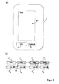
- FIG. 2 For example, the screen 6 "of the mobile phone 1" is shown.
- two controls in the form of softkeys are optical input elements.
- Such input element can assume different states.
- FIG. 2b a flow order of possible different states of the screen button 7 shown.
- 7 1 shows the screen key in an active state that signals the availability of the key.
- the background color can be white, for example. In this active state, operation is not possible by mouse-click or finger-touch.
- the control element 7 1 is not selected, however, so that pressing the return key alone does not actuate the screen key 7.
- 7 2 shows the activated and selected screen key. Pressing the button is now possible, in addition to the mouse click or finger pressure, by simply pressing the return key.
- Opposite the screen button 7 1 is a graphical delimitation, for example, over a stronger frame or by a darker color, for example, a light gray tone (indicated by dots) given.
- Fig. 3 shows the on-screen button in a state when it is apparently depressed by, for example, a mouse click and finger pressure. Compared to the screen button in state 7 2 or 7 1 , this is visualized by edges of different thickness, which should simulate a shift in the room. Further, a small circle circumscribes the area where the finger pointer icon or a mouse pointer touches the on-screen button, thereby giving the user feedback that he is now pressing the button. An even stronger hue is used than at 7 2 , for example a dark gray tone, symbolized by the shading.
- Figure 4 shows the on-screen button after the user seemsingly releases the button, ie, removes the finger from the touchpad or releases the mouse button. It is again changed to the color corresponding to 7 2 . The apparent shift in space disappears. The circle around the apparent point of contact is now larger than in 7 3 .
- 7 5 shows the state when the user input is now validated.
- 7 6 shows a state after the validation is complete.
- the execution of the triggered by input command which is indicated by the display 7 7 of the screen button.
- the completion of the execution is visualized by the screen key 7 8 .
- the different states 7 5 to 7 8 are visualized by different circular symbols on the screen buttons.
- further optical delimitations, such as different background colors can be provided.
- the screen key can be very complex in terms of graphics, and in particular instead of the word "button” any image (for example, a photograph in the form of a .jpg file).
- states 7 1 and 7 2 the user is generally offered something on the basis of the corresponding interaction element 7.
- the states 7 3 and 7 4 the user is fundamentally informed, on the basis of the corresponding interaction element 7, that the system is receiving a user input.
- the states 7 5 and 7 6 the user is fundamentally informed, on the basis of the corresponding interaction element 7, that the system processes the user input.
- the states 7 7 and 7 8 the user is fundamentally informed, on the basis of the corresponding interaction element 7, that the system is carrying out the instruction initiated with the user input.
- such an on-screen button may also have other states associated with the o.g. States can also be combined. In principle, a distinction can be made between an active state and an unavailable state. Furthermore, in each of the states shown, the screen element can be assigned a symbol 9 which is intended to attract the attention of the user.
- the different states do not have to differ from one another by optical features. It could e.g. be provided that each time a change from one of the states to the next state, a different acoustic signal is output.
- the invention now goes a different way by a new division of computing power between server 3 and terminal 1 is made.
- the application logic continues to run on the server 3; the generation of the image information or other information for generating interaction elements, runs separately on the terminal 1 from.
- the server will only prompt 12 ( FIG. 3 ) issued to the terminal via the Internet 2, which states, for example: "Issue an activated but not selected acknowledgment to confirm an operation.”
- the mapping application selects the screen key 7 4 based on the mapping logic FIG. 2b off, confirming the key press input.
- the image information required to construct this screen button that is, the construction information, is stored in the terminal 1. This means that the image information is not transmitted over the Internet. It can be seen that this results in enormous savings potential for data volumes that have to be transported over the Internet.
- the request for the generation of the screen key 7 2 off FIG. 2a is sufficient, can be understood by another terminal as a request to issue a completely different interaction element.
- essentially the same request to acknowledge instead of by issuing the key 7 2 also by a voice output
- the request for this voice output issued by the server 3 and the request for the output of the key 7 2 are completely identical, which means that the server 3, apart from the condition specification, has no influence on how his request to issue an interaction element on the terminal 1 is finally executed.
- connection logic can automatically be adapted by connecting new input devices.
- FIG. 3 a flow chart for carrying out the method according to the invention is shown.
- the user application runs on the server 3 arranged there.
- the user application sends over the Internet 2 output prompts 12 to the terminal 1.
- the output request 12 include state identification information 13, based on which an interaction element, different states are specified.
- the mapping application 14 runs, accessing the mapping logic 15.
- a concrete input or output element to be output is selected.
- information about the input means 4 or output means 6 connected to the terminal as well as the status identification 13 serve as input variables for the assignment logic.
- user preferences can also serve as input variables.
- a concrete input element 7 is now selected, for example a visual input means 7 "".
- the state identification information may specify that the element is deactivated. Then the picture element 7 1 "" is selected. If the status identification specification requires that an active element be output, then, for example, the picture element 7 2 "" can be selected. Information about the selected interaction element 7 is then passed from the mapping logic 15 to the mapping application 14 or generated within the mapping application. An output instruction 16 then takes place on the screen 6 or on corresponding other output devices. On the screen 6 will then output a picture element that represents the screen button 7 2 "".
Landscapes
- Engineering & Computer Science (AREA)
- Computer Networks & Wireless Communication (AREA)
- Signal Processing (AREA)
- General Engineering & Computer Science (AREA)
- Theoretical Computer Science (AREA)
- Human Computer Interaction (AREA)
- Physics & Mathematics (AREA)
- General Physics & Mathematics (AREA)
- User Interface Of Digital Computer (AREA)
Applications Claiming Priority (1)
| Application Number | Priority Date | Filing Date | Title |
|---|---|---|---|
| DE102011122491A DE102011122491A1 (de) | 2011-12-29 | 2011-12-29 | Verfahren zum Ausgeben von Interaktionselementen |
Publications (2)
| Publication Number | Publication Date |
|---|---|
| EP2632191A1 true EP2632191A1 (fr) | 2013-08-28 |
| EP2632191B1 EP2632191B1 (fr) | 2018-02-21 |
Family
ID=47594419
Family Applications (1)
| Application Number | Title | Priority Date | Filing Date |
|---|---|---|---|
| EP12198867.9A Active EP2632191B1 (fr) | 2011-12-29 | 2012-12-21 | Procédé d'émission d'éléments d'interaction |
Country Status (2)
| Country | Link |
|---|---|
| EP (1) | EP2632191B1 (fr) |
| DE (1) | DE102011122491A1 (fr) |
Cited By (1)
| Publication number | Priority date | Publication date | Assignee | Title |
|---|---|---|---|---|
| WO2019057643A2 (fr) | 2017-09-16 | 2019-03-28 | Kairos Capital S.A. | Dispositif de diffusion de substances volatiles et cartouche comprenant des capsules de substances volatiles parfumantes apte a etre mise en oeuvre avec un tel dispositif ou tout autre dispositif comprenant un actionneur mecanique ou vibratoire de capsules |
Citations (3)
| Publication number | Priority date | Publication date | Assignee | Title |
|---|---|---|---|---|
| EP2226719A1 (fr) * | 2009-03-05 | 2010-09-08 | France Telecom | Interface utilisateur pour le rendu d'un profil utilisateur |
| US20100229082A1 (en) * | 2005-09-21 | 2010-09-09 | Amit Karmarkar | Dynamic context-data tag cloud |
| WO2011135352A1 (fr) * | 2010-04-26 | 2011-11-03 | Hu-Do Limited | Dispositif informatique utilisable pour travailler conjointement avec un dispositif électronique compagnon |
Family Cites Families (1)
| Publication number | Priority date | Publication date | Assignee | Title |
|---|---|---|---|---|
| US8078691B2 (en) * | 2009-08-26 | 2011-12-13 | Microsoft Corporation | Web page load time prediction and simulation |
-
2011
- 2011-12-29 DE DE102011122491A patent/DE102011122491A1/de not_active Ceased
-
2012
- 2012-12-21 EP EP12198867.9A patent/EP2632191B1/fr active Active
Patent Citations (3)
| Publication number | Priority date | Publication date | Assignee | Title |
|---|---|---|---|---|
| US20100229082A1 (en) * | 2005-09-21 | 2010-09-09 | Amit Karmarkar | Dynamic context-data tag cloud |
| EP2226719A1 (fr) * | 2009-03-05 | 2010-09-08 | France Telecom | Interface utilisateur pour le rendu d'un profil utilisateur |
| WO2011135352A1 (fr) * | 2010-04-26 | 2011-11-03 | Hu-Do Limited | Dispositif informatique utilisable pour travailler conjointement avec un dispositif électronique compagnon |
Cited By (1)
| Publication number | Priority date | Publication date | Assignee | Title |
|---|---|---|---|---|
| WO2019057643A2 (fr) | 2017-09-16 | 2019-03-28 | Kairos Capital S.A. | Dispositif de diffusion de substances volatiles et cartouche comprenant des capsules de substances volatiles parfumantes apte a etre mise en oeuvre avec un tel dispositif ou tout autre dispositif comprenant un actionneur mecanique ou vibratoire de capsules |
Also Published As
| Publication number | Publication date |
|---|---|
| DE102011122491A1 (de) | 2013-07-04 |
| EP2632191B1 (fr) | 2018-02-21 |
Similar Documents
| Publication | Publication Date | Title |
|---|---|---|
| DE102006021400B4 (de) | Verfahren und Vorrichtung zum Bereitstellen eines einem dargestellten Symbol zugeordneten Auswahlmenüs | |
| DE102007061993B4 (de) | Mobiles Endgerät mit einer Anzeigeeinheit sowie Anzeigeverfahren für ein mobiles Endgerät | |
| CN100495914C (zh) | 图形均衡器的控制器 | |
| CN114237399B (zh) | 触觉反馈方法、装置、介质、设备 | |
| DE102017121758A1 (de) | Intelligente Assistenz für wiederholte Aktionen | |
| DE102022119403A1 (de) | Verfahren und vorrichtungen, um private verbale nebengespräche bei virtuellen sitzungen zu ermöglichen | |
| DE102012009429A1 (de) | Verfahren zur Fernkonfiguration eines Fahrzeugs durch Visualisierung der Fahrzeugbedienung, sowie Endgerät und Fahrzeug hierfür | |
| DE112020007827T5 (de) | Auswählbare bedienelemente für interaktive sprachantwortsysteme | |
| EP1191466A1 (fr) | Application graphique interactive configurable | |
| WO2024179862A1 (fr) | Système de commande multimodal à rétroaction adaptative pour véhicule | |
| EP2632191B1 (fr) | Procédé d'émission d'éléments d'interaction | |
| DE102008049396A1 (de) | Hörgerät-Einstellvorrichtung, Hörgerät und Programm | |
| DE102008041581A1 (de) | Verfahren zum Ausführen von Zielprogrammen mittels Schnelltastenkombinationen | |
| CN106354273B (zh) | 一种操控智能设备的方法及智能设备 | |
| DE102006021376A1 (de) | Verfahren und Vorrichtung zum Bereitstellen von angepassten Kommunikationsfenstern zur Kommunikation mit einem Kommunikationspartner in einer Anwendung auf einem Endgerät eines Benutzers | |
| CN118413507A (zh) | 会话处理方法及装置 | |
| CN118051690A (zh) | 一种可自定义前端页面主题颜色的方法和电子设备 | |
| CN117271030A (zh) | 原型界面的设计方法、装置、存储介质及终端设备 | |
| DE68925089T2 (de) | Arbeitsstation für ein Rechnersystem mit einem Abbildungselement, einem Eingabesystem und einem Audiokommunikationssystem sowie Rechnersystem mit derartigen Arbeitsstationen | |
| DE60002973T2 (de) | Methode zur Auswählen, Bearbeiten und Spielen einer komplexen Tonmeldung | |
| JP7174506B2 (ja) | 情報処理装置 | |
| EP2285626B1 (fr) | Système de communication et procédé de communication entre des dispositifs de communication et au moins un utilisateur d un système de communication | |
| DE102020129601A1 (de) | Verfahren zur steuerung von prozessen mittels einer sprachbefehlseingabe | |
| DE102009059140A1 (de) | Verfahren zur Integration einer Komponente in ein Informationssystem eines Fahrzeugs | |
| DE69325701T2 (de) | Verfahren und System zum Verwenden eines mit einem Datenverarbeitungssystem verbundenen Telephons für die Emulation einer graphischen Eingabevorrichtung |
Legal Events
| Date | Code | Title | Description |
|---|---|---|---|
| PUAI | Public reference made under article 153(3) epc to a published international application that has entered the european phase |
Free format text: ORIGINAL CODE: 0009012 |
|
| AK | Designated contracting states |
Kind code of ref document: A1 Designated state(s): AL AT BE BG CH CY CZ DE DK EE ES FI FR GB GR HR HU IE IS IT LI LT LU LV MC MK MT NL NO PL PT RO RS SE SI SK SM TR |
|
| AX | Request for extension of the european patent |
Extension state: BA ME |
|
| 17P | Request for examination filed |
Effective date: 20140128 |
|
| RBV | Designated contracting states (corrected) |
Designated state(s): AL AT BE BG CH CY CZ DE DK EE ES FI FR GB GR HR HU IE IS IT LI LT LU LV MC MK MT NL NO PL PT RO RS SE SI SK SM TR |
|
| 17Q | First examination report despatched |
Effective date: 20161207 |
|
| GRAP | Despatch of communication of intention to grant a patent |
Free format text: ORIGINAL CODE: EPIDOSNIGR1 |
|
| INTG | Intention to grant announced |
Effective date: 20171027 |
|
| GRAS | Grant fee paid |
Free format text: ORIGINAL CODE: EPIDOSNIGR3 |
|
| GRAA | (expected) grant |
Free format text: ORIGINAL CODE: 0009210 |
|
| AK | Designated contracting states |
Kind code of ref document: B1 Designated state(s): AL AT BE BG CH CY CZ DE DK EE ES FI FR GB GR HR HU IE IS IT LI LT LU LV MC MK MT NL NO PL PT RO RS SE SI SK SM TR |
|
| REG | Reference to a national code |
Ref country code: GB Ref legal event code: FG4D Free format text: NOT ENGLISH |
|
| REG | Reference to a national code |
Ref country code: CH Ref legal event code: EP |
|
| REG | Reference to a national code |
Ref country code: AT Ref legal event code: REF Ref document number: 972977 Country of ref document: AT Kind code of ref document: T Effective date: 20180315 |
|
| REG | Reference to a national code |
Ref country code: IE Ref legal event code: FG4D Free format text: LANGUAGE OF EP DOCUMENT: GERMAN |
|
| REG | Reference to a national code |
Ref country code: DE Ref legal event code: R096 Ref document number: 502012012183 Country of ref document: DE |
|
| REG | Reference to a national code |
Ref country code: NL Ref legal event code: MP Effective date: 20180221 |
|
| REG | Reference to a national code |
Ref country code: LT Ref legal event code: MG4D |
|
| PG25 | Lapsed in a contracting state [announced via postgrant information from national office to epo] |
Ref country code: LT Free format text: LAPSE BECAUSE OF FAILURE TO SUBMIT A TRANSLATION OF THE DESCRIPTION OR TO PAY THE FEE WITHIN THE PRESCRIBED TIME-LIMIT Effective date: 20180221 Ref country code: NL Free format text: LAPSE BECAUSE OF FAILURE TO SUBMIT A TRANSLATION OF THE DESCRIPTION OR TO PAY THE FEE WITHIN THE PRESCRIBED TIME-LIMIT Effective date: 20180221 Ref country code: FI Free format text: LAPSE BECAUSE OF FAILURE TO SUBMIT A TRANSLATION OF THE DESCRIPTION OR TO PAY THE FEE WITHIN THE PRESCRIBED TIME-LIMIT Effective date: 20180221 Ref country code: CY Free format text: LAPSE BECAUSE OF FAILURE TO SUBMIT A TRANSLATION OF THE DESCRIPTION OR TO PAY THE FEE WITHIN THE PRESCRIBED TIME-LIMIT Effective date: 20180221 Ref country code: ES Free format text: LAPSE BECAUSE OF FAILURE TO SUBMIT A TRANSLATION OF THE DESCRIPTION OR TO PAY THE FEE WITHIN THE PRESCRIBED TIME-LIMIT Effective date: 20180221 Ref country code: NO Free format text: LAPSE BECAUSE OF FAILURE TO SUBMIT A TRANSLATION OF THE DESCRIPTION OR TO PAY THE FEE WITHIN THE PRESCRIBED TIME-LIMIT Effective date: 20180521 Ref country code: HR Free format text: LAPSE BECAUSE OF FAILURE TO SUBMIT A TRANSLATION OF THE DESCRIPTION OR TO PAY THE FEE WITHIN THE PRESCRIBED TIME-LIMIT Effective date: 20180221 |
|
| PG25 | Lapsed in a contracting state [announced via postgrant information from national office to epo] |
Ref country code: LV Free format text: LAPSE BECAUSE OF FAILURE TO SUBMIT A TRANSLATION OF THE DESCRIPTION OR TO PAY THE FEE WITHIN THE PRESCRIBED TIME-LIMIT Effective date: 20180221 Ref country code: SE Free format text: LAPSE BECAUSE OF FAILURE TO SUBMIT A TRANSLATION OF THE DESCRIPTION OR TO PAY THE FEE WITHIN THE PRESCRIBED TIME-LIMIT Effective date: 20180221 Ref country code: RS Free format text: LAPSE BECAUSE OF FAILURE TO SUBMIT A TRANSLATION OF THE DESCRIPTION OR TO PAY THE FEE WITHIN THE PRESCRIBED TIME-LIMIT Effective date: 20180221 Ref country code: BG Free format text: LAPSE BECAUSE OF FAILURE TO SUBMIT A TRANSLATION OF THE DESCRIPTION OR TO PAY THE FEE WITHIN THE PRESCRIBED TIME-LIMIT Effective date: 20180521 Ref country code: GR Free format text: LAPSE BECAUSE OF FAILURE TO SUBMIT A TRANSLATION OF THE DESCRIPTION OR TO PAY THE FEE WITHIN THE PRESCRIBED TIME-LIMIT Effective date: 20180522 |
|
| PG25 | Lapsed in a contracting state [announced via postgrant information from national office to epo] |
Ref country code: MT Free format text: LAPSE BECAUSE OF FAILURE TO SUBMIT A TRANSLATION OF THE DESCRIPTION OR TO PAY THE FEE WITHIN THE PRESCRIBED TIME-LIMIT Effective date: 20180221 |
|
| PG25 | Lapsed in a contracting state [announced via postgrant information from national office to epo] |
Ref country code: AL Free format text: LAPSE BECAUSE OF FAILURE TO SUBMIT A TRANSLATION OF THE DESCRIPTION OR TO PAY THE FEE WITHIN THE PRESCRIBED TIME-LIMIT Effective date: 20180221 Ref country code: RO Free format text: LAPSE BECAUSE OF FAILURE TO SUBMIT A TRANSLATION OF THE DESCRIPTION OR TO PAY THE FEE WITHIN THE PRESCRIBED TIME-LIMIT Effective date: 20180221 Ref country code: EE Free format text: LAPSE BECAUSE OF FAILURE TO SUBMIT A TRANSLATION OF THE DESCRIPTION OR TO PAY THE FEE WITHIN THE PRESCRIBED TIME-LIMIT Effective date: 20180221 Ref country code: PL Free format text: LAPSE BECAUSE OF FAILURE TO SUBMIT A TRANSLATION OF THE DESCRIPTION OR TO PAY THE FEE WITHIN THE PRESCRIBED TIME-LIMIT Effective date: 20180221 Ref country code: IT Free format text: LAPSE BECAUSE OF FAILURE TO SUBMIT A TRANSLATION OF THE DESCRIPTION OR TO PAY THE FEE WITHIN THE PRESCRIBED TIME-LIMIT Effective date: 20180221 |
|
| REG | Reference to a national code |
Ref country code: DE Ref legal event code: R097 Ref document number: 502012012183 Country of ref document: DE |
|
| PG25 | Lapsed in a contracting state [announced via postgrant information from national office to epo] |
Ref country code: SK Free format text: LAPSE BECAUSE OF FAILURE TO SUBMIT A TRANSLATION OF THE DESCRIPTION OR TO PAY THE FEE WITHIN THE PRESCRIBED TIME-LIMIT Effective date: 20180221 Ref country code: SM Free format text: LAPSE BECAUSE OF FAILURE TO SUBMIT A TRANSLATION OF THE DESCRIPTION OR TO PAY THE FEE WITHIN THE PRESCRIBED TIME-LIMIT Effective date: 20180221 Ref country code: DK Free format text: LAPSE BECAUSE OF FAILURE TO SUBMIT A TRANSLATION OF THE DESCRIPTION OR TO PAY THE FEE WITHIN THE PRESCRIBED TIME-LIMIT Effective date: 20180221 Ref country code: CZ Free format text: LAPSE BECAUSE OF FAILURE TO SUBMIT A TRANSLATION OF THE DESCRIPTION OR TO PAY THE FEE WITHIN THE PRESCRIBED TIME-LIMIT Effective date: 20180221 |
|
| PLBE | No opposition filed within time limit |
Free format text: ORIGINAL CODE: 0009261 |
|
| STAA | Information on the status of an ep patent application or granted ep patent |
Free format text: STATUS: NO OPPOSITION FILED WITHIN TIME LIMIT |
|
| 26N | No opposition filed |
Effective date: 20181122 |
|
| PG25 | Lapsed in a contracting state [announced via postgrant information from national office to epo] |
Ref country code: SI Free format text: LAPSE BECAUSE OF FAILURE TO SUBMIT A TRANSLATION OF THE DESCRIPTION OR TO PAY THE FEE WITHIN THE PRESCRIBED TIME-LIMIT Effective date: 20180221 |
|
| REG | Reference to a national code |
Ref country code: CH Ref legal event code: PL |
|
| PG25 | Lapsed in a contracting state [announced via postgrant information from national office to epo] |
Ref country code: LU Free format text: LAPSE BECAUSE OF NON-PAYMENT OF DUE FEES Effective date: 20181221 Ref country code: MC Free format text: LAPSE BECAUSE OF FAILURE TO SUBMIT A TRANSLATION OF THE DESCRIPTION OR TO PAY THE FEE WITHIN THE PRESCRIBED TIME-LIMIT Effective date: 20180221 |
|
| REG | Reference to a national code |
Ref country code: IE Ref legal event code: MM4A |
|
| REG | Reference to a national code |
Ref country code: BE Ref legal event code: MM Effective date: 20181231 |
|
| PG25 | Lapsed in a contracting state [announced via postgrant information from national office to epo] |
Ref country code: IE Free format text: LAPSE BECAUSE OF NON-PAYMENT OF DUE FEES Effective date: 20181221 |
|
| PG25 | Lapsed in a contracting state [announced via postgrant information from national office to epo] |
Ref country code: BE Free format text: LAPSE BECAUSE OF NON-PAYMENT OF DUE FEES Effective date: 20181231 |
|
| PG25 | Lapsed in a contracting state [announced via postgrant information from national office to epo] |
Ref country code: CH Free format text: LAPSE BECAUSE OF NON-PAYMENT OF DUE FEES Effective date: 20181231 Ref country code: LI Free format text: LAPSE BECAUSE OF NON-PAYMENT OF DUE FEES Effective date: 20181231 |
|
| REG | Reference to a national code |
Ref country code: AT Ref legal event code: MM01 Ref document number: 972977 Country of ref document: AT Kind code of ref document: T Effective date: 20181221 |
|
| PG25 | Lapsed in a contracting state [announced via postgrant information from national office to epo] |
Ref country code: TR Free format text: LAPSE BECAUSE OF FAILURE TO SUBMIT A TRANSLATION OF THE DESCRIPTION OR TO PAY THE FEE WITHIN THE PRESCRIBED TIME-LIMIT Effective date: 20180221 |
|
| PG25 | Lapsed in a contracting state [announced via postgrant information from national office to epo] |
Ref country code: AT Free format text: LAPSE BECAUSE OF NON-PAYMENT OF DUE FEES Effective date: 20181221 |
|
| PG25 | Lapsed in a contracting state [announced via postgrant information from national office to epo] |
Ref country code: PT Free format text: LAPSE BECAUSE OF FAILURE TO SUBMIT A TRANSLATION OF THE DESCRIPTION OR TO PAY THE FEE WITHIN THE PRESCRIBED TIME-LIMIT Effective date: 20180221 |
|
| PG25 | Lapsed in a contracting state [announced via postgrant information from national office to epo] |
Ref country code: MK Free format text: LAPSE BECAUSE OF NON-PAYMENT OF DUE FEES Effective date: 20180221 Ref country code: HU Free format text: LAPSE BECAUSE OF FAILURE TO SUBMIT A TRANSLATION OF THE DESCRIPTION OR TO PAY THE FEE WITHIN THE PRESCRIBED TIME-LIMIT; INVALID AB INITIO Effective date: 20121221 |
|
| PG25 | Lapsed in a contracting state [announced via postgrant information from national office to epo] |
Ref country code: IS Free format text: LAPSE BECAUSE OF FAILURE TO SUBMIT A TRANSLATION OF THE DESCRIPTION OR TO PAY THE FEE WITHIN THE PRESCRIBED TIME-LIMIT Effective date: 20180621 |
|
| PGFP | Annual fee paid to national office [announced via postgrant information from national office to epo] |
Ref country code: GB Payment date: 20251218 Year of fee payment: 14 |
|
| PGFP | Annual fee paid to national office [announced via postgrant information from national office to epo] |
Ref country code: FR Payment date: 20251218 Year of fee payment: 14 |
|
| PGFP | Annual fee paid to national office [announced via postgrant information from national office to epo] |
Ref country code: DE Payment date: 20251222 Year of fee payment: 14 |