EP2632231A2 - DEL intelligente - Google Patents
DEL intelligente Download PDFInfo
- Publication number
- EP2632231A2 EP2632231A2 EP13155852.0A EP13155852A EP2632231A2 EP 2632231 A2 EP2632231 A2 EP 2632231A2 EP 13155852 A EP13155852 A EP 13155852A EP 2632231 A2 EP2632231 A2 EP 2632231A2
- Authority
- EP
- European Patent Office
- Prior art keywords
- light
- spectrum
- light spectrum
- control unit
- green
- Prior art date
- Legal status (The legal status is an assumption and is not a legal conclusion. Google has not performed a legal analysis and makes no representation as to the accuracy of the status listed.)
- Granted
Links
Images


Classifications
-
- H—ELECTRICITY
- H05—ELECTRIC TECHNIQUES NOT OTHERWISE PROVIDED FOR
- H05B—ELECTRIC HEATING; ELECTRIC LIGHT SOURCES NOT OTHERWISE PROVIDED FOR; CIRCUIT ARRANGEMENTS FOR ELECTRIC LIGHT SOURCES, IN GENERAL
- H05B45/00—Circuit arrangements for operating light-emitting diodes [LED]
- H05B45/20—Controlling the colour of the light
- H05B45/22—Controlling the colour of the light using optical feedback
Definitions
- the present invention relates to a luminaire for illuminating a usable area, in particular a merchandise display area, with an adaptive lighting unit comprising a plurality of colored light-emitting diodes which emit light in the primary colors of a color system, a sensor system directed onto the effective area, one of the usable area and / or detected on the usable surface objects reflected light spectrum, and a control unit which is coupled to the sensor and configured to control the light emitting diodes for emitting a light spectrum of predetermined color temperature and / or intensity, taking into account a detected by the sensor reflected light spectrum, the control unit a Detection mode, in which the lighting unit and the sensors are controlled so that the lighting unit emits at least one detection light spectrum and the sensor of the of the usable area and / or on the Nutzfl each reflected light spectrum detected in order to determine a dominant color of the at least one reflected light spectrum.
- an adaptive lighting unit comprising a plurality of colored light-emitting diodes which emit light in the
- a lamp of this kind is from the DE 10 2007 004 834 A1 known.
- the prior art luminaire comprises an adaptive lighting unit with light-emitting diodes, which light in the Can emit basic colors of a given color space or color system and can be controlled individually by a control unit to radiate a desired light spectrum. Furthermore, a color light sensor is provided to detect a light spectrum of the ambient light, so that varying environmental conditions can be taken into account when driving the LED.
- an optical detection unit comprises a sensor system for producing a color image of an object located in a detection area, and an adaptive illumination unit which has a plurality of light color light sources controllable in the primary colors of a color system and is provided to introduce light with a predetermined color temperature and / or intensity into the detection area of the color system To radiate sensor technology.
- the control of the color light sources is carried out such that fluctuations in the color temperature and / or intensity of the scattered light in the vicinity of the detection range can be compensated.
- the light mood can be influenced with the familiar, light-colored and white-light-changeable LED lights. However, this has only a small influence on the change in the color saturation of product surfaces in order to achieve a sales-promoting effect of the lighting. Light color or light color changes are primarily visible on white surfaces and are perceived as a room climate, but they have little or no effect on product-related purchasing behavior. Retrofit LED luminaires are therefore used to illuminate goods and presentation surfaces, which, by combining colored and white LEDs, in part combined with phosphors, generate special spectra for food fresh product groups, such as meat and meat products, bakery products and fruit and vegetable products ( DE 20 2008 005 509 U1 ). All described solutions for the promotion of food fresh products are static solutions for individual product groups.
- Object of the present invention is to provide a lamp of the type mentioned in such a way that they can be used universally for the illumination of goods display areas regardless of the type of products issued thereon.
- This object is achieved in a luminaire of the type mentioned above in that the control unit in the detection mode, the lighting unit and the sensor controls such that emitted as the detection light spectrum successively a green light spectrum and a blue light spectrum and the reflected light spectra are detected, and then the light component in the wavelength range of 450 nm of the reflected blue spectrum BS is compared with the light portion in the wavelength range of 530 nm of the reflected green spectrum BS, where red is determined as the dominant color when the light portion in the wavelength range of 450 nm is larger than the light portion in the wavelength range of 530 nm, and yellow as dominating Color is determined when the light fraction in the wavelength range of 450 nm is smaller than in the wavelength range of 530 nm.
- the control unit thus has a detection mode in which the illumination unit and the sensor system are controlled in such a way that the illumination unit emits at least one detection light spectrum and the sensor system detects the light spectrum reflected by the usable area and / or on the useful area to determine the dominant color.
- a detection mode is selected in which the illumination unit emits a detection light spectrum.
- the detection mode is preferably selected automatically at predetermined times, in particular after switching on the lamp and / or during operation at predetermined time intervals. Manual activation may also be possible.
- control unit in the detection mode, the lighting unit and the sensor controls such that as a detection light spectrum successively emitted a green light spectrum and a blue light spectrum and the reflected light spectra are detected, and then compared the light component in the wavelength range of 450 nm of the reflected blue light spectrum is reflected with the proportion of light in the wavelength range of 530 nm Green light spectrum, where red is determined as the dominant color, when the light fraction in the wavelength range of 450 nm is greater than the light fraction in the wavelength range of 530 nm and yellow is determined as the dominant color, if the light fraction in the wavelength range of 450 nm is smaller than in Wavelength range of 530 nm.
- the surface to be illuminated is successively irradiated with a green light spectrum and a blue light spectrum. This can be done, for example, in such a way that only green or only blue LEDs emit light.
- the activation must be done after a successful pre-calibration so that the radiated light intensities of the green light and blue light are the same.
- the respective reflected light spectra are detected and compared with each other. If the green light is reflected better than the blue light, ie that the intensity peak in the green / yellow wavelength range is greater than in the blue wavelength range, yellow is taken as the dominant color and thus a baked product. And conversely, if the blue light is reflected better and thus the intensity peak in the blue wavelength range is higher than the intensity peak in the green / yellow wavelength range, it is a meat product.
- a standard light spectrum having a predetermined color temperature and / or intensity can be stored or storable in the control unit with which a merchandise presentation area can be illuminated, ie illuminated.
- This standard light spectrum may, for example, be a white-light spectrum.
- the illumination unit expediently has at least one white light emitting diode in order to emit light in the white spectral range.
- the sensor system detects the light spectrum which is reflected by the product presentation surface to be illuminated and the products located thereon, and in the manner described determines the dominant color of the products lying on the surface from the reflected light spectrum.
- the standard light spectrum is then modified in such a way that the proportion of the at least one dominant color in the standard light spectrum is increased and / or the proportion of a complementary color corresponding to the at least one dominant color is reduced.
- a spectrum of light corresponding to a desired standard spectrum of light is emitted, but in which the dominant color portion is enhanced to emphasize the body color of the products placed on the merchandise display area.
- the standard light spectrum is modified by increasing the proportion of red light. Since it is relatively often necessary to illuminate meat products, it is provided according to an embodiment of the invention that a white light spectrum with an increased proportion of red light in the control unit is stored or storable as a modified standard light spectrum and the control unit controls the lighting unit to emit this light spectrum, if Red as the dominant one Color is detected in the detected by the sensor reflected light spectrum. If, therefore, an increased proportion of red light is detected in the reflected light spectrum, this already preselected light spectrum is automatically selected and emitted.
- a white-light spectrum with an increased green / yellow light component can be stored or storable in the control unit, in which case the control unit controls the lighting unit to emit this light spectrum, if yellow is the dominant color from the reflected light spectrum detected by the sensor system is determined. This is the case, for example, when baked goods are illuminated.
- the illumination unit has at least one white light emitting diode to emit light in the white spectral range, and a white light spectrum is stored as a standard light spectrum in the control unit.
- the control unit then drives the white light emitting diode to emit the white light spectrum as the standard light spectrum and additionally drives the colored light emitting diodes to enhance the proportion of the at least one dominant color.
- the white-light spectrum emitted by the white-light emitting diode is superimposed on a light spectrum which is generated by the colored light-emitting diodes. For example, if the color red is to be emphasized, the control unit will drive the white light emitting diode to emit the white light spectrum as the standard light spectrum.
- the red, green and blue LEDs of the so-called RGB color space controlled such that the modified light spectrum, which results from the superimposition of the light emitted from the colored light emitting diodes and the white light LED light spectra, a white light spectrum with an increased proportion of red light.
- the light-emitting diodes are expediently controlled in such a way that the modified light spectrum has a maximum intensity peak in the red spectral range at about 635 to 650 nm, another minimum intensity peak in the green / yellow wavelength range at 495 to 566 nm, and finally a medium intensity peak. Peak in the blue wavelength range at about 440 to 450 nm has.
- the activation of the light-emitting diodes takes place such that, assuming that the maximum normalized intensity in the red spectral region is 100%, the intensity peak in the green / yellow wavelength range is 15 to 20% and in particular 17%, and the intensity peak is blue wavelength range is about 20 to 25%, in particular about 22%.
- the control unit will control the white light LEDs and the colored LEDs in such a way that a whitish spectrum with an increased green / yellow light component is emitted.
- the light-emitting diodes are expediently controlled such that the modified light spectrum has a maximum intensity peak in the red spectral range at about 635 to 650 nm, another, average intensity peak in the green / yellow wavelength range at 495 to 566 nm, and finally a minimum intensity peak in the blue Has wavelength range at about 440 to 450 nm.
- the light-emitting diodes are driven in such a way that, assuming that the maximum normalized intensity in the red spectral region is 100%, the intensity peak in the green / yellow wavelength range is 35 to 45% and in particular 40% and the intensity peak is blue Wavelength range is about 20 to 25%, in particular about 22%.
- the illumination unit has a light mixing chamber with a light exit opening, in which the light emitting diodes are arranged, wherein the light mixing chamber is adapted to mix the light emitted by the light emitting diodes before exiting the mixing chamber.
- the inner surfaces of the light mixing chamber may be designed to be scattering reflective.
- the inner surfaces of the light mixing chamber are provided with a reflection-enhancing coating, in particular a thin silver layer with a reflection-enhancing interference layer.
- a lens may be provided at the light exit opening of the mixing chamber.
- a further sensor system connected to the control unit can be provided in the light mixing chamber, which detects the light spectrum of the light emitted by the light emitting diodes and mixed in the light mixing chamber, wherein the control unit performs a permanent or recurrent target-actual comparison of the light spectrum detected in the light mixing chamber with the modified standard light spectrum to be emitted and controls the light-emitting diodes such that the light spectrum of the light mixed in the light mixing chamber corresponds to the predetermined modified standard light spectrum.
- the permanent check ensures that the modified overall spectrum of light generated in each case is not changed by heating and aging of the light-emitting diodes.
- a reflector which in particular generates a symmetrical light image in two mutually perpendicular planes, can be provided, which in particular surrounds the light exit opening of the light mixing chamber.
- This reflector expediently has at least four reflector segments, in particular two opposing pairs of side wall reflectors and end wall reflectors, which delimit a light exit opening on the underside.
- the reflector segments can lie next to one another in the circumferential direction and can be detachably connected to one another.
- connecting elements on the upper and lower end regions of the reflector segments which can be brought into engagement with one another in order to detachably connect the reflector segments to one another.
- the reflector may also have on the inside a reflection-enhancing coating, in particular a vapor-coated layer of a non-rusting material.
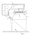
- FIG. 1 a luminaire for illuminating a merchandise display surface according to the present invention is shown.
- To the light include a lighting unit 1, which is directed to a to be illuminated effective area N - here a merchandise display area - one on the effective area N directed sensor system 2, which detects a light spectrum reflected from the useful surface N and / or objects lying on the useful surface N, and a control unit 3 with a controller board 3a and a microprocessor 3b and a power supply 3c, to which the lighting unit 1 and the Sensor 2 are connected.
- the control unit 3 is designed to control the lighting unit 1 taking into account the reflected light spectrum detected by the sensor system 2.
- the lighting unit 1 comprises a light mixing chamber 4, in which five LED modules 5 with a plurality of light in the primary colors red, green and blue of an RGB color space emitting light-emitting diodes are provided. In addition to the differently colored LEDs, each LED module 5 has a white light LED. At the bottom of the light mixing chamber, a light exit opening 6 is provided, in which a lens 7 is mounted. The inner surfaces of the light mixing chamber 4 are provided with a silver layer with a reflection-enhancing interference layer. Furthermore, a sensor system 8 connected to the control unit 3 is accommodated within the light mixing chamber 4 and detects the light spectrum of the light emitted by the LED modules 5 and mixed in the light mixing chamber 4.
- the reflector 9 is formed by two pairs of opposing side wall reflectors and end wall reflectors defining a light exit opening on its underside.
- the side wall reflectors and the end wall reflectors are formed by discrete reflector segments which are adjacent to each other in the circumferential direction and are interconnected at their upper and lower end portions.
- connecting elements in the form of hooks, not shown, are provided on the reflector segments, which are brought into engagement with each other.
- the reflector segments are made of aluminum sheet, and the inner surfaces have a vapor coating of a stainless metal for reflection enhancement.
- the sensor system 2 directed onto the illuminated useful surface N has a color sensor 10 for detecting the light spectrum reflected from the useful surface N and the objects lying thereon.
- control unit 3 At least a standard light spectrum of predetermined color temperature and / or intensity is stored.
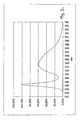
- this standard light spectrum is a white-light spectrum W, which is shown in FIG FIG. 3 is shown as a solid line.
- the control unit 3 is designed to determine a dominant color in a light spectrum detected by the sensor system 2, ie reflected by the useful surface N and the products lying thereon, and to drive the light emitting diodes of the LED modules 5 in such a way that the at least one dominant color is emphasized ,
- the stored standard light spectrum is modified in such a way that the proportion of the dominant color is enhanced and, if appropriate, the proportion of the color complementary to the at least one dominant color is additionally reduced.
- the activation of the LED modules 5 takes place in a known manner in that the power supply to the individual LEDs in the power supply 3c is changed.
- the white light spectrum W is emitted as a standard spectrum by the white light LEDs, which is superimposed by the light spectra, which are emitted by the colored light emitting diodes, and thus modified.
- two modified standard light spectra are already stored in the control unit 3, namely a first modified standard light spectrum R in which the white light spectrum is stored as a standard light spectrum with an increased red light component, and in the second modified standard light spectrum the yellow light component G is increased.
- the first modified standard light spectrum which is shown with a dashed line R
- the orange / red spectral range 600 to about 660 nm wavelength
- the blue spectral range (434 to 495 nm wavelength)
- the green / yellow wavelength range (495 to 566 nm) amplified.
- the red and the blue spectral range are just as greatly increased as in the first modified standard light spectrum R
- the green / yellow spectral range is even more increased than in the first modified standard light spectrum R.
- the maximum intensity lies in the red spectral range and is therefore in the FIG. 3 standardized with 100% indicated.
- the intensity peak in the green / yellow wavelength range is about 17% and the intensity peak in the blue wavelength range is about 22%.
- the intensity peak is more pronounced at 40%.
- the control unit 3 can be switched to a detection mode in which the lighting unit 1 and the sensor system 2 are controlled such that the lighting unit 1 emits a predetermined detection light spectrum.
- the sensor system 2 detects the light spectrum reflected by the useful surface W and / or the products lying on the useful surface N in order to determine a dominant body color.
- the detection mode is automatically activated when the lamp is put into operation.
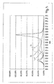
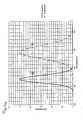
- the illumination unit sequentially emits a green light spectrum and a blue light spectrum (see FIG. 4a ), by successively irradiating the goods display area only with the green LED and then with the blue LED, and detected via the sensor 2, the respective reflected light spectra BS, GS. Subsequently, the two are reflected Light spectra BS, GS compared with each other, wherein only the light component in the wavelength range of 450 nm of the reflected blue light spectrum BS and the light component in the wavelength range of 530 nm of the reflected green light spectrum GS are considered.
- the light component in the wavelength range of 450 nm is greater than the light component in the wavelength range of 530 nm, as shown in the representation of FIG. 4b is shown, is closed on red as the dominant color and thus a meat product. If, however, the light component in the wavelength range of 450 nm is smaller than in the wavelength range of 530 nm, as in the Figure 4c is shown, is closed on yellow as the dominant color and thus baked goods.
- a goods display area with meat and meat products lying thereon should be illuminated with the above-described lamp.
- the control unit 3 switches to the detection mode, in which the illumination unit 1 displays the full intensity white light spectrum stored as the standard light spectrum ( FIG. 2 ) radiates.
- the sensor system 2 detects the light spectrum reflected by the meat and meat products, which is evaluated in the control unit 3 in order to determine the dominant color in the reflected light spectrum. This is the color red in the meat and meat products to be illuminated.
- the control unit 3 activates the lighting unit 1 to control the first modified standard light spectrum stored in the control unit 3, ie the white-light spectrum with an increased proportion of red light according to the dashed line R in FIG FIG. 3 to emit.
- the light emitted by the LEDs of the LED modules 5 light is mixed in the light mixing chamber 4, before it is irradiated through the lens 7 in the reflector 9.
- the sensors 8 provided in the light mixing chamber 4 detect the light spectrum of the light mixed in the light mixing chamber 4.
- the detected light spectrum is forwarded digitally to the control unit 3, which performs a permanent set-actual comparison of the detected light spectrum with the first modified light spectrum to be emitted. If aging or heat-related deviations are present, the control unit 3 makes corresponding adjustments in the control of the LED modules 5 until deviations no longer exist or the deviations lie within a predetermined tolerance range.
Landscapes
- Led Device Packages (AREA)
- Circuit Arrangement For Electric Light Sources In General (AREA)
Applications Claiming Priority (1)
| Application Number | Priority Date | Filing Date | Title |
|---|---|---|---|
| DE202012100632U DE202012100632U1 (de) | 2012-02-24 | 2012-02-24 | Intelligente LED |
Publications (3)
| Publication Number | Publication Date |
|---|---|
| EP2632231A2 true EP2632231A2 (fr) | 2013-08-28 |
| EP2632231A3 EP2632231A3 (fr) | 2015-07-22 |
| EP2632231B1 EP2632231B1 (fr) | 2016-02-17 |
Family
ID=45999428
Family Applications (1)
| Application Number | Title | Priority Date | Filing Date |
|---|---|---|---|
| EP13155852.0A Active EP2632231B1 (fr) | 2012-02-24 | 2013-02-19 | DEL intelligente |
Country Status (2)
| Country | Link |
|---|---|
| EP (1) | EP2632231B1 (fr) |
| DE (1) | DE202012100632U1 (fr) |
Cited By (1)
| Publication number | Priority date | Publication date | Assignee | Title |
|---|---|---|---|---|
| CN106165537A (zh) * | 2014-02-27 | 2016-11-23 | 飞利浦灯具控股公司 | 照明系统、控制器和照明方法 |
Families Citing this family (1)
| Publication number | Priority date | Publication date | Assignee | Title |
|---|---|---|---|---|
| DE102017123720A1 (de) * | 2017-10-12 | 2019-04-18 | HELLA GmbH & Co. KGaA | Kommunikationssystem für ein Kraftfahrzeug |
Family Cites Families (5)
| Publication number | Priority date | Publication date | Assignee | Title |
|---|---|---|---|---|
| DE102007004834A1 (de) | 2007-01-31 | 2008-08-14 | Airbus Deutschland Gmbh | Lichtgerät und Verfahren zur Realisierung einer gewünschten Farbmischung |
| JP2008264430A (ja) * | 2007-04-25 | 2008-11-06 | Matsushita Electric Works Ltd | 対象色強調システム |
| DE202008005509U1 (de) | 2008-02-26 | 2009-07-09 | Ledon Lighting Jennersdorf Gmbh | LED-Modul mit anwendungsspezifischer Farbeinstellung |
| DE102008055949B4 (de) | 2008-11-05 | 2010-12-23 | Siemens Aktiengesellschaft | Optische Erfassungseinheit für Objekte |
| US9125504B2 (en) * | 2010-01-28 | 2015-09-08 | Koninklijke Philips N.V. | Method and system for emphasizing object color |
-
2012
- 2012-02-24 DE DE202012100632U patent/DE202012100632U1/de not_active Expired - Lifetime
-
2013
- 2013-02-19 EP EP13155852.0A patent/EP2632231B1/fr active Active
Cited By (1)
| Publication number | Priority date | Publication date | Assignee | Title |
|---|---|---|---|---|
| CN106165537A (zh) * | 2014-02-27 | 2016-11-23 | 飞利浦灯具控股公司 | 照明系统、控制器和照明方法 |
Also Published As
| Publication number | Publication date |
|---|---|
| EP2632231B1 (fr) | 2016-02-17 |
| EP2632231A3 (fr) | 2015-07-22 |
| DE202012100632U1 (de) | 2012-03-22 |
Similar Documents
| Publication | Publication Date | Title |
|---|---|---|
| EP2541362B1 (fr) | DEL intelligente | |
| EP1956289B1 (fr) | Luminaire | |
| DE102005059362A1 (de) | Farblich einstellbare Tageslichtquelle | |
| EP1353118A3 (fr) | Projecteur changeur de couleur | |
| EP1891368A1 (fr) | Dispositif d'eclairage comprenant une source de lumiere principale et une source de lumiere supplementaire | |
| EP1951004A2 (fr) | Système de commande d'éclairage | |
| WO2015004127A1 (fr) | Lampe à led à lumière blanche | |
| DE102010039308A1 (de) | Beleuchtungsanordnung mit verschiedenfarbigen Lichtquellen sowie Verfahren zum Betreiben einer derartigen Beleuchtungsanordnung | |
| DE102016101103A1 (de) | Leuchtende Prismatische Plakette für ein Fahrzeug | |
| EP1557604B1 (fr) | Système d'éclairage | |
| EP2632231B1 (fr) | DEL intelligente | |
| AT14748U1 (de) | Leuchte | |
| DE3930214A1 (de) | Signalleuchtenpaar | |
| CH700022B1 (de) | Stehleuchte. | |
| EP2250433B1 (fr) | Lampe, en particulier à éclairage dirigé vers le bas | |
| DE102008064397A1 (de) | LED-Anordnung mit Lichtsensor | |
| WO2014161664A1 (fr) | Module à del, système d'éclairage comprenant un module à del de ce type et procédé servant à influencer un spectre lumineux | |
| DE102012009581A1 (de) | Verfahren und Vorrichtung zur Beleuchtung von Räumen | |
| EP1906077A1 (fr) | Luminaire | |
| WO2017081313A1 (fr) | Dispositif d'éclairage à del et procédé permettant d'agir sur la répartition sectrale des dispositifs d'éclairage à del | |
| EP1467141A2 (fr) | Luminaire à surface luminescente fermée | |
| DE202009011690U1 (de) | Beleuchtungskörper mit erweiterter Dimmfunktion | |
| DE102010003653B4 (de) | Verfahren zum Herstellen einer Lichtmischbox, bei dem eine Zahl der Leuchtdioden statistisch bestimmt wird, entsprechende Leuchtvorrichtung und Satz von Leuchtvorrichtungen | |
| EP2165114B1 (fr) | Lampe | |
| EP2757312B1 (fr) | Système d'éclairage pour intérieur |
Legal Events
| Date | Code | Title | Description |
|---|---|---|---|
| PUAI | Public reference made under article 153(3) epc to a published international application that has entered the european phase |
Free format text: ORIGINAL CODE: 0009012 |
|
| AK | Designated contracting states |
Kind code of ref document: A2 Designated state(s): AL AT BE BG CH CY CZ DE DK EE ES FI FR GB GR HR HU IE IS IT LI LT LU LV MC MK MT NL NO PL PT RO RS SE SI SK SM TR |
|
| AX | Request for extension of the european patent |
Extension state: BA ME |
|
| PUAL | Search report despatched |
Free format text: ORIGINAL CODE: 0009013 |
|
| AK | Designated contracting states |
Kind code of ref document: A3 Designated state(s): AL AT BE BG CH CY CZ DE DK EE ES FI FR GB GR HR HU IE IS IT LI LT LU LV MC MK MT NL NO PL PT RO RS SE SI SK SM TR |
|
| AX | Request for extension of the european patent |
Extension state: BA ME |
|
| RIC1 | Information provided on ipc code assigned before grant |
Ipc: G05D 25/02 20060101ALI20150617BHEP Ipc: H05B 33/08 20060101AFI20150617BHEP |
|
| 17P | Request for examination filed |
Effective date: 20150817 |
|
| GRAP | Despatch of communication of intention to grant a patent |
Free format text: ORIGINAL CODE: EPIDOSNIGR1 |
|
| RBV | Designated contracting states (corrected) |
Designated state(s): AL AT BE BG CH CY CZ DE DK EE ES FI FR GB GR HR HU IE IS IT LI LT LU LV MC MK MT NL NO PL PT RO RS SE SI SK SM TR |
|
| INTG | Intention to grant announced |
Effective date: 20151001 |
|
| GRAS | Grant fee paid |
Free format text: ORIGINAL CODE: EPIDOSNIGR3 |
|
| GRAA | (expected) grant |
Free format text: ORIGINAL CODE: 0009210 |
|
| REG | Reference to a national code |
Ref country code: FR Ref legal event code: PLFP Year of fee payment: 4 |
|
| AK | Designated contracting states |
Kind code of ref document: B1 Designated state(s): AL AT BE BG CH CY CZ DE DK EE ES FI FR GB GR HR HU IE IS IT LI LT LU LV MC MK MT NL NO PL PT RO RS SE SI SK SM TR |
|
| REG | Reference to a national code |
Ref country code: GB Ref legal event code: FG4D Free format text: NOT ENGLISH |
|
| REG | Reference to a national code |
Ref country code: CH Ref legal event code: EP |
|
| REG | Reference to a national code |
Ref country code: IE Ref legal event code: FG4D Free format text: LANGUAGE OF EP DOCUMENT: GERMAN |
|
| REG | Reference to a national code |
Ref country code: AT Ref legal event code: REF Ref document number: 776144 Country of ref document: AT Kind code of ref document: T Effective date: 20160315 |
|
| REG | Reference to a national code |
Ref country code: DE Ref legal event code: R096 Ref document number: 502013001948 Country of ref document: DE |
|
| REG | Reference to a national code |
Ref country code: NL Ref legal event code: MP Effective date: 20160217 |
|
| REG | Reference to a national code |
Ref country code: LT Ref legal event code: MG4D |
|
| PG25 | Lapsed in a contracting state [announced via postgrant information from national office to epo] |
Ref country code: ES Free format text: LAPSE BECAUSE OF FAILURE TO SUBMIT A TRANSLATION OF THE DESCRIPTION OR TO PAY THE FEE WITHIN THE PRESCRIBED TIME-LIMIT Effective date: 20160217 Ref country code: HR Free format text: LAPSE BECAUSE OF FAILURE TO SUBMIT A TRANSLATION OF THE DESCRIPTION OR TO PAY THE FEE WITHIN THE PRESCRIBED TIME-LIMIT Effective date: 20160217 Ref country code: IT Free format text: LAPSE BECAUSE OF FAILURE TO SUBMIT A TRANSLATION OF THE DESCRIPTION OR TO PAY THE FEE WITHIN THE PRESCRIBED TIME-LIMIT Effective date: 20160217 Ref country code: GR Free format text: LAPSE BECAUSE OF FAILURE TO SUBMIT A TRANSLATION OF THE DESCRIPTION OR TO PAY THE FEE WITHIN THE PRESCRIBED TIME-LIMIT Effective date: 20160518 Ref country code: FI Free format text: LAPSE BECAUSE OF FAILURE TO SUBMIT A TRANSLATION OF THE DESCRIPTION OR TO PAY THE FEE WITHIN THE PRESCRIBED TIME-LIMIT Effective date: 20160217 Ref country code: NO Free format text: LAPSE BECAUSE OF FAILURE TO SUBMIT A TRANSLATION OF THE DESCRIPTION OR TO PAY THE FEE WITHIN THE PRESCRIBED TIME-LIMIT Effective date: 20160517 |
|
| PG25 | Lapsed in a contracting state [announced via postgrant information from national office to epo] |
Ref country code: NL Free format text: LAPSE BECAUSE OF FAILURE TO SUBMIT A TRANSLATION OF THE DESCRIPTION OR TO PAY THE FEE WITHIN THE PRESCRIBED TIME-LIMIT Effective date: 20160217 Ref country code: LV Free format text: LAPSE BECAUSE OF FAILURE TO SUBMIT A TRANSLATION OF THE DESCRIPTION OR TO PAY THE FEE WITHIN THE PRESCRIBED TIME-LIMIT Effective date: 20160217 Ref country code: BE Free format text: LAPSE BECAUSE OF NON-PAYMENT OF DUE FEES Effective date: 20160229 Ref country code: LT Free format text: LAPSE BECAUSE OF FAILURE TO SUBMIT A TRANSLATION OF THE DESCRIPTION OR TO PAY THE FEE WITHIN THE PRESCRIBED TIME-LIMIT Effective date: 20160217 Ref country code: RS Free format text: LAPSE BECAUSE OF FAILURE TO SUBMIT A TRANSLATION OF THE DESCRIPTION OR TO PAY THE FEE WITHIN THE PRESCRIBED TIME-LIMIT Effective date: 20160217 Ref country code: SE Free format text: LAPSE BECAUSE OF FAILURE TO SUBMIT A TRANSLATION OF THE DESCRIPTION OR TO PAY THE FEE WITHIN THE PRESCRIBED TIME-LIMIT Effective date: 20160217 Ref country code: PL Free format text: LAPSE BECAUSE OF FAILURE TO SUBMIT A TRANSLATION OF THE DESCRIPTION OR TO PAY THE FEE WITHIN THE PRESCRIBED TIME-LIMIT Effective date: 20160217 Ref country code: PT Free format text: LAPSE BECAUSE OF FAILURE TO SUBMIT A TRANSLATION OF THE DESCRIPTION OR TO PAY THE FEE WITHIN THE PRESCRIBED TIME-LIMIT Effective date: 20160617 |
|
| REG | Reference to a national code |
Ref country code: CH Ref legal event code: PL |
|
| PG25 | Lapsed in a contracting state [announced via postgrant information from national office to epo] |
Ref country code: DK Free format text: LAPSE BECAUSE OF FAILURE TO SUBMIT A TRANSLATION OF THE DESCRIPTION OR TO PAY THE FEE WITHIN THE PRESCRIBED TIME-LIMIT Effective date: 20160217 Ref country code: CH Free format text: LAPSE BECAUSE OF NON-PAYMENT OF DUE FEES Effective date: 20160229 Ref country code: EE Free format text: LAPSE BECAUSE OF FAILURE TO SUBMIT A TRANSLATION OF THE DESCRIPTION OR TO PAY THE FEE WITHIN THE PRESCRIBED TIME-LIMIT Effective date: 20160217 Ref country code: LI Free format text: LAPSE BECAUSE OF NON-PAYMENT OF DUE FEES Effective date: 20160229 |
|
| REG | Reference to a national code |
Ref country code: DE Ref legal event code: R097 Ref document number: 502013001948 Country of ref document: DE |
|
| PG25 | Lapsed in a contracting state [announced via postgrant information from national office to epo] |
Ref country code: SM Free format text: LAPSE BECAUSE OF FAILURE TO SUBMIT A TRANSLATION OF THE DESCRIPTION OR TO PAY THE FEE WITHIN THE PRESCRIBED TIME-LIMIT Effective date: 20160217 Ref country code: RO Free format text: LAPSE BECAUSE OF FAILURE TO SUBMIT A TRANSLATION OF THE DESCRIPTION OR TO PAY THE FEE WITHIN THE PRESCRIBED TIME-LIMIT Effective date: 20160217 Ref country code: SK Free format text: LAPSE BECAUSE OF FAILURE TO SUBMIT A TRANSLATION OF THE DESCRIPTION OR TO PAY THE FEE WITHIN THE PRESCRIBED TIME-LIMIT Effective date: 20160217 Ref country code: CZ Free format text: LAPSE BECAUSE OF FAILURE TO SUBMIT A TRANSLATION OF THE DESCRIPTION OR TO PAY THE FEE WITHIN THE PRESCRIBED TIME-LIMIT Effective date: 20160217 |
|
| REG | Reference to a national code |
Ref country code: IE Ref legal event code: MM4A |
|
| PLBE | No opposition filed within time limit |
Free format text: ORIGINAL CODE: 0009261 |
|
| STAA | Information on the status of an ep patent application or granted ep patent |
Free format text: STATUS: NO OPPOSITION FILED WITHIN TIME LIMIT |
|
| REG | Reference to a national code |
Ref country code: FR Ref legal event code: PLFP Year of fee payment: 5 |
|
| 26N | No opposition filed |
Effective date: 20161118 |
|
| PG25 | Lapsed in a contracting state [announced via postgrant information from national office to epo] |
Ref country code: IE Free format text: LAPSE BECAUSE OF NON-PAYMENT OF DUE FEES Effective date: 20160219 |
|
| PG25 | Lapsed in a contracting state [announced via postgrant information from national office to epo] |
Ref country code: SI Free format text: LAPSE BECAUSE OF FAILURE TO SUBMIT A TRANSLATION OF THE DESCRIPTION OR TO PAY THE FEE WITHIN THE PRESCRIBED TIME-LIMIT Effective date: 20160217 Ref country code: BG Free format text: LAPSE BECAUSE OF FAILURE TO SUBMIT A TRANSLATION OF THE DESCRIPTION OR TO PAY THE FEE WITHIN THE PRESCRIBED TIME-LIMIT Effective date: 20160517 |
|
| PG25 | Lapsed in a contracting state [announced via postgrant information from national office to epo] |
Ref country code: MT Free format text: LAPSE BECAUSE OF FAILURE TO SUBMIT A TRANSLATION OF THE DESCRIPTION OR TO PAY THE FEE WITHIN THE PRESCRIBED TIME-LIMIT Effective date: 20160217 |
|
| REG | Reference to a national code |
Ref country code: FR Ref legal event code: PLFP Year of fee payment: 6 |
|
| PG25 | Lapsed in a contracting state [announced via postgrant information from national office to epo] |
Ref country code: CY Free format text: LAPSE BECAUSE OF FAILURE TO SUBMIT A TRANSLATION OF THE DESCRIPTION OR TO PAY THE FEE WITHIN THE PRESCRIBED TIME-LIMIT Effective date: 20160217 Ref country code: HU Free format text: LAPSE BECAUSE OF FAILURE TO SUBMIT A TRANSLATION OF THE DESCRIPTION OR TO PAY THE FEE WITHIN THE PRESCRIBED TIME-LIMIT; INVALID AB INITIO Effective date: 20130219 |
|
| PG25 | Lapsed in a contracting state [announced via postgrant information from national office to epo] |
Ref country code: LU Free format text: LAPSE BECAUSE OF NON-PAYMENT OF DUE FEES Effective date: 20160219 Ref country code: TR Free format text: LAPSE BECAUSE OF FAILURE TO SUBMIT A TRANSLATION OF THE DESCRIPTION OR TO PAY THE FEE WITHIN THE PRESCRIBED TIME-LIMIT Effective date: 20160217 Ref country code: MC Free format text: LAPSE BECAUSE OF FAILURE TO SUBMIT A TRANSLATION OF THE DESCRIPTION OR TO PAY THE FEE WITHIN THE PRESCRIBED TIME-LIMIT Effective date: 20160217 Ref country code: IS Free format text: LAPSE BECAUSE OF FAILURE TO SUBMIT A TRANSLATION OF THE DESCRIPTION OR TO PAY THE FEE WITHIN THE PRESCRIBED TIME-LIMIT Effective date: 20160217 Ref country code: MK Free format text: LAPSE BECAUSE OF FAILURE TO SUBMIT A TRANSLATION OF THE DESCRIPTION OR TO PAY THE FEE WITHIN THE PRESCRIBED TIME-LIMIT Effective date: 20160217 |
|
| PG25 | Lapsed in a contracting state [announced via postgrant information from national office to epo] |
Ref country code: AL Free format text: LAPSE BECAUSE OF FAILURE TO SUBMIT A TRANSLATION OF THE DESCRIPTION OR TO PAY THE FEE WITHIN THE PRESCRIBED TIME-LIMIT Effective date: 20160217 |
|
| REG | Reference to a national code |
Ref country code: AT Ref legal event code: MM01 Ref document number: 776144 Country of ref document: AT Kind code of ref document: T Effective date: 20180219 |
|
| PG25 | Lapsed in a contracting state [announced via postgrant information from national office to epo] |
Ref country code: AT Free format text: LAPSE BECAUSE OF NON-PAYMENT OF DUE FEES Effective date: 20180219 |
|
| REG | Reference to a national code |
Ref country code: DE Ref legal event code: R079 Ref document number: 502013001948 Country of ref document: DE Free format text: PREVIOUS MAIN CLASS: H05B0033080000 Ipc: H05B0045000000 |
|
| PGFP | Annual fee paid to national office [announced via postgrant information from national office to epo] |
Ref country code: GB Payment date: 20200225 Year of fee payment: 8 |
|
| GBPC | Gb: european patent ceased through non-payment of renewal fee |
Effective date: 20210219 |
|
| PG25 | Lapsed in a contracting state [announced via postgrant information from national office to epo] |
Ref country code: GB Free format text: LAPSE BECAUSE OF NON-PAYMENT OF DUE FEES Effective date: 20210219 |
|
| PGFP | Annual fee paid to national office [announced via postgrant information from national office to epo] |
Ref country code: FR Payment date: 20230207 Year of fee payment: 11 |
|
| PG25 | Lapsed in a contracting state [announced via postgrant information from national office to epo] |
Ref country code: FR Free format text: LAPSE BECAUSE OF NON-PAYMENT OF DUE FEES Effective date: 20240229 |
|
| PG25 | Lapsed in a contracting state [announced via postgrant information from national office to epo] |
Ref country code: FR Free format text: LAPSE BECAUSE OF NON-PAYMENT OF DUE FEES Effective date: 20240229 |
|
| PGFP | Annual fee paid to national office [announced via postgrant information from national office to epo] |
Ref country code: DE Payment date: 20250220 Year of fee payment: 13 |