EP2632603B1 - Dispositif pour pulvériser un liquide sous pression - Google Patents
Dispositif pour pulvériser un liquide sous pression Download PDFInfo
- Publication number
- EP2632603B1 EP2632603B1 EP11764459.1A EP11764459A EP2632603B1 EP 2632603 B1 EP2632603 B1 EP 2632603B1 EP 11764459 A EP11764459 A EP 11764459A EP 2632603 B1 EP2632603 B1 EP 2632603B1
- Authority
- EP
- European Patent Office
- Prior art keywords
- swirl
- chamber
- axis
- longitudinal
- chambers
- Prior art date
- Legal status (The legal status is an assumption and is not a legal conclusion. Google has not performed a legal analysis and makes no representation as to the accuracy of the status listed.)
- Active
Links
Images



Classifications
-
- B—PERFORMING OPERATIONS; TRANSPORTING
- B05—SPRAYING OR ATOMISING IN GENERAL; APPLYING FLUENT MATERIALS TO SURFACES, IN GENERAL
- B05B—SPRAYING APPARATUS; ATOMISING APPARATUS; NOZZLES
- B05B1/00—Nozzles, spray heads or other outlets, with or without auxiliary devices such as valves, heating means
- B05B1/34—Nozzles, spray heads or other outlets, with or without auxiliary devices such as valves, heating means designed to influence the nature of flow of the liquid or other fluent material, e.g. to produce swirl
- B05B1/3405—Nozzles, spray heads or other outlets, with or without auxiliary devices such as valves, heating means designed to influence the nature of flow of the liquid or other fluent material, e.g. to produce swirl to produce swirl
- B05B1/341—Nozzles, spray heads or other outlets, with or without auxiliary devices such as valves, heating means designed to influence the nature of flow of the liquid or other fluent material, e.g. to produce swirl to produce swirl before discharging the liquid or other fluent material, e.g. in a swirl chamber upstream the spray outlet
-
- B—PERFORMING OPERATIONS; TRANSPORTING
- B05—SPRAYING OR ATOMISING IN GENERAL; APPLYING FLUENT MATERIALS TO SURFACES, IN GENERAL
- B05B—SPRAYING APPARATUS; ATOMISING APPARATUS; NOZZLES
- B05B1/00—Nozzles, spray heads or other outlets, with or without auxiliary devices such as valves, heating means
- B05B1/26—Nozzles, spray heads or other outlets, with or without auxiliary devices such as valves, heating means with means for mechanically breaking-up or deflecting the jet after discharge, e.g. with fixed deflectors; Breaking-up the discharged liquid or other fluent material by impinging jets
-
- B—PERFORMING OPERATIONS; TRANSPORTING
- B05—SPRAYING OR ATOMISING IN GENERAL; APPLYING FLUENT MATERIALS TO SURFACES, IN GENERAL
- B05B—SPRAYING APPARATUS; ATOMISING APPARATUS; NOZZLES
- B05B1/00—Nozzles, spray heads or other outlets, with or without auxiliary devices such as valves, heating means
- B05B1/34—Nozzles, spray heads or other outlets, with or without auxiliary devices such as valves, heating means designed to influence the nature of flow of the liquid or other fluent material, e.g. to produce swirl
- B05B1/3405—Nozzles, spray heads or other outlets, with or without auxiliary devices such as valves, heating means designed to influence the nature of flow of the liquid or other fluent material, e.g. to produce swirl to produce swirl
- B05B1/341—Nozzles, spray heads or other outlets, with or without auxiliary devices such as valves, heating means designed to influence the nature of flow of the liquid or other fluent material, e.g. to produce swirl to produce swirl before discharging the liquid or other fluent material, e.g. in a swirl chamber upstream the spray outlet
- B05B1/3421—Nozzles, spray heads or other outlets, with or without auxiliary devices such as valves, heating means designed to influence the nature of flow of the liquid or other fluent material, e.g. to produce swirl to produce swirl before discharging the liquid or other fluent material, e.g. in a swirl chamber upstream the spray outlet with channels emerging substantially tangentially in the swirl chamber
- B05B1/3431—Nozzles, spray heads or other outlets, with or without auxiliary devices such as valves, heating means designed to influence the nature of flow of the liquid or other fluent material, e.g. to produce swirl to produce swirl before discharging the liquid or other fluent material, e.g. in a swirl chamber upstream the spray outlet with channels emerging substantially tangentially in the swirl chamber the channels being formed at the interface of cooperating elements, e.g. by means of grooves
-
- B—PERFORMING OPERATIONS; TRANSPORTING
- B05—SPRAYING OR ATOMISING IN GENERAL; APPLYING FLUENT MATERIALS TO SURFACES, IN GENERAL
- B05B—SPRAYING APPARATUS; ATOMISING APPARATUS; NOZZLES
- B05B15/00—Details of spraying plant or spraying apparatus not otherwise provided for; Accessories
- B05B15/40—Filters located upstream of the spraying outlets
-
- E—FIXED CONSTRUCTIONS
- E03—WATER SUPPLY; SEWERAGE
- E03C—DOMESTIC PLUMBING INSTALLATIONS FOR FRESH WATER OR WASTE WATER; SINKS
- E03C1/00—Domestic plumbing installations for fresh water or waste water; Sinks
- E03C1/02—Plumbing installations for fresh water
- E03C1/08—Jet regulators or jet guides, e.g. anti-splash devices
-
- B—PERFORMING OPERATIONS; TRANSPORTING
- B05—SPRAYING OR ATOMISING IN GENERAL; APPLYING FLUENT MATERIALS TO SURFACES, IN GENERAL
- B05B—SPRAYING APPARATUS; ATOMISING APPARATUS; NOZZLES
- B05B1/00—Nozzles, spray heads or other outlets, with or without auxiliary devices such as valves, heating means
- B05B1/14—Nozzles, spray heads or other outlets, with or without auxiliary devices such as valves, heating means with multiple outlet openings; with strainers in or outside the outlet opening
- B05B1/18—Roses; Shower heads
-
- Y—GENERAL TAGGING OF NEW TECHNOLOGICAL DEVELOPMENTS; GENERAL TAGGING OF CROSS-SECTIONAL TECHNOLOGIES SPANNING OVER SEVERAL SECTIONS OF THE IPC; TECHNICAL SUBJECTS COVERED BY FORMER USPC CROSS-REFERENCE ART COLLECTIONS [XRACs] AND DIGESTS
- Y10—TECHNICAL SUBJECTS COVERED BY FORMER USPC
- Y10S—TECHNICAL SUBJECTS COVERED BY FORMER USPC CROSS-REFERENCE ART COLLECTIONS [XRACs] AND DIGESTS
- Y10S239/00—Fluid sprinkling, spraying, and diffusing
- Y10S239/17—Low volume
Definitions
- the present invention relates to a device for spraying a pressurized liquid, in particular water, with which a very good cleaning effect can be achieved despite a very low flow rate.
- a device for spraying a pressurized liquid, in particular water, with which a very good cleaning effect can be achieved despite a very low flow rate.
- Such a device can be designed in particular as a mouthpiece for sanitary outlet fittings or as an insert for a shower head or the like.
- Such a vortex chamber is eg in RU 2 196 205 disclosed.
- the vortex chamber shown there has a conical shape.
- the water is supplied to the vortex chamber in the region of the largest cross section of the cone through a tangential inlet channel and leaves the vortex chamber through an axial outlet channel.
- a whirl chamber is also in WO 2008/073062 disclosed.
- This document discloses a mouthpiece for a sanitary outlet fitting, which is switchable between a economy mode and a normal mode.
- economy mode the incoming water is introduced tangentially through two channels from opposite sides into a short, cylindrical vortex chamber from which it exits axially through a central outlet opening.
- normal mode the water passes bypassing the vortex chamber to the central outlet opening and also to several other, decentralized outlet openings, so that a much larger volume flow is achieved.
- a spray head for spraying highly viscous liquids which in one embodiment has vortex chambers.
- the liquid jets emerging from the vortex chambers then meet one another.
- EP 1 277 516 and WO 93/23174 each disclose a spray head with two nozzles, the vortex channels and are directed towards each other, that meet the resulting rays.
- the device should be simple and inexpensive to produce in large quantities. This object is achieved by a device having the features of claim 1. Further embodiments are given in the dependent claims.
- each of the outlet nozzles defines a nozzle longitudinal axis (in the case of an at least sectionally cylindrical outlet nozzle, the nozzle longitudinal axis is identical to the cylinder axis).
- the nozzle longitudinal axes are inclined relative to each other such that liquid jets emerging from the outlet nozzles meet at a predetermined distance from the outlet nozzles. This is achieved by that the nozzle longitudinal axes outside the device substantially intersect at an intersection having the mentioned distance from the outlet nozzles.
- a device which produces a significantly improved cleaning effect at the same time low volume flow compared to a single vortex chamber. If e.g. three swirl chambers are used, it is possible to achieve an excellent cleaning action for washing hands at a normal line pressure of about 3 bar and a total flow of only 0.6 l / min. Since the liquid jets leave the outlet nozzles in finely divided form thanks to the vortex chambers, it is completely unproblematic if these rays impinge on the skin of a user before the rays meet with each other.
- the device can be used in a variety of ways.
- the device may e.g. as a mouthpiece for a sanitary outlet fitting for cold or hot tap water, e.g. be formed on a washbasin or bidet.
- the device may e.g. also as a spray head of a shower toilet, as a normal shower head shower head, as a replaceable use of such a shower head, as a spray head in a spa, etc. are used.
- use is e.g. in the camping area possible, for example in a motor home or caravan, or on vanities or even showers in aircraft.
- the liquid to be sprayed does not necessarily have to be water, but may e.g. also be a detergent solution provided with detergents.
- the invention can be used to advantage in all applications in which a good cleaning performance is desired at a low flow rate.
- the device has at least three vortex chambers with associated outlet nozzles whose liquid jets meet.
- a reasonable upper limit for the number of vortex chambers seems to be around ten.
- the vortex chambers and outlet nozzles are preferably arranged annularly around a central device longitudinal axis. In this case, the outlet nozzles are preferably distributed uniformly along the circumferential direction of the ring. However, other arrangements can be selected.
- the axial distance from the outlet nozzles, at which the liquid jets meet, is preferably between 40 mm and 150 mm, but may also take on larger values depending on the application. For use in sanitary outlet fittings, a distance of about 80 mm is preferred. For typical dimensions of mouthpieces for sanitary outlet fittings and an annular arrangement of the outlet nozzles, this distance corresponds to an angle of inclination of the nozzle longitudinal axes relative to the central device longitudinal axis of about 3 °. Depending on the dimensions of the device and the intended application, however, this angle of inclination may also be greater or smaller and is 1 ° -10 °, preferably about 2 ° -5 °
- a vortex chamber is understood to mean a chamber which, by virtue of its geometry, causes a vortex about a vortex axis due to its geometry (ie generates a vortex around the vortex axis) and which has an outlet nozzle such that the water is substantially axial exits to the vortex axis.
- the vortex chamber is preferably designed as follows.
- the vortex chamber defines a chamber longitudinal axis.
- the inlet of the vortex chamber is formed in an inlet region of the vortex chamber such that the supply of the liquid into the vortex chamber takes place essentially tangentially with respect to the chamber longitudinal axis.
- the outlet nozzle is arranged essentially centrally with respect to the longitudinal axis of the chamber.
- the nozzle longitudinal axis and the chamber longitudinal axis extend either coaxially or include an angle of at most 15 ° to each other, preferably at most 10 °, more preferably at most 5 °.
- the chamber longitudinal axes of the vortex chambers are substantially parallel to each other, and in particular parallel to a common longitudinal axis device, while the nozzle longitudinal axes are inclined to the longitudinal axis of the chamber or the device longitudinal axis.
- the outlet nozzle is arranged axially spaced from the inlet region with respect to the longitudinal axis of the chamber.
- the vortex chamber preferably tapers in a funnel shape between the inlet region and the outlet nozzle.
- each of the vortex chambers preferably has a substantially conical region in which the cross section of the vortex chamber tapers continuously along the chamber longitudinal axis as far as the outlet nozzle.
- This conical area can be a substantially cylindrical Axial and upstream upstream region, which is arranged between the inlet region and the conical region.
- substantially cylindrical are also to consider shapes that differ to a small degree from a purely cylindrical shape, without significantly changing the function of this area, eg frusto-conical shapes with a small opening angle, especially when the opening angle (angle between diametrically opposite lateral surface areas ) is less than 2 x 10 ° or even less than 2 x 5 °.
- a cam in each of the vortex chambers, may be arranged, which extends centrally along the chamber longitudinal axis in the inlet region of the vortex chamber, so that the inlet region of the vortex chamber forms an annular cavity.
- the cam is preferably cylindrical in shape, but may e.g. also assume a truncated cone shape.
- the outlet nozzles are preferably formed by cylindrical bores. However, even if the outlet nozzles should have a different shape, preferably each outlet nozzle has at its end a cylindrical outlet region, which is adjoined externally by a substantially flat outlet surface which is orthogonal to the cylinder axis. In particular, the outlet nozzle preferably does not expand outwardly at its exterior end. Between the exit region and the associated exit surface, a sharp edge is preferably formed in order to facilitate the detachment of the liquid jet from the outlet nozzle. Overall, this results in a clean spray pattern.
- the vortex chambers are at least partially, but at least the outlet nozzles are formed in a common (preferably one-piece) vortex chamber element. It is preferred in terms of production engineering if, in the swirl chamber element, a flat, preferably frusto-conical recess is formed on the outside in the region of each outlet nozzle, whose conical axis coincides with the nozzle axis and which Exit surface forms.
- the apparatus has a liquid central supply channel extending along a device axis, which can optionally taper in the axial direction to achieve a first acceleration of the incoming liquid stream.
- the vortex chambers are then arranged decentralized to the device axis, e.g. annular around the device axis, and the inlet channels connect the feed channel to the vortex chambers substantially transverse to the device axis.
- An improved vortex formation can be achieved if each of the inlet channels from the feed channel describes an arc with an angle of at least 90 °.
- each of the inlet channels has a rectangular cross-section. It is preferred if the cross section is substantially constant over the length of the inlet channel.
- the cross-sectional area of the inlet channels has a significant influence on the volume flow at a given operating pressure.
- the volume flow can thus be adjusted for a given operating pressure. This eliminates the use of a separate flow restrictor.
- the device is manufactured particularly simply because it has a (preferably one-piece) supply element and a (preferably also one-piece) swirl chamber element which are interconnected (in particular rest on one another) so that together they delimit at least a portion of each inlet channel, the vortex chambers at least partially formed by depressions (eg holes) in the vortex chamber element. It is preferred that the vortex chamber element and the feed element with respect to the longitudinal axis of the device rest on the front side, ie substantially along a common plane which is perpendicular to the device longitudinal axis, rest on each other.
- the inlet channels through depressions (eg grooves) in Feed element are formed, while the swirl chamber element has a supply element facing end face, which is substantially flat in the region of the inlet channels, so as to limit the inlet channels together with the feed element.
- the device can also be adapted very easily to different pressure ranges by merely exchanging the feed element for another feed element with a different cross-sectional area of the inlet channels, while the vortex chamber element can remain unchanged independently of the pressure range.
- At least one decentralized positioning cam can be formed on the feed element or swirl chamber element, which engages in a complementary positioning groove on the other element.
- positioning can also be achieved in other ways, e.g. by the provision of laterally perforated hollow pins, which are formed on the feed element and protrude in a region surrounding the inlet region of the vortex chambers in depressions of the vortex chamber element.
- the feed element and the swirl chamber element can be jointly held in a receiving sleeve such that the feed element, the swirl chamber element and the receiving sleeve together form a replaceable unit ("service unit").
- the swirl chamber element abut against an inside axial stop of the receiving sleeve (if necessary, with a gasket disposed therebetween), while the feed element rests on the swirl chamber element and is held on the receiving sleeve, e.g. through a snap connection.
- one or more snap arms can be formed on the feed element, which engage in corresponding inner recesses of the receiving sleeve.
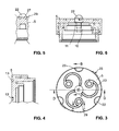
- FIGS. 3 and 6 a mouthpiece 1 a sanitary outlet fitting according to a first embodiment of the invention is shown.
- An outer sleeve 2 has a connecting thread 3, which fits in commercial washbasin taps.
- a receiving sleeve which is referred to below as the inner sleeve 4
- a feed element which is referred to below as the housing insert 5
- a swirl chamber element which is referred to below as a swirl disk 6 added.
- these parts are preferably made of a dirt and lime repellent material.
- the housing insert 5 and / or the swirl disk 6 can be manufactured by injection molding of plastic.
- the housing insert 5 is in the FIGS. 3 to 6 additionally shown in different views alone.
- a snapped in the housing insert 5 particulate filter 7 prevents the ingress of dirt or sand particles in the mouthpiece.
- a seal 8 in the form of a sealing ring with a square or rectangular cross section establishes a seal between the outlet fitting and the interior of the inner sleeve 4.
- a further seal 9 in the form of an O-ring establishes a seal between the inner sleeve 4 and the swirl disk 6.
- a central bore 10 is formed, which tapers stepwise down to a cylindrical feed channel 11.
- the bore 10 defines with its cylinder axis a central device longitudinal axis 21.
- three inlet channels 13 extend transversely to the device longitudinal axis 21 to three decentralized, circumferentially about the device longitudinal axis arranged vortex chambers 14.
- Each of the inlet channels 13 initially extends radially in a radial portion 12 substantially radially outwards and then describes an arc of something more than 180 °, before it opens tangentially into the respective vortex chamber 14.
- the inlet channels are formed as recesses with a rectangular cross section in that end face of the housing insert 5, which is opposite to the vortex disc 6.
- the opposite end face of the swirl disk 6 is flat and smooth in the region of the inlet channels 13. In this way, the housing insert 5 and the swirl disk 6 together define the inlet channels 13.
- Each of the vortex chambers 14 has an inlet region 29, into which the associated inlet channel 13 opens substantially tangentially.
- the inlet region 29 is formed in the housing insert 5 as an annular cavity with a rectangular cross-section.
- a cylindrical pin 27 is arranged, which is formed on the housing insert 5 and extends from above into the inlet region.
- the length of the pin substantially corresponds to the height of the inlet channels, so that the pin axially ends in the common plane which separates the housing insert 5 and the swirl disk 6.
- a cylindrical region 15 (transition region) in the form of a cylindrical bore in the swirl disk 6 adjoins the inlet region 29 in an axial direction, which in turn is followed by a conically tapered region 16.
- the tapered region 16 opens into a centrally disposed, axially extending, cylindrical outlet nozzle 18.
- the outlet nozzle 18 terminates at a right angle to the cylinder axis of the nozzle extending exit surface 17, wherein between the cylindrical nozzle bore and the exit surface is formed a sharp edge.
- the exit surface is formed by a flat, frusto-conical recess 19 in the outer side end face of the vertebral disc 6 and thereby has a ring shape.
- each swirl chamber 14 defines a chamber longitudinal axis 32.
- the cylinder axis of the associated outlet nozzle 18 defines a nozzle longitudinal axis 20.
- the chamber longitudinal axis 32 and the nozzle longitudinal axis 20 coincide and are tilted together by approximately 3 ° to the device longitudinal axis 21.
- the nozzle longitudinal axes 20 meet at a common point of intersection at a distance of about 80 mm from the exit surfaces of the nozzles.
- the chamber longitudinal axis and the longitudinal axis of the nozzle may alternatively assume a small angle to one another. This will be explained below in connection with the Fig. 12 explained in more detail.
- water passes axially through the particulate filter 7 (whose mesh is less than the smallest cross-sectional dimension of the inlet channels 13 and the outlet nozzles 18) into the central bore 10 and from there into the feed channel 11. Due to the tapered shape of the central bore 10 of the water flow is thereby accelerated a first time.
- the water is distributed to the inlet channels 13 and thereby deflected.
- the water is fed to the vortex chambers 14.
- the water enters tangentially into the inlet region 29 of each vortex chamber 14 and begins to describe a spiral movement there.
- the central cam 27 in the inlet region additionally supports the formation of a vortex movement.
- the resulting vortex now moves down the cylindrical portion 15 and is further accelerated in the tapered portion 16 before entering the outlet nozzle 18.
- the water leaves the outlet nozzle 18 at high speed and is thereby broken up into fine droplets.
- the sharp-edged design of the transition between the cylindrical nozzle bore and the exit surface 17 supports a clean detachment of the water jet. In this way, a finely divided, directed beam without excessive formation of non-directional spray.
- These previously divided water jets meet each other approx. 80 mm below the exit surface at the intersection of the longitudinal axis of the nozzles and ensure optimum cleaning performance in this area.
- the hands can be completely moistened for washing, and also soap or other cleaning agents can easily be rinsed off again by the hands.
- the dimensions of the mouthpiece e.g. as follows: Outer diameter of the mouthpiece approx. 24 mm; Distance of the nozzle outlets from the central longitudinal axis of the device approx. 4.2 mm; Inclination angle of the nozzle longitudinal axis and the chamber longitudinal axis to the device longitudinal axis about 3 °; Cross section of the inlet channels rectangular, approx. 1 mm wide, 0.5 mm deep; resulting volume flow at a flow pressure of 3 bar is approx. 0.2 l / min per outlet nozzle (total volume flow approx. 0.6 l / min).
- these parameters can be varied within wide ranges. In particular, can be adjusted by a suitable choice of the cross-sectional area of the inlet channels, a larger or smaller volume flow at a given flow pressure, or the mouthpiece can be adapted to different pressure conditions at a given volume flow.
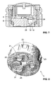
- a mouthpiece according to a second embodiment of the invention is in the FIGS. 7 and 8 illustrated.
- the structure of this mouthpiece largely corresponds to the first embodiment, and like-acting parts are provided with the same reference numerals as in the first embodiment.
- the snap arms 23 on the housing insert 5 well recognizable, which go together with the inner sleeve the already mentioned snap connection.
- This embodiment differs from the first embodiment mainly by the manner in which the housing insert 5 and the swirl disk 6 are secured relative to each other against rotation.
- each hollow pin 25 is interrupted by an opening 31.
- this embodiment also eliminates the central pin 27, which projects axially into the inlet region 29 of the vortex chamber 14 in the first embodiment.
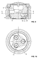
- a mouthpiece according to a third embodiment is in the FIGS. 9 and 10 illustrated. Again, like-acting parts are given the same reference numerals as in the first embodiment.
- the inlet channels 13 have a different shape than in the first two embodiments;
- the inlet channels are not formed as depressions in the housing insert 5, but as depressions in the end face of the vertebral disk 6. Instead of an arcuate shape with a constant cross section, the inlet channels here have a fan-shaped shape with a strongly tapering cross-section. As a result, an acceleration of the water flow takes place here in the inlet channels.
- a mouthpiece according to a fourth embodiment is in FIG. 11 shown. Again, like-acting parts are given the same reference numerals as in the first embodiment.
- the cross section of the inlet channels 13 is here semicircular instead of rectangular.
- a commercially available flow restrictor 28 is used in the central bore 10 .
- the mouthpiece can be adapted to higher flow pressures in a very simple manner, without changing the dimensions.
- a mouthpiece according to a fifth embodiment of the invention is in the FIG. 12 illustrated.
- the structure of this mouthpiece largely corresponds to the first embodiment, and like-acting parts are again provided with the same reference numerals as in the first embodiment.
- This embodiment differs from the first embodiment in that the chamber longitudinal axis 32 of each vortex chamber does not coincide with the nozzle longitudinal axis 20 of the respective vortex chamber. Instead, here the chamber longitudinal axes 32 extend parallel to the device longitudinal axis 21, while only the nozzle longitudinal axes 20 are inclined by an angle of approximately 3 ° to the device longitudinal axis 21.
- the swirl chambers 14 can be machined from above parallel to the device longitudinal axis 21 (or, in the case of injection molding production, removed from the mold in parallel). Only the outlet nozzles 18 need to be processed or demoulded from below at an angle to the device longitudinal axis 21.
- FIGS. 13-15 another embodiment of a swirl disk 6 is illustrated.
- This vortex disc is in itself very similar to the vertebral disc of the first, fourth or formed fifth embodiment. However, it differs in some aspects, which are explained below.
- each transition region 15 ' forms a transition between the corresponding inlet region, which is formed in the housing insert 5 as in the first, fourth or fifth exemplary embodiment, and the conical region 16, to which the outlet nozzle 18 adjoins. While in the above first to fifth embodiments, the respective transition regions are exactly cylindrical, the transition regions in the present embodiment are slightly conical in order to facilitate demolding in a production by injection molding. Due to the small opening angle of the thus formed truncated cone of less than 2 ⁇ 5 °, these transitional areas are otherwise otherwise functionally equivalent to purely cylindrical transition areas.
- the vortex disc in the above embodiments is made substantially solid on the outlet side
- the vortex disc of this embodiment has a plurality of depressions, in particular a central blind hole 33 and three depressions 34 between the exit surfaces 17.
- the depressions 34 directly adjoin the exit surfaces 17 , so that the exit surfaces 17 themselves, unlike in the preceding examples, are no longer formed by frusto-conical recesses in the surrounding material. Rather, the surrounding material now only forms an inner ring 35 and an outer ring 36, which bound the exit surfaces in the radial direction.
- This design with blind hole 33 and recesses 34 is preferred for manufacturing reasons, since in this way the material thickness is nowhere excessively large, so that the vortex disc cools evenly during production by injection molding and cures.
- the vortex disc of this embodiment also has three positioning cams 37 on its outer circumference, which make it possible for the vortex disc 6 to be independent of the housing insert 5 in a fixed orientation in the inner sleeve 4 hold by corresponding guide grooves are provided in the inner sleeve.
- the housing insert is provided with corresponding cams, a mutual intervention of the intervertebral disk and the housing insert can be omitted.
- the device not only as a mouthpiece of an outlet fitting, but also as a shower head or as an insert for a shower head.
- the device it is particularly possible to form the device not only as a mouthpiece of an outlet fitting, but also as a shower head or as an insert for a shower head.
- the inlet channels may also be formed in a different manner than shown above and be formed, for example, as a straight running channels with a constant or variable cross-section.
- Swirl disk (swirl chamber element) 25 hollow pin 26 drilling 7 particulate Filter 27 central cam 8th poetry 28 flow 9 poetry 29 intake area 10 central hole 30
Landscapes
- Health & Medical Sciences (AREA)
- Life Sciences & Earth Sciences (AREA)
- Engineering & Computer Science (AREA)
- Hydrology & Water Resources (AREA)
- Public Health (AREA)
- Water Supply & Treatment (AREA)
- Nozzles (AREA)
Claims (20)
- Dispositif pour pulvériser un liquide sous pression, présentant un canal d'arrivée central (11), courant le long d'un axe de dispositif (21), pour le liquide,
une multiplicité de chambres de turbulence (14) disposées de façon décentrée par rapport à l'axe de dispositif (21), dans lequel chacune des chambres de turbulence présente au moins une entrée pour l'arrivée de liquide dans la chambre de turbulence respective ainsi qu'une buse de sortie (18) pour la sortie d'un jet de liquide hors de la chambre de turbulence ; ainsi que
un agencement de canaux d'entrée (13), qui relient le canal d'arrivée (11) essentiellement transversalement à l'axe de dispositif (21) aux chambres de turbulence (14), afin de distribuer un courant de liquide pénétrant dans le dispositif sur les entrées des chambres de turbulence (14), dans lequel chacune des buses de sortie (18) définit un axe longitudinal de buse (20) s'étendant sous un angle compris entre 1° et 10° par rapport à l'axe de dispositif, et dans lequel les axes longitudinaux de buses (20) sont inclinés l'un vers l'autre de telle manière que des jets de liquide sortant des buses de sortie se rejoignent à une distance prédéterminée des buses de sortie (18),
caractérisé en ce que le dispositif présente un élément d'arrivée (5), dans lequel le canal d'arrivée (11) est formé, en ce que le dispositif présente un élément de chambres de turbulence (6), dans lequel les chambres de turbulence (14) sont formées au moins partiellement par des creux dans l'élément de chambres de turbulence (6), et en ce que l'élément d'arrivée (5) et l'élément de chambres de turbulence (6) sont assemblés l'un à l'autre de telle manière qu'ils limitent ensemble au moins une région de chaque canal d'entrée (13). - Dispositif selon la revendication 1, dans lequel l'élément d'arrivée (5) repose sur l'élément de chambres de turbulence (6).
- Dispositif selon la revendication 1 ou 2, qui présente par ailleurs une douille de réception (4), dans lequel l'élément d'arrivée (5) et l'élément de chambres de turbulence (6) sont maintenus ensemble dans la douille de réception (4), de telle manière que l'élément d'arrivée (5), l'élément de chambres de turbulence (6) et la douille de réception (4) forment ensemble une unité échangeable.
- Dispositif selon la revendication 3, dans lequel l'élément de chambres de turbulence (6) repose directement ou par l'intermédiaire d'un joint sur une butée axiale interne de la douille de réception (4).
- Dispositif selon la revendication 4, dans lequel l'élément d'arrivée (5) repose sur l'élément de chambres de turbulence (6) et est maintenu sur la douille de réception (4).
- Dispositif selon la revendication 5, dans lequel un assemblage à encliquetage est formé entre l'élément d'arrivée (5) et la douille de réception (4).
- Dispositif selon l'une quelconque des revendications précédentes, dans lequel le dispositif est configuré comme embout buccal pour une armature de sortie sanitaire.
- Dispositif selon l'une quelconque des revendications précédentes, dans lequel chacun des canaux d'entrée (13) s'étend d'abord essentiellement radialement vers l'extérieur à partir du canal d'arrivée.
- Dispositif selon l'une quelconque des revendications précédentes, dans lequel chacun des canaux d'entrée (13) décrit, à partir du canal d'arrivée (11), un arc avec un angle d'au moins 90°.
- Dispositif selon la revendication 9, dans lequel l'arc décrit un angle d'au moins 180°.
- Dispositif selon l'une quelconque des revendications précédentes, dans lequel le dispositif comprend au moins trois chambres de turbulence (14), dont les axes longitudinaux des buses sont inclinés l'un vers l'autre.
- Dispositif selon la revendication 11, dans lequel les chambres de turbulence (14) sont disposées en anneau autour de l'axe central (21) du dispositif.
- Dispositif selon l'une quelconque des revendications précédentes,
dans lequel chacune des chambres de turbulence (14) définit un axe longitudinal de chambre (32),
dans lequel l'entrée de chacune des chambres de turbulence (14) est réalisée dans une région d'entrée (29) de la chambre de turbulence (14), de telle manière que l'arrivée du liquide dans la chambre de turbulence respective se produise essentiellement tangentiellement par rapport à l'axe longitudinal de chambre (32), dans lequel la buse de sortie (18) est disposée essentiellement au centre par rapport à l'axe longitudinal de chambre (32) et
dans lequel l'axe longitudinal de buse (20) et l'axe longitudinal de chambre (32) forment un angle compris entre 0° et 15° l'un par rapport à l'autre. - Dispositif selon la revendication 13, dans lequel les axes longitudinaux de chambre (32) des chambres de turbulence sont essentiellement parallèles l'un à l'autre, tandis que les axes longitudinaux (20) des buses sont inclinés vers les axes longitudinaux (32) des chambres.
- Dispositif selon la revendication 13 ou 14, dans lequel chacune des chambres de turbulence présente une région essentiellement conique (16), dans laquelle la section transversale de la chambre de turbulence diminue de façon continue le long de l'axe longitudinal de chambre (32 jusqu'à la buse de sortie (18).
- Dispositif selon la revendication 15, dans lequel chaque chambre de turbulence présente une région essentiellement cylindrique (15) qui est disposée entre la région d'entrée (29) et la région conique (16).
- Dispositif selon l'une quelconque des revendications 13 à 16, dans lequel un ergot (27) est disposé dans chacune des chambres de turbulence (14), lequel s'étend au centre dans la région d'entrée (29) de la chambre de turbulence (14), de telle manière que la région d'entrée (29) de la chambre de turbulence forme une cavité annulaire.
- Dispositif selon l'une quelconque des revendications précédentes, dans lequel chacun des canaux d'entrée (13) présente une section transversale rectangulaire.
- Dispositif selon l'une quelconque des revendications précédentes, dans lequel les canaux d'entrée (13) sont formés par des creux dans l'élément d'arrivée (5), tandis que l'élément de chambres de turbulence (6) présente une face frontale orientée vers l'élément d'arrivée (5), qui est essentiellement plane dans la région des canaux d'entrée (13).
- Dispositif selon l'une quelconque des revendications précédentes, dans lequel au moins un ergot de positionnement décentré (22) est formé sur l'élément d'arrivée (5) ou l'élément de chambres de turbulence (6), lequel s'engage dans une rainure de positionnement complémentaire sur l'autre élément, afin de positionner l'un par rapport à l'autre l'élément d'arrivée (5) et l'élément de chambres de turbulence (6).
Applications Claiming Priority (2)
| Application Number | Priority Date | Filing Date | Title |
|---|---|---|---|
| CH18042010 | 2010-10-28 | ||
| PCT/CH2011/000226 WO2012055051A1 (fr) | 2010-10-28 | 2011-09-23 | Dispositif pour pulvériser un liquide à l'état sous pression |
Publications (2)
| Publication Number | Publication Date |
|---|---|
| EP2632603A1 EP2632603A1 (fr) | 2013-09-04 |
| EP2632603B1 true EP2632603B1 (fr) | 2015-07-01 |
Family
ID=43629987
Family Applications (1)
| Application Number | Title | Priority Date | Filing Date |
|---|---|---|---|
| EP11764459.1A Active EP2632603B1 (fr) | 2010-10-28 | 2011-09-23 | Dispositif pour pulvériser un liquide sous pression |
Country Status (5)
| Country | Link |
|---|---|
| US (1) | US8967498B2 (fr) |
| EP (1) | EP2632603B1 (fr) |
| CN (1) | CN103249492B (fr) |
| TW (1) | TWI520784B (fr) |
| WO (1) | WO2012055051A1 (fr) |
Families Citing this family (23)
| Publication number | Priority date | Publication date | Assignee | Title |
|---|---|---|---|---|
| CN104043544B (zh) * | 2013-03-11 | 2018-09-28 | 纽珀有限公司 | 用于卫生出水件的雾化喷嘴及带有出水件的卫生水龙头 |
| DE202013002283U1 (de) * | 2013-03-11 | 2014-06-12 | Neoperl Gmbh | Zerstäuberdüse für einen sanitären Wasserauslauf sowie sanitäre Auslautarmatur mit einem Wasserauslauf |
| DE102014107878A1 (de) * | 2014-06-04 | 2015-12-17 | Khs Gmbh | Behandlungskopf sowie Behälterbehandlungsmaschine mit einem Behandlungskopf |
| CN105772250B (zh) * | 2016-03-28 | 2018-06-29 | 厦门松霖科技股份有限公司 | 一种产生扇形抖动颗粒水的出水装置和花洒 |
| DE202016005646U1 (de) * | 2016-09-15 | 2017-12-18 | Neoperl Gmbh | Sanitäre Auslaufvorrichtung |
| USD842979S1 (en) * | 2017-05-24 | 2019-03-12 | Hamworthy Combustion Engineering Limited | Atomizer |
| CN111263665B (zh) | 2017-08-11 | 2022-09-02 | 米思文有限公司 | 对喷头的改进 |
| CN107319721B (zh) * | 2017-09-04 | 2023-08-15 | 杭州迅秀丽智能科技有限公司 | 护理洗发机器人清洗装置 |
| US10710104B2 (en) * | 2017-10-20 | 2020-07-14 | Eemax, Inc. | Liquid flow device |
| FR3079723B1 (fr) * | 2018-04-09 | 2021-12-10 | Oreal | Procede et systeme de traitement de la chevelure |
| DE202019101312U1 (de) | 2019-03-08 | 2020-06-09 | Neoperl Gmbh | Strahlregler |
| US11311894B2 (en) * | 2019-09-20 | 2022-04-26 | Xiamen Solex High-Tech Industries Co., Ltd. | Water outlet structure for atomized particle water and shower |
| CN112570155B (zh) * | 2019-09-27 | 2025-07-15 | 厦门松霖科技股份有限公司 | 一种细型柔和雾化颗粒水的出水结构、花洒和厨房花洒 |
| JP7629938B2 (ja) * | 2020-04-15 | 2025-02-14 | エリック ズェンブロッド | 様々な包装のアクチュエータ用弁カートリッジ |
| CN112871487A (zh) * | 2021-01-20 | 2021-06-01 | 厦门水魔师卫浴科技有限公司 | 一种具有安装平台的多功能出水切换装置 |
| CN113058783B (zh) * | 2021-03-17 | 2022-05-13 | 马鞍山远荣机器人智能装备有限公司 | 一种便于喷头清洗的汽车喷涂装置 |
| AT525497B1 (en) * | 2021-09-27 | 2023-06-15 | Sasa Ing Janosevic | Device for spraying and distributing liquid |
| CN114042550B (zh) * | 2021-10-19 | 2022-07-05 | 厦门欧圣斯卫浴有限公司 | 一种出水装置的水花形态调节结构 |
| JP7674221B2 (ja) * | 2021-10-29 | 2025-05-09 | 正典 大坪 | 噴射対象洗浄用微細気泡発生機構 |
| DE102022101750A1 (de) * | 2022-01-26 | 2023-07-27 | Aero Pump Gmbh | Multistrahl Hohlkegeldüse |
| JP7843184B2 (ja) * | 2022-05-26 | 2026-04-09 | 正典 大坪 | 噴射対象洗浄用微細気泡発生機構 |
| CN218637636U (zh) * | 2022-10-20 | 2023-03-17 | 厦门松霖科技股份有限公司 | 出水面板及花洒 |
| CN119425974B (zh) * | 2023-11-30 | 2026-04-07 | 九牧厨卫股份有限公司 | 出液装置及出液系统 |
Family Cites Families (12)
| Publication number | Priority date | Publication date | Assignee | Title |
|---|---|---|---|---|
| US2651547A (en) * | 1950-02-27 | 1953-09-08 | Rollin S Calhoun | Nozzle head |
| US2761737A (en) | 1953-06-23 | 1956-09-04 | Stop Fire Inc | Nozzles for fire extinguishers |
| FR2691383B1 (fr) | 1992-05-21 | 1994-08-19 | Oreal | Bouton-poussoir destiné à être monté sur une valve ou une pompe équipant un distributeur, et distributeur comportant un tel bouton-poussoir. |
| US5358179A (en) * | 1993-08-18 | 1994-10-25 | The Procter & Gamble Company | Atomization systems for high viscosity products |
| AUPO080496A0 (en) * | 1996-07-03 | 1996-07-25 | Exell Trading Pty Limited | Nozzle assembly for a spray head |
| EP0924461B1 (fr) | 1997-12-22 | 2003-04-16 | ALSTOM (Switzerland) Ltd | Buse de pulvérisation par pression à deux étages |
| RU2196205C2 (ru) | 2000-12-04 | 2003-01-10 | Ваганов Валерий Иванович | Центробежная форсунка для распыления жидкости в санитарно-технических устройствах |
| FR2827528B1 (fr) | 2001-07-20 | 2004-07-09 | Oreal | Tete de distribution comportant deux buses |
| FI116661B (fi) * | 2004-12-15 | 2006-01-31 | Marioff Corp Oy | Menetelmä väliaineen suihkuttamiseksi ja suihkutussuutin |
| US7478769B1 (en) * | 2005-03-09 | 2009-01-20 | Cray Inc. | Method and apparatus for cooling electronic components |
| CH698604B1 (de) | 2005-11-29 | 2009-09-15 | Creaholic Sa | Wascheinrichtung. |
| WO2008073062A1 (fr) | 2006-12-14 | 2008-06-19 | Zsolt Keresztes | Tête d'économie pour robinet d'eau ou douche apte à être commutée entre un mode standard et un mode économique |
-
2011
- 2011-09-23 WO PCT/CH2011/000226 patent/WO2012055051A1/fr not_active Ceased
- 2011-09-23 EP EP11764459.1A patent/EP2632603B1/fr active Active
- 2011-09-23 CN CN201180052391.6A patent/CN103249492B/zh active Active
- 2011-09-23 US US13/882,302 patent/US8967498B2/en active Active
- 2011-10-27 TW TW100139069A patent/TWI520784B/zh active
Also Published As
| Publication number | Publication date |
|---|---|
| EP2632603A1 (fr) | 2013-09-04 |
| US8967498B2 (en) | 2015-03-03 |
| TW201242669A (en) | 2012-11-01 |
| CN103249492B (zh) | 2016-01-27 |
| US20130221132A1 (en) | 2013-08-29 |
| WO2012055051A1 (fr) | 2012-05-03 |
| TWI520784B (zh) | 2016-02-11 |
| CN103249492A (zh) | 2013-08-14 |
Similar Documents
| Publication | Publication Date | Title |
|---|---|---|
| EP2632603B1 (fr) | Dispositif pour pulvériser un liquide sous pression | |
| EP2969234B1 (fr) | Buse de pulvérisation pour sortie d'eau sanitaire et robinet sanitaire pourvu d'une sortie d'eau | |
| EP0646680B1 (fr) | Régulateur de jet à raccorder à une installation sanitaire | |
| DE112012005017B4 (de) | Vorrichtung zum Steuern einer Fluid-Strömung in einem Notfall-Waschsystem, Vorrichtung zum Steuern einer Fluid-Strömung und Waschsystem zum Liefern einer Fluid-Strömung | |
| DE112006002295T5 (de) | Sprühdüsenanordnung zur Atomisierung mittels externer Luftmischung | |
| DE69326873T2 (de) | Sprühdüse mit einem vertieften Deflektor | |
| EP1543882B1 (fr) | Buse à jet conique | |
| DE102012018841A1 (de) | Bewässerungsdüse | |
| DE3106962A1 (de) | Zweistoff-zerstaeubungsduese | |
| WO2014019563A1 (fr) | Ensemble buse | |
| DE68907595T2 (de) | Zerstäubungsdüsen. | |
| DE69005267T2 (de) | Brauseeinheit. | |
| DE3024472A1 (de) | Vollkegelduese zum verspruehen von fluessigkeit | |
| DE69001816T2 (de) | Vorrichtung mit einem brausekopf zur ausrüstung der brausen. | |
| DE69913442T2 (de) | Flüssigkeits-Zerstäuber | |
| EP1343591B1 (fr) | Gicleur | |
| DE112018005051T5 (de) | Mit einem spalt versehene abtastdüsenanordnung und verfahren | |
| EP3088087B1 (fr) | Buse de pulverisation et procede de production de cones de pulverisation non arrondis | |
| DE3309742C2 (fr) | ||
| DE3906579A1 (de) | Hochdruck-spritzduese | |
| EP4726117A2 (fr) | Unité d'insertion sanitaire | |
| DE19918120A1 (de) | Zerstäuberdüse | |
| DE6921769U (de) | Ausflussmundstueck fuer spritzerarme stroemungen | |
| DE602005006408T2 (de) | Düse für eine duschkabine | |
| DE2820335A1 (de) | Spruehdose fuer eine brausebadvorrichtung |
Legal Events
| Date | Code | Title | Description |
|---|---|---|---|
| PUAI | Public reference made under article 153(3) epc to a published international application that has entered the european phase |
Free format text: ORIGINAL CODE: 0009012 |
|
| 17P | Request for examination filed |
Effective date: 20130528 |
|
| AK | Designated contracting states |
Kind code of ref document: A1 Designated state(s): AL AT BE BG CH CY CZ DE DK EE ES FI FR GB GR HR HU IE IS IT LI LT LU LV MC MK MT NL NO PL PT RO RS SE SI SK SM TR |
|
| DAX | Request for extension of the european patent (deleted) | ||
| GRAP | Despatch of communication of intention to grant a patent |
Free format text: ORIGINAL CODE: EPIDOSNIGR1 |
|
| RIC1 | Information provided on ipc code assigned before grant |
Ipc: B05B 1/34 20060101ALI20150219BHEP Ipc: B05B 15/00 20060101ALN20150219BHEP Ipc: B05B 1/18 20060101ALN20150219BHEP Ipc: B05B 1/26 20060101AFI20150219BHEP Ipc: E03C 1/08 20060101ALI20150219BHEP |
|
| INTG | Intention to grant announced |
Effective date: 20150318 |
|
| GRAS | Grant fee paid |
Free format text: ORIGINAL CODE: EPIDOSNIGR3 |
|
| GRAA | (expected) grant |
Free format text: ORIGINAL CODE: 0009210 |
|
| AK | Designated contracting states |
Kind code of ref document: B1 Designated state(s): AL AT BE BG CH CY CZ DE DK EE ES FI FR GB GR HR HU IE IS IT LI LT LU LV MC MK MT NL NO PL PT RO RS SE SI SK SM TR |
|
| REG | Reference to a national code |
Ref country code: GB Ref legal event code: FG4D Free format text: NOT ENGLISH |
|
| REG | Reference to a national code |
Ref country code: AT Ref legal event code: REF Ref document number: 733630 Country of ref document: AT Kind code of ref document: T Effective date: 20150715 Ref country code: CH Ref legal event code: EP |
|
| REG | Reference to a national code |
Ref country code: CH Ref legal event code: NV Representative=s name: GACHNANG AG PATENTANWAELTE, CH |
|
| REG | Reference to a national code |
Ref country code: IE Ref legal event code: FG4D Free format text: LANGUAGE OF EP DOCUMENT: GERMAN |
|
| REG | Reference to a national code |
Ref country code: DE Ref legal event code: R096 Ref document number: 502011007211 Country of ref document: DE |
|
| REG | Reference to a national code |
Ref country code: DE Ref legal event code: R082 Ref document number: 502011007211 Country of ref document: DE Representative=s name: PATENT- UND RECHTSANWAELTE MAUCHER BOERJES JEN, DE Ref country code: DE Ref legal event code: R081 Ref document number: 502011007211 Country of ref document: DE Owner name: NEOPERL AG, CH Free format text: FORMER OWNER: NEOPERL INTERNATIONAL AG, REINACH, CH Ref country code: DE Ref legal event code: R082 Ref document number: 502011007211 Country of ref document: DE Representative=s name: MAUCHER JENKINS, DE Ref country code: DE Ref legal event code: R082 Ref document number: 502011007211 Country of ref document: DE Representative=s name: MAUCHER JENKINS PATENTANWAELTE & RECHTSANWAELT, DE |
|
| REG | Reference to a national code |
Ref country code: CH Ref legal event code: PFUS Owner name: NEOPERL AG, CH Free format text: FORMER OWNER: NEOPERL INTERNATIONAL AG, CH |
|
| RAP2 | Party data changed (patent owner data changed or rights of a patent transferred) |
Owner name: NEOPERL AG |
|
| REG | Reference to a national code |
Ref country code: NL Ref legal event code: MP Effective date: 20150701 |
|
| REG | Reference to a national code |
Ref country code: LT Ref legal event code: MG4D |
|
| REG | Reference to a national code |
Ref country code: AT Ref legal event code: HC Ref document number: 733630 Country of ref document: AT Kind code of ref document: T Owner name: NEOPERL AG, CH Effective date: 20151211 |
|
| PG25 | Lapsed in a contracting state [announced via postgrant information from national office to epo] |
Ref country code: NO Free format text: LAPSE BECAUSE OF FAILURE TO SUBMIT A TRANSLATION OF THE DESCRIPTION OR TO PAY THE FEE WITHIN THE PRESCRIBED TIME-LIMIT Effective date: 20151001 Ref country code: FI Free format text: LAPSE BECAUSE OF FAILURE TO SUBMIT A TRANSLATION OF THE DESCRIPTION OR TO PAY THE FEE WITHIN THE PRESCRIBED TIME-LIMIT Effective date: 20150701 Ref country code: GR Free format text: LAPSE BECAUSE OF FAILURE TO SUBMIT A TRANSLATION OF THE DESCRIPTION OR TO PAY THE FEE WITHIN THE PRESCRIBED TIME-LIMIT Effective date: 20151002 Ref country code: LT Free format text: LAPSE BECAUSE OF FAILURE TO SUBMIT A TRANSLATION OF THE DESCRIPTION OR TO PAY THE FEE WITHIN THE PRESCRIBED TIME-LIMIT Effective date: 20150701 Ref country code: LV Free format text: LAPSE BECAUSE OF FAILURE TO SUBMIT A TRANSLATION OF THE DESCRIPTION OR TO PAY THE FEE WITHIN THE PRESCRIBED TIME-LIMIT Effective date: 20150701 |
|
| PG25 | Lapsed in a contracting state [announced via postgrant information from national office to epo] |
Ref country code: IS Free format text: LAPSE BECAUSE OF FAILURE TO SUBMIT A TRANSLATION OF THE DESCRIPTION OR TO PAY THE FEE WITHIN THE PRESCRIBED TIME-LIMIT Effective date: 20151101 Ref country code: HR Free format text: LAPSE BECAUSE OF FAILURE TO SUBMIT A TRANSLATION OF THE DESCRIPTION OR TO PAY THE FEE WITHIN THE PRESCRIBED TIME-LIMIT Effective date: 20150701 Ref country code: RS Free format text: LAPSE BECAUSE OF FAILURE TO SUBMIT A TRANSLATION OF THE DESCRIPTION OR TO PAY THE FEE WITHIN THE PRESCRIBED TIME-LIMIT Effective date: 20150701 Ref country code: ES Free format text: LAPSE BECAUSE OF FAILURE TO SUBMIT A TRANSLATION OF THE DESCRIPTION OR TO PAY THE FEE WITHIN THE PRESCRIBED TIME-LIMIT Effective date: 20150701 Ref country code: PL Free format text: LAPSE BECAUSE OF FAILURE TO SUBMIT A TRANSLATION OF THE DESCRIPTION OR TO PAY THE FEE WITHIN THE PRESCRIBED TIME-LIMIT Effective date: 20150701 Ref country code: PT Free format text: LAPSE BECAUSE OF FAILURE TO SUBMIT A TRANSLATION OF THE DESCRIPTION OR TO PAY THE FEE WITHIN THE PRESCRIBED TIME-LIMIT Effective date: 20151102 Ref country code: SE Free format text: LAPSE BECAUSE OF FAILURE TO SUBMIT A TRANSLATION OF THE DESCRIPTION OR TO PAY THE FEE WITHIN THE PRESCRIBED TIME-LIMIT Effective date: 20150701 |
|
| REG | Reference to a national code |
Ref country code: DE Ref legal event code: R097 Ref document number: 502011007211 Country of ref document: DE |
|
| PG25 | Lapsed in a contracting state [announced via postgrant information from national office to epo] |
Ref country code: CZ Free format text: LAPSE BECAUSE OF FAILURE TO SUBMIT A TRANSLATION OF THE DESCRIPTION OR TO PAY THE FEE WITHIN THE PRESCRIBED TIME-LIMIT Effective date: 20150701 Ref country code: LU Free format text: LAPSE BECAUSE OF FAILURE TO SUBMIT A TRANSLATION OF THE DESCRIPTION OR TO PAY THE FEE WITHIN THE PRESCRIBED TIME-LIMIT Effective date: 20150923 Ref country code: SK Free format text: LAPSE BECAUSE OF FAILURE TO SUBMIT A TRANSLATION OF THE DESCRIPTION OR TO PAY THE FEE WITHIN THE PRESCRIBED TIME-LIMIT Effective date: 20150701 Ref country code: MC Free format text: LAPSE BECAUSE OF FAILURE TO SUBMIT A TRANSLATION OF THE DESCRIPTION OR TO PAY THE FEE WITHIN THE PRESCRIBED TIME-LIMIT Effective date: 20150701 Ref country code: DK Free format text: LAPSE BECAUSE OF FAILURE TO SUBMIT A TRANSLATION OF THE DESCRIPTION OR TO PAY THE FEE WITHIN THE PRESCRIBED TIME-LIMIT Effective date: 20150701 Ref country code: EE Free format text: LAPSE BECAUSE OF FAILURE TO SUBMIT A TRANSLATION OF THE DESCRIPTION OR TO PAY THE FEE WITHIN THE PRESCRIBED TIME-LIMIT Effective date: 20150701 |
|
| PLBE | No opposition filed within time limit |
Free format text: ORIGINAL CODE: 0009261 |
|
| STAA | Information on the status of an ep patent application or granted ep patent |
Free format text: STATUS: NO OPPOSITION FILED WITHIN TIME LIMIT |
|
| PG25 | Lapsed in a contracting state [announced via postgrant information from national office to epo] |
Ref country code: RO Free format text: LAPSE BECAUSE OF FAILURE TO SUBMIT A TRANSLATION OF THE DESCRIPTION OR TO PAY THE FEE WITHIN THE PRESCRIBED TIME-LIMIT Effective date: 20150701 |
|
| 26N | No opposition filed |
Effective date: 20160404 |
|
| GBPC | Gb: european patent ceased through non-payment of renewal fee |
Effective date: 20151001 |
|
| REG | Reference to a national code |
Ref country code: IE Ref legal event code: MM4A |
|
| REG | Reference to a national code |
Ref country code: FR Ref legal event code: ST Effective date: 20160531 |
|
| PG25 | Lapsed in a contracting state [announced via postgrant information from national office to epo] |
Ref country code: IE Free format text: LAPSE BECAUSE OF NON-PAYMENT OF DUE FEES Effective date: 20150923 Ref country code: GB Free format text: LAPSE BECAUSE OF NON-PAYMENT OF DUE FEES Effective date: 20151001 |
|
| PG25 | Lapsed in a contracting state [announced via postgrant information from national office to epo] |
Ref country code: FR Free format text: LAPSE BECAUSE OF NON-PAYMENT OF DUE FEES Effective date: 20150930 Ref country code: SI Free format text: LAPSE BECAUSE OF FAILURE TO SUBMIT A TRANSLATION OF THE DESCRIPTION OR TO PAY THE FEE WITHIN THE PRESCRIBED TIME-LIMIT Effective date: 20150701 |
|
| PG25 | Lapsed in a contracting state [announced via postgrant information from national office to epo] |
Ref country code: MT Free format text: LAPSE BECAUSE OF FAILURE TO SUBMIT A TRANSLATION OF THE DESCRIPTION OR TO PAY THE FEE WITHIN THE PRESCRIBED TIME-LIMIT Effective date: 20150701 |
|
| PG25 | Lapsed in a contracting state [announced via postgrant information from national office to epo] |
Ref country code: BG Free format text: LAPSE BECAUSE OF FAILURE TO SUBMIT A TRANSLATION OF THE DESCRIPTION OR TO PAY THE FEE WITHIN THE PRESCRIBED TIME-LIMIT Effective date: 20150701 Ref country code: SM Free format text: LAPSE BECAUSE OF FAILURE TO SUBMIT A TRANSLATION OF THE DESCRIPTION OR TO PAY THE FEE WITHIN THE PRESCRIBED TIME-LIMIT Effective date: 20150701 Ref country code: HU Free format text: LAPSE BECAUSE OF FAILURE TO SUBMIT A TRANSLATION OF THE DESCRIPTION OR TO PAY THE FEE WITHIN THE PRESCRIBED TIME-LIMIT; INVALID AB INITIO Effective date: 20110923 |
|
| PG25 | Lapsed in a contracting state [announced via postgrant information from national office to epo] |
Ref country code: CY Free format text: LAPSE BECAUSE OF FAILURE TO SUBMIT A TRANSLATION OF THE DESCRIPTION OR TO PAY THE FEE WITHIN THE PRESCRIBED TIME-LIMIT Effective date: 20150701 Ref country code: NL Free format text: LAPSE BECAUSE OF FAILURE TO SUBMIT A TRANSLATION OF THE DESCRIPTION OR TO PAY THE FEE WITHIN THE PRESCRIBED TIME-LIMIT Effective date: 20150701 |
|
| PG25 | Lapsed in a contracting state [announced via postgrant information from national office to epo] |
Ref country code: BE Free format text: LAPSE BECAUSE OF NON-PAYMENT OF DUE FEES Effective date: 20150930 |
|
| PG25 | Lapsed in a contracting state [announced via postgrant information from national office to epo] |
Ref country code: MK Free format text: LAPSE BECAUSE OF FAILURE TO SUBMIT A TRANSLATION OF THE DESCRIPTION OR TO PAY THE FEE WITHIN THE PRESCRIBED TIME-LIMIT Effective date: 20150701 |
|
| PG25 | Lapsed in a contracting state [announced via postgrant information from national office to epo] |
Ref country code: AL Free format text: LAPSE BECAUSE OF FAILURE TO SUBMIT A TRANSLATION OF THE DESCRIPTION OR TO PAY THE FEE WITHIN THE PRESCRIBED TIME-LIMIT Effective date: 20150701 |
|
| REG | Reference to a national code |
Ref country code: CH Ref legal event code: PK Free format text: BERICHTIGUNGEN |
|
| REG | Reference to a national code |
Ref country code: CH Ref legal event code: U11 Free format text: ST27 STATUS EVENT CODE: U-0-0-U10-U11 (AS PROVIDED BY THE NATIONAL OFFICE) Effective date: 20251001 |
|
| PGFP | Annual fee paid to national office [announced via postgrant information from national office to epo] |
Ref country code: TR Payment date: 20250915 Year of fee payment: 15 |
|
| PGFP | Annual fee paid to national office [announced via postgrant information from national office to epo] |
Ref country code: AT Payment date: 20250918 Year of fee payment: 15 |
|
| PGFP | Annual fee paid to national office [announced via postgrant information from national office to epo] |
Ref country code: DE Payment date: 20251128 Year of fee payment: 15 |
|
| PGFP | Annual fee paid to national office [announced via postgrant information from national office to epo] |
Ref country code: IT Payment date: 20250930 Year of fee payment: 15 |
|
| PGFP | Annual fee paid to national office [announced via postgrant information from national office to epo] |
Ref country code: CH Payment date: 20251001 Year of fee payment: 15 |