EP2632832B1 - Dispositif d'alimentation en solides - Google Patents
Dispositif d'alimentation en solides Download PDFInfo
- Publication number
- EP2632832B1 EP2632832B1 EP11761742.3A EP11761742A EP2632832B1 EP 2632832 B1 EP2632832 B1 EP 2632832B1 EP 11761742 A EP11761742 A EP 11761742A EP 2632832 B1 EP2632832 B1 EP 2632832B1
- Authority
- EP
- European Patent Office
- Prior art keywords
- flow
- solids
- sectional area
- feeder
- cross
- Prior art date
- Legal status (The legal status is an assumption and is not a legal conclusion. Google has not performed a legal analysis and makes no representation as to the accuracy of the status listed.)
- Not-in-force
Links
Images


Classifications
-
- B—PERFORMING OPERATIONS; TRANSPORTING
- B65—CONVEYING; PACKING; STORING; HANDLING THIN OR FILAMENTARY MATERIAL
- B65G—TRANSPORT OR STORAGE DEVICES, e.g. CONVEYORS FOR LOADING OR TIPPING, SHOP CONVEYOR SYSTEMS OR PNEUMATIC TUBE CONVEYORS
- B65G53/00—Conveying materials in bulk through troughs, pipes or tubes by floating the materials or by flow of gas, liquid or foam
- B65G53/34—Details
- B65G53/66—Use of indicator or control devices, e.g. for controlling gas pressure, for controlling proportions of material and gas, for indicating or preventing jamming of material
-
- F—MECHANICAL ENGINEERING; LIGHTING; HEATING; WEAPONS; BLASTING
- F23—COMBUSTION APPARATUS; COMBUSTION PROCESSES
- F23K—FEEDING FUEL TO COMBUSTION APPARATUS
- F23K3/00—Feeding or distributing of lump or pulverulent fuel to combustion apparatus
- F23K3/02—Pneumatic feeding arrangements, i.e. by air blast
-
- F—MECHANICAL ENGINEERING; LIGHTING; HEATING; WEAPONS; BLASTING
- F23—COMBUSTION APPARATUS; COMBUSTION PROCESSES
- F23N—REGULATING OR CONTROLLING COMBUSTION
- F23N1/00—Regulating fuel supply
- F23N1/002—Regulating fuel supply using electronic means
-
- F—MECHANICAL ENGINEERING; LIGHTING; HEATING; WEAPONS; BLASTING
- F23—COMBUSTION APPARATUS; COMBUSTION PROCESSES
- F23K—FEEDING FUEL TO COMBUSTION APPARATUS
- F23K2203/00—Feeding arrangements
- F23K2203/006—Fuel distribution and transport systems for pulverulent fuel
Definitions
- the present application relates generally to pneumatic conveying systems and more particularly relates to an improved discharge port for a solids feeder.
- the solids feeder with the improved discharge port provides a steady flow of solids in pneumatic conveying systems such as those used in gasification systems and the like.
- Known integrated gasification combined cycle (“IGCC”) power generation systems may include a gasification system that is integrated with at least one power producing turbine system.
- known gasifiers may convert a mixture of a fuel such as coal with air or oxygen, steam, and other additives into an output of a partially combusted gas, typically referred to as synthesis gas or "syngas". These hot partially combusted gases typically are scrubbed using conventional technologies to remove contaminates and then supplied to a combustor of a gas turbine engine.
- the gas turbine engine powers a generator for the production of electrical power or to drive another type of load.
- Exhaust from the gas turbine engine may be supplied to a heat recovery steam generator so as to generate steam for a steam turbine.
- the power generated by the steam turbine also may drive an electrical generator or another type of load. Similar types of power generation systems may be known.
- a conveying system generally requires a conveying system to deliver a relatively steady flow rate of coal to the gasifier to ensure consistent performance.
- One known type of conveying system is a pneumatic conveying system in which finely ground particles of coal are conveyed through a conduit to the gasifier using a flow of gas such as nitrogen, carbon dioxide, or natural gas as the transport medium or carrier gas.
- the flow rate of coal, or any other type of conveyed solids in a pneumatic conveying system generally may exhibit time varying fluctuations. These solids flow rate fluctuations may be a result of a flow separation between the solids and the carrier gas that can be caused by elements of the pneumatic conveying system itself.
- a plot versus time of the flow rate of solids past a fixed point along the conduit may take the shape of an irregular wave form with the peaks representing regions of solids enriched carrier gas and the troughs representing regions of solids depleted gas.
- Flow rate fluctuations may also be caused by other elements of a pneumatic conveying system such as the solids pressurization equipment.
- Such equipment by its very nature, may cause aggregation or agglomeration of particles that can give rise to pulses in solids concentration downstream of the pressurization device.
- Such an unsteady flow rate as described above, may lead to poor gasifier control and hence poor gasifier performance in the form of lower carbon conversions and the like.
- Such an improved pneumatic conveying system and solids feeder may provide a relatively steady flow rate of solids, such as coal, which, in turn, may provide improved overall gasifier performance and, hence, improved power plant performance.
- Document US4480947 discloses a solids feeder in communication with a flow of solids and a flow of a conveying fluid, comprising: a feeder body, an outlet channel with the flow of the solids therein; and a discharge port in communication with the outlet channel.
- the present application further provides a method of smoothing a flow of solids leaving a solids feeder via a flow of a conveying gas according to claim 14.
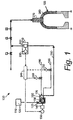
- Fig. 1 shows portions of a pneumatic conveying system 100 as may be described herein for use with at least a portion of a gasification system 105 and the like.
- the pneumatic conveying system 100 may include a coal source 110 with an amount of coal 120 therein.
- the coal source 110 may have any desired size or shape.
- the coal source 110 may contain any type of coal, petroleum coke, solid biomass, other solid carbonaceous fuels, or mixtures thereof (all of which are referred to as "coal 120").
- the coal 120 may be ground or otherwise prepared before use including being mixed with other ground particulate matter, such as non-carbonaceous mineral matter, that may be added to enhance the gasification characteristics of the coal in the gasifier.
- the pneumatic conveying system 100 may include a solids feeder 130 positioned downstream of and in communication with the coal source 110.
- the solids feeder 130 may be a rotary, converging channel solids pressurizing and metering device such as the Posimetric® Feeder, a particulate solids pump offered by the GE Energy Division of the General Electric Company of Schenectady, New York. Other types of feeders, solids pumps, or other types of conveyance devices may be used herein.
- the solids feeder 130 may be driven by a motor 140 with a speed controller 150.
- the solids feeder 130 may pressurize solids from atmospheric pressure at an inlet 125 of the feeder 130 to pressures well over about 70Kg/cm 2 (100psig) at a discharge 160 of the feeder 130.
- Other configurations may be used herein.
- the discharge 160 of the solids feeder 130 may be in communication with a flow of conveying gas 180, such as nitrogen, carbon dioxide, natural gas, or gas recycled from a downstream process. Other gases may also be used.
- the conveying gas 180 mixes with a flow of solids 170 from the discharge 160 of the solids feeder 130 and conveys the solids 170 downstream of the solids feeder 130 via a conduit 200.
- the solids feeder 130 also may be in communication with a flow of seal gas 190, such as nitrogen, which is injected into the solids feeder 130 in such a way as to prevent any conveying gas 180 from moving backwards through the feeder against the flow of solids 170 and leaking into the atmosphere via the inlet 125.
- the pneumatic conveying system 100 further may include a flow meter 210 positioned downstream of the solids feeder 130.
- the flow meter 210 may be of conventional design that is suitable for measuring the flow rate of pneumatically conveyed solids and may include a flow element 220, a flow transmitter 230, and/or other components. Other types of flow measurement devices may be used herein.
- the output of the flow meter 210 may be communicated to a controller 240.
- the controller 240 may be any type of conventional microprocessor and the like.
- the controller 240 may be in communication with the speed controller 150 of the solids feeder 130 as well as a number of flow control valves 250 in communication with the flow of the conveying gas 180 and the flow of the seal gas 190.
- the controller 240 controls the speed of the flow of solids 170 as may be desired. Any other type of control device may be used herein.
- the pneumatic conveying system 100 also may include a gasifier 260, only a portion of which is shown.
- the gasifier 260 may be positioned downstream of the flow meter 210.
- the gasifier 260 may be of conventional design and may include a fuel injector 270 or other type of intake device.
- the flow of solids 170 conveyed to the gasifier 260 reacts with oxygen, water, and possibly other reactants to generate a syngas product via well known, controlled chemical reactions.
- Fig. 2 shows a solids feeder 300 as may be described herein.
- the solids feeder 300 is an improvement upon the Posimetric® Feeder described above.
- the solids feeder 300 includes a feeder body 310.
- Two or more discs 320 may be mounted on a hub 325 which, in turn, in mounted on a rotating shaft 330 within the feeder body 310.
- the discs 320, the hub 325, and the rotating shaft 330 may be driven by the motor 140 with the speed controller 150 as is described above.
- Other types of drive means may be used herein.
- the inner surface of the body 310, the outer cylindrical surface of the hub 325 and the inner surfaces of the two discs 320 define a flow path 340 for the flow of solids 170 therethrough.
- the flow path 340 may extend from a low pressure inlet channel 350, around the outer surfaces of the hub 325, and to a high pressure outlet channel 360.
- a number of ports may be positioned about the outlet channel 360.
- one or more vent ports 370 for leakage gas and one or more injection ports 380 for a sealing gas such as nitrogen and the like are shown.
- Other types and configurations of the solids feeder 300 may be used herein.
- the outlet channel 360 of the solids feeder 300 may lead to a discharge port 400 as may be described herein.
- the discharge port 400 may be bolted or otherwise attached to the feeder body 310.
- the discharge port 400 may be in communication with the flow of conveying gas 180 or other type of conveying medium as will be described in more detail below.
- Figs. 3 and 4 show cross-sectional views of the discharge port 400.
- the discharge port 400 may be connected to the flow of conveying gas 180 via an inlet flange 410 and connected to the pneumatic conveying line 200 at an outlet flange 420.
- the discharge port 400 may have a flow channel 430 extending linearly from the inlet flange 410 to the outlet flange 420 and intersecting the outlet channel 360 such that the flow of conveying gas 180 picks up the solids emerging from the outlet channel 360 and transports them downstream via the pneumatic conveying line 200.
- the flow channel 430 of the discharge port 400 may have largely circular cross-sectional areas about the inlet flange 410 and the outlet flange 420, a circular inlet cross-sectional area 440 and a circular outlet cross-sectional area 445.
- the circular inlet cross-sectional area 440 and the circular outlet cross-sectional area 445 may or may not be identical.
- the flow channel 430 also may have a reduced cross-sectional area 450 about the outlet channel 360.
- the reduced cross-sectional area 450 may have a relatively narrow rectangular shape with rounded edges but any type of reduced cross-sectional area may be used herein.
- Transitional cross-sectional areas may be on both sides of the rectangular cross-sectional area 450 so as to connect the circular cross-sectional areas 440 and 445 with the rectangular cross-sectional area 450.
- a transitional inlet cross-sectional area 460 and a transitional outlet cross-sectional area 465 are shown.
- the transitional inlet cross-sectional area 460 and the transitional outlet cross-sectional area 465 may or may not be identical.
- the conveying gas 180 encounters the transitional inlet cross-sectional area 460 and the reduced cross-sectional area 450 of the flow channel 430.
- the reduced cross-sectional area 450 is much smaller than that of the circular inlet cross-sectional area 440 such that the velocity of the conveying gas 180 may be significantly increased as the conveying gas 180 crosses the outlet channel 360 and picks up the flow of solids 170.
- the conveying gas 180 thus conveys the flow of solids 170 through the outlet flange 420 and into the conveying line 200.
- any agglomerates of the coal 120 that emerge from the outlet channel 360 may be broken up (de-agglomerated) by the shearing action of the high velocity conveying gas 180 with the reduced cross-sectional area 450 and carried out with the more freely flowing solids also emerging from the outlet channel 360.
- the flow channel 430 extends through the transitional outlet cross-sectional area 465 and into the circular outlet cross-sectional area 445 about the outlet flange 420, the increase in the cross-sectional area produces turbulent eddies.
- Such a turbulent flow may enhance the mixing of the conveying gas 180 and the entrained solids (both the more freely flowing solids and the de-agglomerated solids) within the flow of the solids 170 so as to minimize flow rate fluctuations through the discharge port 400.
- Fig. 5 shows a further embodiment of a discharge port 470 as may be described herein.
- the discharge port 470 may be similar to the discharge port 400 described above but with a variably reduced cross-sectional area 480.
- a moveable plate 490 may be positioned within the variably reduced cross-sectional area 480 of the flow channel 430.
- Other types of structures may be used herein to vary the cross-sectional area of the flow channel 430.
- the movable plate 490 may be positioned on a shaft 500 or other type of structure so as to vary the position of the moveable plate 490 within the variably reduced cross-sectional area 480 of the flow channel 430.
- the moveable plate 490 and the shaft 500 may be positioned via a motor, other types of drive means, or manually set.
- the moveable plate 490 When the moveable plate 490 is lowered into the variable reduced cross-sectional area 480, the velocity of the flow of the conveying gas 180 therethrough may increase. Conversely, raising the moveable plate 490 will decrease the velocity of the flow of the conveyor gas 180 therethrough. The movable plate 490 thus may maintain a relatively constant high velocity of the conveying gas 180 even if the flow rate through the solids feeder 300 is reduced, such as during startup and the like. Other configurations may be used herein.
- Figs. 6 and 7 show a further embodiment of a discharge port 510 as may be described herein.
- the discharge port 510 may be largely similar to the discharge port 400 described above, but with the addition of one or more agitators 520 positioned within the reduced cross-sectional area 450 of the flow channel 430. Any number of agitators 520 may be used.
- the agitators 520 may include a number of blades 530 positioned on a shaft 540 for rotation therewith. Any shape or number of blades 530 may be used.
- the shafts 540 may be motor driven and/or may be driven by the velocity of the flow of the conveying gas 180 therethrough.
- the blades 530 of the agitators 520 may continuously sweep within the reduced cross-sectional area 450 of the flow channel 430.
- the agitators 520 thus assist in the break up of any aggregates within the flow of solids 170 therethrough. Enough clearance between the blades 530 and the walls of the reduced cross-sectional area 450 of the flow channel 430 may ensure that the flow of the conveying gas 180 can always flow therethrough without being blocked. Other types of agitating devices may be used herein.
- the use of the discharge port 400, 470, or 510 on the solids feeder 300 thus aids in the break up of any aggregates in the flow of solids 170 as the flow reaches the end of the discharge channel 360 and enters the pneumatic conveying line 200.
- the flow of solids 170 thus is smoothed out and hence provides improved solids flow rate control.
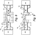
- Figs. 8 and 9 show a further embodiment of a discharge port 550 as may be described herein.
- the discharge port 550 may be largely similar to the discharge port 400 or the other discharge ports described above.
- the discharge port 550 also may include a downstream check valve 560 positioned downstream of the reduced cross-sectional area 450 of the flow channel 430 and upstream of the outlet flange 420 and an upstream check valve 570 positioned upstream of the reduced cross-sectional area 450 of the flow channel 430 and downstream of the inlet flange 410. Other positions may be used herein.
- the downstream check valve 560 may be a flapper valve 580 and the like. Other types of valves may be used herein. In the event of a backflow condition, the downstream check valve 560 may drop down to shut the flow channel 430 and then may be held in place by the pressure of the back flow.
- the downstream check valve 560 thus may be smaller in size than known check valves that were generally positioned about the outlet channel 360 such that the check valve had to close on top of the flow of solids 170 rising therein.
- the location of the downstream check valve 560 just downstream of the reduced cross-sectional area 450 of the flow channel 430 ensures that the check valve 560 operates under dilute phase flow conditions as opposed to having to operate in conditions where the solids are compacted within the outlet channel 360.
- the downstream check valve 560 may close more tightly given this dilute phase while all of the back flow pressure may be concentrated in a smaller area.
- the upstream check valve 570 may include a butterfly check valve 590 and the like.
- the butterfly check valve 590 may be spring loaded. Other types of valves may be used herein.
- the upstream check valve 590 thus prevents the flow of solids 170 from entering into the source of the flow of conveying gas 180.
- the discharge port 550 also may include a downstream shutoff valve 600 positioned about the outlet flange 420 and upstream shutoff valve 610 positioned about the inlet flange 410.
- the shutoff valves 600, 610 may include a ball valve, a knife gate valve, and/or other types of valves in any orientation so as to isolate the discharge port 550.
- the solids feeder 300 generally includes one or more nitrogen injection ports 380 positioned about the outlet channel 360.
- nitrogen or other types of inert gasses may be injected therein so as to ensure that any gas leakage back through the flow path 340 may be inert as opposed to toxic or flammable.
- One option is the use of an outlet channel distribution ring 620 positioned about the outlet channel 360.
- the outlet channel distribution ring 620 may include a number of layers including an injection layer 630 with a number of small diameter holes 640 positioned therein. The injection holes 640 may be angled in the direction of the flow of solids so as to minimize plugging.
- the injection holes 640 may be made by laser sintering techniques and other types of manufacturing techniques.
- a second layer may be a sintered metal porous layer 650.
- the sintered metal porous layer 650 may provide support for the injection layer 630 while also allowing the nitrogen or other gas to pass therethrough.
- the third layer may be an open distribution channel layer 660.
- the open distribution channel layer 660 may convey the nitrogen of other gas from the injection sport 380. Other configurations may be used herein.
- a further alternative may be a discharge port distribution ring 670.
- the discharge port distribution ring 670 may be positioned or incorporated into the bottom surface of the discharge port 400.
- Fig. 11 shows an example of the discharge port distribution ring 670.
- the discharge port distribution ring 670 may include an injection layer 680 with a number of holes 690 positioned therein.
- the injection layer 680 may be surrounded by a distribution channel 700.
- the distribution channel 700 may be in communication with the injection port 380.
- the use of the discharge port distribution ring 670 may provide easier access as compared to the outlet channel distribution ring 620.
- the discharge port distribution ring 670 also may assist in breaking up aggregates in the flow of solids 170 passing through the discharge port 400.
- Other configurations may be used herein.
Landscapes
- Engineering & Computer Science (AREA)
- Mechanical Engineering (AREA)
- Chemical & Material Sciences (AREA)
- Combustion & Propulsion (AREA)
- General Engineering & Computer Science (AREA)
- Filling Or Emptying Of Bunkers, Hoppers, And Tanks (AREA)
- Feeding, Discharge, Calcimining, Fusing, And Gas-Generation Devices (AREA)
Claims (15)
- Dispositif d'alimentation en solides (300) en communication avec un écoulement de solides et un écoulement d'un fluide de transport, le dispositif d'alimentation en solides (300) comprenant:un corps de dispositif d'alimentation (310), au moins un disque (320), un moyeu (325) et un arbre rotatif (330), dans lequel le disque (320) est monté sur le moyeu (325), et dans lequel le moyeu (325) est monté sur l'arbre rotatif (330) à l'intérieur du corps de dispositif d'alimentation (310);un canal de sortie (360) comprenant l'écoulement de solides dans celui-ci; etun port de décharge (400) en communication avec le canal de sortie (360);le port de décharge (400) comprenant en outre une entrée en communication avec l'écoulement du fluide de transport et un canal d'écoulement (430); etdans lequel le canal d'écoulement (430) présente une surface de section transversale réduite de façon variable (450) autour du canal de sortie (360) comparativement à l'entrée, et dans lequel le canal d'écoulement comprend une plaque mobile dans celui-ci.
- Dispositif d'alimentation en solides selon la revendication 1, dans lequel l'entrée présente une surface de section transversale d'entrée circulaire (440), et dans lequel la surface de section transversale d'entrée circulaire est plus grande que la surface de section transversale réduite (450).
- Dispositif d'alimentation en solides selon la revendication 1, dans lequel le port de décharge (400) comprend une sortie en communication avec une ligne de transport.
- Dispositif d'alimentation en solides selon la revendication 3, dans lequel la sortie présente une surface de section transversale de sortie circulaire (445), et dans lequel la surface de section transversale de sortie circulaire est plus grande que la surface de section transversale réduite (450).
- Dispositif d'alimentation en solides selon la revendication 1, dans lequel la surface de section transversale réduite (450) du canal d'écoulement (430) présente une surface de section transversale rectangulaire.
- Dispositif d'alimentation en solides selon la revendication 1, dans lequel le canal d'écoulement (430) présente une surface de section transversale d'entrée de transition (460) et une surface de section transversale de sortie de transition (465).
- Dispositif d'alimentation en solides selon la revendication 1, dans lequel le canal d'écoulement (430) comprend un ou plusieurs agitateur(s) (520) dans celui-ci, et dans lequel, de préférence, ledit/lesdits un ou plusieurs agitateur(s) comprend(-nent) une pluralité de pales.
- Dispositif d'alimentation en solides selon la revendication 1, comprenant en outre un clapet antiretour aval (560) positionné en aval du canal d'écoulement, et un clapet antiretour amont (570) positionné en amont du canal d'écoulement.
- Dispositif d'alimentation en solides selon la revendication 8, dans lequel:le clapet antiretour aval (560) comprend un clapet antiretour à battant, et/oule clapet antiretour amont (570) comprend un clapet antiretour à papillon.
- Dispositif d'alimentation en solides selon la revendication 1, comprenant en outre une ou plusieurs soupape(s) d'arrêt (600, 610) positionnée(s) autour du port de décharge.
- Dispositif d'alimentation en solides selon la revendication 1, dans lequel le canal de sortie (360) comprend un anneau de distribution (620) et dans lequel, de préférence, l'anneau de distribution (620) comprend une couche d'injection, une couche poreuse et une couche de canal de distribution ouverte.
- Dispositif d'alimentation en solides selon la revendication 1, dans lequel le port de décharge (400) comprend un anneau de distribution (670), et dans lequel, de préférence, l'anneau de distribution (670) comprend une couche d'injection (680) et un canal de distribution (700).
- Dispositif d'alimentation en solides selon la revendication 1, dans lequel deux ou plus de deux disques (320) sont prévus.
- Procédé pour uniformiser un écoulement de solides sortant d'un dispositif d'alimentation en solides (300) selon la revendication 1 par l'intermédiaire d'un écoulement d'un gaz de transport, comprenant les étapes suivantes:amener l'écoulement du gaz de transport à un port de décharge (400) du dispositif d'alimentation en solides (300);réduire la surface de section transversale d'un canal d'écoulement (430) à travers le port de décharge (400) de manière à augmenter la vitesse de l'écoulement du gaz de transport;fusionner l'écoulement de solides et l'écoulement du gaz de transport dans le canal d'écoulement (430); etcasser l'écoulement de solides par une action de cisaillement de l'écoulement du gaz de transport.
- Procédé selon la revendication 14, comprenant en outre l'augmentation de la surface de section transversale du port de décharge (400) en aval du canal d'écoulement (430) afin de créer des courants turbulents dans le but de renforcer encore le mélange de l'écoulement de solides et de l'écoulement de gaz de transport et d'uniformiser l'écoulement de solides.
Applications Claiming Priority (2)
| Application Number | Priority Date | Filing Date | Title |
|---|---|---|---|
| US12/915,556 US8882400B2 (en) | 2010-10-29 | 2010-10-29 | Solids feeder discharge port |
| PCT/US2011/049297 WO2012057909A2 (fr) | 2010-10-29 | 2011-08-26 | Orifice d'évacuation de dispositif d'alimentation en solides |
Publications (2)
| Publication Number | Publication Date |
|---|---|
| EP2632832A2 EP2632832A2 (fr) | 2013-09-04 |
| EP2632832B1 true EP2632832B1 (fr) | 2018-04-11 |
Family
ID=44720111
Family Applications (1)
| Application Number | Title | Priority Date | Filing Date |
|---|---|---|---|
| EP11761742.3A Not-in-force EP2632832B1 (fr) | 2010-10-29 | 2011-08-26 | Dispositif d'alimentation en solides |
Country Status (6)
| Country | Link |
|---|---|
| US (1) | US8882400B2 (fr) |
| EP (1) | EP2632832B1 (fr) |
| KR (1) | KR101779242B1 (fr) |
| CN (1) | CN103492808B (fr) |
| AU (1) | AU2011320939B2 (fr) |
| WO (1) | WO2012057909A2 (fr) |
Families Citing this family (5)
| Publication number | Priority date | Publication date | Assignee | Title |
|---|---|---|---|---|
| US9109731B2 (en) * | 2012-11-26 | 2015-08-18 | General Electric Company | System and method for conveying solids through an outlet pipe |
| US9784080B2 (en) | 2013-04-08 | 2017-10-10 | Baker Hughes Incorporated | Tubless proppant blending system for high and low pressure blending |
| US9334720B2 (en) | 2013-04-08 | 2016-05-10 | Baker Hughes Incorporated | Tubless proppant blending system for high and low pressure blending |
| EP4209263A1 (fr) * | 2022-01-10 | 2023-07-12 | JSP International SARL | Appareil de transport de particules de polyoléfine |
| EP4209436B1 (fr) * | 2022-01-10 | 2024-05-22 | FOX Velution GmbH | Appareil de transport de particules de polymères |
Citations (4)
| Publication number | Priority date | Publication date | Assignee | Title |
|---|---|---|---|---|
| US4019783A (en) * | 1974-08-06 | 1977-04-26 | Lutz Tilo Kayser | Process and apparatus for continuously conveying particulate material |
| US4302481A (en) * | 1978-11-14 | 1981-11-24 | Gema Ag | Spray method and spray device, particularly for the spray-coating of articles with powder |
| US4480947A (en) * | 1981-06-17 | 1984-11-06 | Hideo Nagasaka | Powder flow rate measuring apparatus |
| US20070158476A1 (en) * | 2003-07-04 | 2007-07-12 | Keith Laidler | Nozzle arrangements |
Family Cites Families (32)
| Publication number | Priority date | Publication date | Assignee | Title |
|---|---|---|---|---|
| US1908220A (en) * | 1931-12-07 | 1933-05-09 | Frank D Chapman | Hydraulic conveyer |
| DE1016397B (de) | 1954-07-05 | 1957-09-26 | Peters Ag Claudius | Pneumatische Staubzuteilvorrichtung |
| US4168864A (en) * | 1975-02-21 | 1979-09-25 | Air Konvey Company | Apparatus for conveying particulate matter |
| US4002372A (en) | 1975-12-01 | 1977-01-11 | General Shale Products Corporation | Pulverulent material metering and delivery system and method |
| US4416610A (en) * | 1980-03-14 | 1983-11-22 | Hydroil, Inc. | Water-in-oil emulsifier and oil-burner boiler system incorporating such emulsifier |
| US4546902A (en) * | 1981-11-02 | 1985-10-15 | Anderson James Y | Apparatus for controlling the rate of fluent material |
| EP0312641A1 (fr) * | 1987-10-23 | 1989-04-26 | "Harrier" Gmbh Gesellschaft Für Den Vertrieb Medizinischer Und Technischer Geräte | Procédé pour mélanger du carburant et de l'eau, dispositif pour mettre en oeuvre ce procédé et mélange carburant-eau |
| US5240326A (en) * | 1990-12-28 | 1993-08-31 | Environmental Consideration, Ltd. | Chemical handling and mixing system |
| DE4201665C2 (de) * | 1992-01-22 | 1993-10-28 | Wagner International Ag Altsta | Pulver-Injektor |
| DE4419987A1 (de) * | 1994-06-08 | 1996-02-29 | Gema Volstatic Ag | Injektor-Fördervorrichtung zur pneumatischen Förderung von Pulver |
| US5722801A (en) * | 1995-12-21 | 1998-03-03 | The Young Industries, Inc. | Material conveying system with flow rate control |
| DE19728595C1 (de) * | 1997-07-04 | 1998-09-17 | Daimler Benz Aerospace Airbus | Injektorluftauslaß zur Temperatur- und Rauchgasüberwachung |
| US6213289B1 (en) | 1997-11-24 | 2001-04-10 | Stamet, Incorporation | Multiple channel system, apparatus and method for transporting particulate material |
| US6488773B1 (en) * | 1999-02-19 | 2002-12-03 | Plastic Stuff, Llc | Apparatus and method for spraying polymer |
| US6885114B2 (en) * | 1999-10-05 | 2005-04-26 | Access Business Group International, Llc | Miniature hydro-power generation system |
| DE10027873C1 (de) * | 2000-06-06 | 2002-02-07 | Festo Ag & Co | Pneumatische Drucksteuereinrichtung |
| US6890093B2 (en) * | 2000-08-07 | 2005-05-10 | Nanostream, Inc. | Multi-stream microfludic mixers |
| CN2505716Y (zh) * | 2001-11-09 | 2002-08-14 | 陆纪清 | 全负压煤粉混合器 |
| DE10213275C1 (de) * | 2002-03-25 | 2003-12-24 | Wagner Ag Altstaetten J | Injektor für eine Pulverbeschichtungsanlage |
| US6719500B2 (en) * | 2002-08-20 | 2004-04-13 | The Young Industries, Inc. | System for pneumatically conveying bulk particulate materials |
| EP1637302B1 (fr) * | 2003-05-26 | 2011-07-13 | Yoshino Gypsum Co., Ltd. | Mélangeurs, procédés de mélange et usage de ces mélangeurs pour produire une plaque de gypse |
| US6974279B2 (en) * | 2003-10-07 | 2005-12-13 | Trinity Inudstrial Corporation | Ejector, fine solid piece recovery apparatus and fluid conveyor |
| US7252429B2 (en) * | 2004-06-17 | 2007-08-07 | John David Yungblut | Rotary fluid agitator |
| DE202004019438U1 (de) * | 2004-12-16 | 2005-02-10 | J. Wagner Ag | Pulverfördervorrichtung und Fangdüse für die Pulverfördervorrichtung |
| JP5021999B2 (ja) | 2006-10-20 | 2012-09-12 | 三菱重工業株式会社 | 難燃性燃料用バーナ |
| US7311474B1 (en) * | 2007-01-04 | 2007-12-25 | Itswa Co., Ltd. | Pellet loader |
| EP1958899B1 (fr) * | 2007-02-16 | 2013-08-21 | J. Wagner AG | Dispositif d'alimentation de fluide |
| US8992641B2 (en) | 2007-10-26 | 2015-03-31 | General Electric Company | Fuel feed system for a gasifier |
| JP5260034B2 (ja) | 2007-11-30 | 2013-08-14 | 三菱重工業株式会社 | 粉体分離装置及び固体燃料用バーナ |
| FR2931165B1 (fr) * | 2008-05-13 | 2010-11-26 | Cmi Thermline Services | Dispositif de soufflage de gaz sur une face d'un materiau en bande en defilement |
| US8220982B2 (en) * | 2008-07-22 | 2012-07-17 | Terex Usa, Llc | Energy efficient asphalt plant |
| JP5691195B2 (ja) * | 2010-03-01 | 2015-04-01 | ソニー株式会社 | マイクロチップ及び微小粒子分析装置 |
-
2010
- 2010-10-29 US US12/915,556 patent/US8882400B2/en active Active
-
2011
- 2011-08-26 WO PCT/US2011/049297 patent/WO2012057909A2/fr not_active Ceased
- 2011-08-26 KR KR1020137010805A patent/KR101779242B1/ko active Active
- 2011-08-26 EP EP11761742.3A patent/EP2632832B1/fr not_active Not-in-force
- 2011-08-26 CN CN201180052960.7A patent/CN103492808B/zh not_active Expired - Fee Related
- 2011-08-26 AU AU2011320939A patent/AU2011320939B2/en not_active Ceased
Patent Citations (4)
| Publication number | Priority date | Publication date | Assignee | Title |
|---|---|---|---|---|
| US4019783A (en) * | 1974-08-06 | 1977-04-26 | Lutz Tilo Kayser | Process and apparatus for continuously conveying particulate material |
| US4302481A (en) * | 1978-11-14 | 1981-11-24 | Gema Ag | Spray method and spray device, particularly for the spray-coating of articles with powder |
| US4480947A (en) * | 1981-06-17 | 1984-11-06 | Hideo Nagasaka | Powder flow rate measuring apparatus |
| US20070158476A1 (en) * | 2003-07-04 | 2007-07-12 | Keith Laidler | Nozzle arrangements |
Also Published As
| Publication number | Publication date |
|---|---|
| CN103492808B (zh) | 2016-01-27 |
| US8882400B2 (en) | 2014-11-11 |
| US20120107058A1 (en) | 2012-05-03 |
| CN103492808A (zh) | 2014-01-01 |
| KR101779242B1 (ko) | 2017-09-18 |
| EP2632832A2 (fr) | 2013-09-04 |
| WO2012057909A3 (fr) | 2013-10-10 |
| AU2011320939A1 (en) | 2013-05-02 |
| KR20130139272A (ko) | 2013-12-20 |
| WO2012057909A2 (fr) | 2012-05-03 |
| AU2011320939B2 (en) | 2016-07-28 |
Similar Documents
| Publication | Publication Date | Title |
|---|---|---|
| EP2633234B1 (fr) | Dispositif de mélange à contre-courant destiné à des systèmes de transport pneumatiques | |
| EP2632832B1 (fr) | Dispositif d'alimentation en solides | |
| CN101909738B (zh) | 向加压反应器供应微粒固体材料的方法 | |
| CN101323398B (zh) | 气力输送料罐流量调节装置及控制方法 | |
| EP2431310B1 (fr) | Système comportant une pompe pour le transfert de matières solides et un passage de contrôle thermique | |
| US9181046B2 (en) | System and method to supply a solid feedstock to a solids feeder | |
| CN102689777B (zh) | 分段式固体给料泵 | |
| CN201849945U (zh) | 一种打包燃料的密封打散供料装置 | |
| US9156631B2 (en) | Multi-stage solids feeder system and method | |
| US9926939B2 (en) | System for drawing solid feed into and/or out of a solid feed pump | |
| CN202625253U (zh) | 粉料输送稳定装置 | |
| CN110229700A (zh) | 多元混合生物质气化正压给料系统 | |
| US20120096769A1 (en) | Solid feed systems for elevated pressure processes, gasification systems and related methods | |
| CN201002890Y (zh) | 一种新型可调粉量气力输送喷射装置 | |
| CN116534591A (zh) | 粉体气力输送泵 | |
| JP2004091570A (ja) | 粉粒体供給装置 | |
| CN221991830U (zh) | 一种正压煤粉预燃装置用煤粉输送系统 | |
| CN223774658U (zh) | 一种制氧机用氧气浓度调节装置 | |
| CN218860652U (zh) | 一种地上煤气化炉灰渣连续输送处理系统 | |
| CN221274560U (zh) | 一种气力输送泵 | |
| CN117844537A (zh) | 一种地上煤气化炉灰渣连续输送处理系统 | |
| JP2004210520A (ja) | 粉体の空気輸送装置 | |
| CN115490005A (zh) | 加压出料装置及其应用 |
Legal Events
| Date | Code | Title | Description |
|---|---|---|---|
| PUAI | Public reference made under article 153(3) epc to a published international application that has entered the european phase |
Free format text: ORIGINAL CODE: 0009012 |
|
| AK | Designated contracting states |
Kind code of ref document: A2 Designated state(s): AL AT BE BG CH CY CZ DE DK EE ES FI FR GB GR HR HU IE IS IT LI LT LU LV MC MK MT NL NO PL PT RO RS SE SI SK SM TR |
|
| AX | Request for extension of the european patent |
Extension state: BA ME |
|
| R17D | Deferred search report published (corrected) |
Effective date: 20131010 |
|
| 17P | Request for examination filed |
Effective date: 20140410 |
|
| RBV | Designated contracting states (corrected) |
Designated state(s): AL AT BE BG CH CY CZ DE DK EE ES FI FR GB GR HR HU IE IS IT LI LT LU LV MC MK MT NL NO PL PT RO RS SE SI SK SM TR |
|
| DAX | Request for extension of the european patent (deleted) | ||
| 17Q | First examination report despatched |
Effective date: 20170315 |
|
| REG | Reference to a national code |
Ref country code: DE Ref legal event code: R079 Ref document number: 602011047422 Country of ref document: DE Free format text: PREVIOUS MAIN CLASS: B65G0053660000 Ipc: F23K0003020000 |
|
| GRAP | Despatch of communication of intention to grant a patent |
Free format text: ORIGINAL CODE: EPIDOSNIGR1 |
|
| RIC1 | Information provided on ipc code assigned before grant |
Ipc: F23N 1/00 20060101ALI20171011BHEP Ipc: F23K 3/02 20060101AFI20171011BHEP |
|
| INTG | Intention to grant announced |
Effective date: 20171030 |
|
| GRAS | Grant fee paid |
Free format text: ORIGINAL CODE: EPIDOSNIGR3 |
|
| GRAA | (expected) grant |
Free format text: ORIGINAL CODE: 0009210 |
|
| AK | Designated contracting states |
Kind code of ref document: B1 Designated state(s): AL AT BE BG CH CY CZ DE DK EE ES FI FR GB GR HR HU IE IS IT LI LT LU LV MC MK MT NL NO PL PT RO RS SE SI SK SM TR |
|
| REG | Reference to a national code |
Ref country code: GB Ref legal event code: FG4D |
|
| REG | Reference to a national code |
Ref country code: CH Ref legal event code: EP |
|
| REG | Reference to a national code |
Ref country code: AT Ref legal event code: REF Ref document number: 988436 Country of ref document: AT Kind code of ref document: T Effective date: 20180415 |
|
| REG | Reference to a national code |
Ref country code: IE Ref legal event code: FG4D |
|
| REG | Reference to a national code |
Ref country code: DE Ref legal event code: R096 Ref document number: 602011047422 Country of ref document: DE |
|
| REG | Reference to a national code |
Ref country code: NL Ref legal event code: MP Effective date: 20180411 |
|
| REG | Reference to a national code |
Ref country code: LT Ref legal event code: MG4D |
|
| PG25 | Lapsed in a contracting state [announced via postgrant information from national office to epo] |
Ref country code: NL Free format text: LAPSE BECAUSE OF FAILURE TO SUBMIT A TRANSLATION OF THE DESCRIPTION OR TO PAY THE FEE WITHIN THE PRESCRIBED TIME-LIMIT Effective date: 20180411 |
|
| PG25 | Lapsed in a contracting state [announced via postgrant information from national office to epo] |
Ref country code: LT Free format text: LAPSE BECAUSE OF FAILURE TO SUBMIT A TRANSLATION OF THE DESCRIPTION OR TO PAY THE FEE WITHIN THE PRESCRIBED TIME-LIMIT Effective date: 20180411 Ref country code: PL Free format text: LAPSE BECAUSE OF FAILURE TO SUBMIT A TRANSLATION OF THE DESCRIPTION OR TO PAY THE FEE WITHIN THE PRESCRIBED TIME-LIMIT Effective date: 20180411 Ref country code: SE Free format text: LAPSE BECAUSE OF FAILURE TO SUBMIT A TRANSLATION OF THE DESCRIPTION OR TO PAY THE FEE WITHIN THE PRESCRIBED TIME-LIMIT Effective date: 20180411 Ref country code: NO Free format text: LAPSE BECAUSE OF FAILURE TO SUBMIT A TRANSLATION OF THE DESCRIPTION OR TO PAY THE FEE WITHIN THE PRESCRIBED TIME-LIMIT Effective date: 20180711 Ref country code: ES Free format text: LAPSE BECAUSE OF FAILURE TO SUBMIT A TRANSLATION OF THE DESCRIPTION OR TO PAY THE FEE WITHIN THE PRESCRIBED TIME-LIMIT Effective date: 20180411 Ref country code: AL Free format text: LAPSE BECAUSE OF FAILURE TO SUBMIT A TRANSLATION OF THE DESCRIPTION OR TO PAY THE FEE WITHIN THE PRESCRIBED TIME-LIMIT Effective date: 20180411 Ref country code: FI Free format text: LAPSE BECAUSE OF FAILURE TO SUBMIT A TRANSLATION OF THE DESCRIPTION OR TO PAY THE FEE WITHIN THE PRESCRIBED TIME-LIMIT Effective date: 20180411 Ref country code: BG Free format text: LAPSE BECAUSE OF FAILURE TO SUBMIT A TRANSLATION OF THE DESCRIPTION OR TO PAY THE FEE WITHIN THE PRESCRIBED TIME-LIMIT Effective date: 20180711 |
|
| PG25 | Lapsed in a contracting state [announced via postgrant information from national office to epo] |
Ref country code: RS Free format text: LAPSE BECAUSE OF FAILURE TO SUBMIT A TRANSLATION OF THE DESCRIPTION OR TO PAY THE FEE WITHIN THE PRESCRIBED TIME-LIMIT Effective date: 20180411 Ref country code: HR Free format text: LAPSE BECAUSE OF FAILURE TO SUBMIT A TRANSLATION OF THE DESCRIPTION OR TO PAY THE FEE WITHIN THE PRESCRIBED TIME-LIMIT Effective date: 20180411 Ref country code: LV Free format text: LAPSE BECAUSE OF FAILURE TO SUBMIT A TRANSLATION OF THE DESCRIPTION OR TO PAY THE FEE WITHIN THE PRESCRIBED TIME-LIMIT Effective date: 20180411 Ref country code: GR Free format text: LAPSE BECAUSE OF FAILURE TO SUBMIT A TRANSLATION OF THE DESCRIPTION OR TO PAY THE FEE WITHIN THE PRESCRIBED TIME-LIMIT Effective date: 20180712 |
|
| REG | Reference to a national code |
Ref country code: AT Ref legal event code: MK05 Ref document number: 988436 Country of ref document: AT Kind code of ref document: T Effective date: 20180411 |
|
| PG25 | Lapsed in a contracting state [announced via postgrant information from national office to epo] |
Ref country code: PT Free format text: LAPSE BECAUSE OF FAILURE TO SUBMIT A TRANSLATION OF THE DESCRIPTION OR TO PAY THE FEE WITHIN THE PRESCRIBED TIME-LIMIT Effective date: 20180813 |
|
| REG | Reference to a national code |
Ref country code: DE Ref legal event code: R097 Ref document number: 602011047422 Country of ref document: DE |
|
| PG25 | Lapsed in a contracting state [announced via postgrant information from national office to epo] |
Ref country code: AT Free format text: LAPSE BECAUSE OF FAILURE TO SUBMIT A TRANSLATION OF THE DESCRIPTION OR TO PAY THE FEE WITHIN THE PRESCRIBED TIME-LIMIT Effective date: 20180411 Ref country code: DK Free format text: LAPSE BECAUSE OF FAILURE TO SUBMIT A TRANSLATION OF THE DESCRIPTION OR TO PAY THE FEE WITHIN THE PRESCRIBED TIME-LIMIT Effective date: 20180411 Ref country code: SK Free format text: LAPSE BECAUSE OF FAILURE TO SUBMIT A TRANSLATION OF THE DESCRIPTION OR TO PAY THE FEE WITHIN THE PRESCRIBED TIME-LIMIT Effective date: 20180411 Ref country code: EE Free format text: LAPSE BECAUSE OF FAILURE TO SUBMIT A TRANSLATION OF THE DESCRIPTION OR TO PAY THE FEE WITHIN THE PRESCRIBED TIME-LIMIT Effective date: 20180411 Ref country code: CZ Free format text: LAPSE BECAUSE OF FAILURE TO SUBMIT A TRANSLATION OF THE DESCRIPTION OR TO PAY THE FEE WITHIN THE PRESCRIBED TIME-LIMIT Effective date: 20180411 Ref country code: RO Free format text: LAPSE BECAUSE OF FAILURE TO SUBMIT A TRANSLATION OF THE DESCRIPTION OR TO PAY THE FEE WITHIN THE PRESCRIBED TIME-LIMIT Effective date: 20180411 |
|
| PLBE | No opposition filed within time limit |
Free format text: ORIGINAL CODE: 0009261 |
|
| STAA | Information on the status of an ep patent application or granted ep patent |
Free format text: STATUS: NO OPPOSITION FILED WITHIN TIME LIMIT |
|
| PG25 | Lapsed in a contracting state [announced via postgrant information from national office to epo] |
Ref country code: SM Free format text: LAPSE BECAUSE OF FAILURE TO SUBMIT A TRANSLATION OF THE DESCRIPTION OR TO PAY THE FEE WITHIN THE PRESCRIBED TIME-LIMIT Effective date: 20180411 Ref country code: IT Free format text: LAPSE BECAUSE OF FAILURE TO SUBMIT A TRANSLATION OF THE DESCRIPTION OR TO PAY THE FEE WITHIN THE PRESCRIBED TIME-LIMIT Effective date: 20180411 |
|
| 26N | No opposition filed |
Effective date: 20190114 |
|
| PG25 | Lapsed in a contracting state [announced via postgrant information from national office to epo] |
Ref country code: MC Free format text: LAPSE BECAUSE OF FAILURE TO SUBMIT A TRANSLATION OF THE DESCRIPTION OR TO PAY THE FEE WITHIN THE PRESCRIBED TIME-LIMIT Effective date: 20180411 |
|
| REG | Reference to a national code |
Ref country code: CH Ref legal event code: PL |
|
| GBPC | Gb: european patent ceased through non-payment of renewal fee |
Effective date: 20180826 |
|
| PG25 | Lapsed in a contracting state [announced via postgrant information from national office to epo] |
Ref country code: LU Free format text: LAPSE BECAUSE OF NON-PAYMENT OF DUE FEES Effective date: 20180826 Ref country code: CH Free format text: LAPSE BECAUSE OF NON-PAYMENT OF DUE FEES Effective date: 20180831 Ref country code: LI Free format text: LAPSE BECAUSE OF NON-PAYMENT OF DUE FEES Effective date: 20180831 |
|
| REG | Reference to a national code |
Ref country code: BE Ref legal event code: MM Effective date: 20180831 |
|
| PG25 | Lapsed in a contracting state [announced via postgrant information from national office to epo] |
Ref country code: SI Free format text: LAPSE BECAUSE OF FAILURE TO SUBMIT A TRANSLATION OF THE DESCRIPTION OR TO PAY THE FEE WITHIN THE PRESCRIBED TIME-LIMIT Effective date: 20180411 |
|
| PG25 | Lapsed in a contracting state [announced via postgrant information from national office to epo] |
Ref country code: BE Free format text: LAPSE BECAUSE OF NON-PAYMENT OF DUE FEES Effective date: 20180831 Ref country code: FR Free format text: LAPSE BECAUSE OF NON-PAYMENT OF DUE FEES Effective date: 20180831 |
|
| PG25 | Lapsed in a contracting state [announced via postgrant information from national office to epo] |
Ref country code: GB Free format text: LAPSE BECAUSE OF NON-PAYMENT OF DUE FEES Effective date: 20180826 |
|
| PG25 | Lapsed in a contracting state [announced via postgrant information from national office to epo] |
Ref country code: MT Free format text: LAPSE BECAUSE OF NON-PAYMENT OF DUE FEES Effective date: 20180826 |
|
| PG25 | Lapsed in a contracting state [announced via postgrant information from national office to epo] |
Ref country code: TR Free format text: LAPSE BECAUSE OF FAILURE TO SUBMIT A TRANSLATION OF THE DESCRIPTION OR TO PAY THE FEE WITHIN THE PRESCRIBED TIME-LIMIT Effective date: 20180411 |
|
| REG | Reference to a national code |
Ref country code: DE Ref legal event code: R081 Ref document number: 602011047422 Country of ref document: DE Owner name: AIR PRODUCTS AND CHEMICALS, INC., ALLENTOWN, US Free format text: FORMER OWNER: GENERAL ELECTRIC COMPANY, SCHENECTADY, N.Y., US Ref country code: DE Ref legal event code: R081 Ref document number: 602011047422 Country of ref document: DE Owner name: AIR PRODUCTS AND CHEMICALS, INC., ALLENTOWN, US Free format text: FORMER OWNER: GENERAL ELECTRIC COMPANY, SCHENECTADY, NY, US |
|
| PG25 | Lapsed in a contracting state [announced via postgrant information from national office to epo] |
Ref country code: HU Free format text: LAPSE BECAUSE OF FAILURE TO SUBMIT A TRANSLATION OF THE DESCRIPTION OR TO PAY THE FEE WITHIN THE PRESCRIBED TIME-LIMIT; INVALID AB INITIO Effective date: 20110826 |
|
| PG25 | Lapsed in a contracting state [announced via postgrant information from national office to epo] |
Ref country code: CY Free format text: LAPSE BECAUSE OF FAILURE TO SUBMIT A TRANSLATION OF THE DESCRIPTION OR TO PAY THE FEE WITHIN THE PRESCRIBED TIME-LIMIT Effective date: 20180411 Ref country code: IE Free format text: LAPSE BECAUSE OF NON-PAYMENT OF DUE FEES Effective date: 20180826 Ref country code: MK Free format text: LAPSE BECAUSE OF NON-PAYMENT OF DUE FEES Effective date: 20180411 |
|
| PG25 | Lapsed in a contracting state [announced via postgrant information from national office to epo] |
Ref country code: IS Free format text: LAPSE BECAUSE OF FAILURE TO SUBMIT A TRANSLATION OF THE DESCRIPTION OR TO PAY THE FEE WITHIN THE PRESCRIBED TIME-LIMIT Effective date: 20180811 |
|
| P01 | Opt-out of the competence of the unified patent court (upc) registered |
Effective date: 20230515 |
|
| PGFP | Annual fee paid to national office [announced via postgrant information from national office to epo] |
Ref country code: DE Payment date: 20240702 Year of fee payment: 14 |
|
| REG | Reference to a national code |
Ref country code: DE Ref legal event code: R119 Ref document number: 602011047422 Country of ref document: DE |