EP2632841B1 - Absolutpositionsbestimmung bei antriebssystemen - Google Patents
Absolutpositionsbestimmung bei antriebssystemen Download PDFInfo
- Publication number
- EP2632841B1 EP2632841B1 EP11808628.9A EP11808628A EP2632841B1 EP 2632841 B1 EP2632841 B1 EP 2632841B1 EP 11808628 A EP11808628 A EP 11808628A EP 2632841 B1 EP2632841 B1 EP 2632841B1
- Authority
- EP
- European Patent Office
- Prior art keywords
- drive belt
- determined
- belt
- drive
- drive unit
- Prior art date
- Legal status (The legal status is an assumption and is not a legal conclusion. Google has not performed a legal analysis and makes no representation as to the accuracy of the status listed.)
- Not-in-force
Links
- 238000000034 method Methods 0.000 claims description 15
- 238000005259 measurement Methods 0.000 claims description 12
- 238000000926 separation method Methods 0.000 claims 1
- 238000001514 detection method Methods 0.000 description 3
- 230000005291 magnetic effect Effects 0.000 description 2
- 230000003287 optical effect Effects 0.000 description 2
- 230000000694 effects Effects 0.000 description 1
- 238000009434 installation Methods 0.000 description 1
- 238000002604 ultrasonography Methods 0.000 description 1
Images
Classifications
-
- G—PHYSICS
- G01—MEASURING; TESTING
- G01B—MEASURING LENGTH, THICKNESS OR SIMILAR LINEAR DIMENSIONS; MEASURING ANGLES; MEASURING AREAS; MEASURING IRREGULARITIES OF SURFACES OR CONTOURS
- G01B5/00—Measuring arrangements characterised by the use of mechanical techniques
- G01B5/14—Measuring arrangements characterised by the use of mechanical techniques for measuring distance or clearance between spaced objects or spaced apertures
-
- B—PERFORMING OPERATIONS; TRANSPORTING
- B66—HOISTING; LIFTING; HAULING
- B66B—ELEVATORS; ESCALATORS OR MOVING WALKWAYS
- B66B13/00—Doors, gates, or other apparatus controlling access to, or exit from, cages or lift well landings
- B66B13/02—Door or gate operation
- B66B13/14—Control systems or devices
- B66B13/143—Control systems or devices electrical
-
- E—FIXED CONSTRUCTIONS
- E05—LOCKS; KEYS; WINDOW OR DOOR FITTINGS; SAFES
- E05F—DEVICES FOR MOVING WINGS INTO OPEN OR CLOSED POSITION; CHECKS FOR WINGS; WING FITTINGS NOT OTHERWISE PROVIDED FOR, CONCERNED WITH THE FUNCTIONING OF THE WING
- E05F15/00—Power-operated mechanisms for wings
- E05F15/60—Power-operated mechanisms for wings using electrical actuators
- E05F15/603—Power-operated mechanisms for wings using electrical actuators using rotary electromotors
- E05F15/632—Power-operated mechanisms for wings using electrical actuators using rotary electromotors for horizontally-sliding wings
- E05F15/643—Power-operated mechanisms for wings using electrical actuators using rotary electromotors for horizontally-sliding wings operated by flexible elongated pulling elements, e.g. belts, chains or cables
-
- E—FIXED CONSTRUCTIONS
- E05—LOCKS; KEYS; WINDOW OR DOOR FITTINGS; SAFES
- E05Y—INDEXING SCHEME ASSOCIATED WITH SUBCLASSES E05D AND E05F, RELATING TO CONSTRUCTION ELEMENTS, ELECTRIC CONTROL, POWER SUPPLY, POWER SIGNAL OR TRANSMISSION, USER INTERFACES, MOUNTING OR COUPLING, DETAILS, ACCESSORIES, AUXILIARY OPERATIONS NOT OTHERWISE PROVIDED FOR, APPLICATION THEREOF
- E05Y2201/00—Constructional elements; Accessories therefor
- E05Y2201/60—Suspension or transmission members; Accessories therefor
- E05Y2201/622—Suspension or transmission members elements
- E05Y2201/644—Flexible elongated pulling elements
- E05Y2201/652—Belts
-
- E—FIXED CONSTRUCTIONS
- E05—LOCKS; KEYS; WINDOW OR DOOR FITTINGS; SAFES
- E05Y—INDEXING SCHEME ASSOCIATED WITH SUBCLASSES E05D AND E05F, RELATING TO CONSTRUCTION ELEMENTS, ELECTRIC CONTROL, POWER SUPPLY, POWER SIGNAL OR TRANSMISSION, USER INTERFACES, MOUNTING OR COUPLING, DETAILS, ACCESSORIES, AUXILIARY OPERATIONS NOT OTHERWISE PROVIDED FOR, APPLICATION THEREOF
- E05Y2400/00—Electronic control; Electrical power; Power supply; Power or signal transmission; User interfaces
- E05Y2400/10—Electronic control
- E05Y2400/32—Position control, detection or monitoring
- E05Y2400/322—Position control, detection or monitoring by using absolute position sensors
-
- E—FIXED CONSTRUCTIONS
- E05—LOCKS; KEYS; WINDOW OR DOOR FITTINGS; SAFES
- E05Y—INDEXING SCHEME ASSOCIATED WITH SUBCLASSES E05D AND E05F, RELATING TO CONSTRUCTION ELEMENTS, ELECTRIC CONTROL, POWER SUPPLY, POWER SIGNAL OR TRANSMISSION, USER INTERFACES, MOUNTING OR COUPLING, DETAILS, ACCESSORIES, AUXILIARY OPERATIONS NOT OTHERWISE PROVIDED FOR, APPLICATION THEREOF
- E05Y2400/00—Electronic control; Electrical power; Power supply; Power or signal transmission; User interfaces
- E05Y2400/10—Electronic control
- E05Y2400/32—Position control, detection or monitoring
- E05Y2400/322—Position control, detection or monitoring by using absolute position sensors
- E05Y2400/328—Position control, detection or monitoring by using absolute position sensors of the linear type
-
- E—FIXED CONSTRUCTIONS
- E05—LOCKS; KEYS; WINDOW OR DOOR FITTINGS; SAFES
- E05Y—INDEXING SCHEME ASSOCIATED WITH SUBCLASSES E05D AND E05F, RELATING TO CONSTRUCTION ELEMENTS, ELECTRIC CONTROL, POWER SUPPLY, POWER SIGNAL OR TRANSMISSION, USER INTERFACES, MOUNTING OR COUPLING, DETAILS, ACCESSORIES, AUXILIARY OPERATIONS NOT OTHERWISE PROVIDED FOR, APPLICATION THEREOF
- E05Y2400/00—Electronic control; Electrical power; Power supply; Power or signal transmission; User interfaces
- E05Y2400/10—Electronic control
- E05Y2400/32—Position control, detection or monitoring
- E05Y2400/33—Position control, detection or monitoring by using load sensors
-
- E—FIXED CONSTRUCTIONS
- E05—LOCKS; KEYS; WINDOW OR DOOR FITTINGS; SAFES
- E05Y—INDEXING SCHEME ASSOCIATED WITH SUBCLASSES E05D AND E05F, RELATING TO CONSTRUCTION ELEMENTS, ELECTRIC CONTROL, POWER SUPPLY, POWER SIGNAL OR TRANSMISSION, USER INTERFACES, MOUNTING OR COUPLING, DETAILS, ACCESSORIES, AUXILIARY OPERATIONS NOT OTHERWISE PROVIDED FOR, APPLICATION THEREOF
- E05Y2900/00—Application of doors, windows, wings or fittings thereof
- E05Y2900/10—Application of doors, windows, wings or fittings thereof for buildings or parts thereof
- E05Y2900/104—Application of doors, windows, wings or fittings thereof for buildings or parts thereof for elevators
Definitions
- the invention relates to a method for determining a position of at least one element which can be moved by means of a drive belt of a drive unit.
- the invention further relates to a system comprising a drive unit with a controller, a drive belt and a movable element; It also relates to a program for running in a said controller.
- an initialization run is always required after a power failure in order to determine at least one end position.
- absolute encoders are used here, which detect the position even over several revolutions (multiturn). Another possibility is the distance measurement by ultrasound.
- methods are also known which continue incremental detection even in the event of a power failure, so that no increments are lost.
- DE 10 2009 042 800 A discloses a method for detecting a position of a movable member by means of a drive belt of a drive unit, wherein a rangefinder is used as a sensor.
- the invention has for its object to determine an absolute position of a movable element by a drive system in a simple manner.
- This object is achieved by a method for determining a position of at least one element movable by means of a drive belt of a drive unit, wherein the drive belt is stretched over a measurement interval and a force required for this is determined via an efficiency of the drive unit, wherein the measurement interval and the force and a modulus of elasticity and a cross-section of an effective length of the drive belt is determined and wherein from the effective length, the position is determined.
- the elastic modulus of the belt represents a material constant and can normally be considered constant in the field of application.
- D EA l (Young's modulus multiplied by the cross section divided by the length).
- the belt must be stretched so far that results in a measurable distance, and the inertia of the belt must be very well below that of the load. And finally, the efficiency of the drive must be relatively well known or predictable in order to get a reliable value for the effective force.
- the absolute position of the movable element results either directly as a distance between Drive unit and load or indirectly by an offset value that takes into account the specific installation situation; in the case of a door or two door leaves so for example, "closed”, “20 cm open” or “open” indicates, ie it may, for example, at a critical length of 60 cm, the closed position.
- the drive belt is pretensioned.
- the movable element is brought to a uniform speed before the stretching of the drive belt.
- a product of modulus of elasticity and cross section is determined during a learning run, in which the force required for the elongation is determined in two positions with a known distance.
- the process can be largely automated.
- a learning journey is carried out in the hitherto customary method.
- a measurement of the spring constants is carried out in both end positions. This gives two values for the spring constant, and with knowledge of the intermediate path can be determined by the product EA, the effective (effective) length of the belt.
- other influencing factors - such as the efficiency of the engine - are also included.
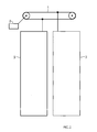
- the figure shows an inventive system of a drive belt 1, a drive unit 2 and two movable by means of the belt 1 elements 3, which are formed in the embodiment shown here as a door leaf.
- a learning run is first carried out in which the product of these variables is determined.
- the full opening width of the doors 3 is determined with an incremental encoder and also in both end positions the spring constant of the belt 1 by means of a measuring interval over which the belt 1 is stretched is, and the required power, which is obtained on the efficiency of the engine 2, measured.
- the controller moves the motor 2 in a short time over a small measuring interval and determines the force required for this purpose on the basis of the efficiency of the engine 2. It is important that the inertial mass of the belt 1 is significantly lower than that of the load 3, so that if possible, the belt 1 is stretched without causing the door 3 to move. Based on the measurement interval and the force required for the elongation and the product of modulus of elasticity and cross section of the drive belt 1 is now - as described above - the effective length of the belt 1 determined. Together with the knowledge of the end positions - which are known, for example, by the learning drive - this results in the positions of the door leaves 3, so that you know whether the doors are closed, open or only 10 cm open, for example.
- the inventive solution thus the elasticity property of a structurally necessary component is used in order to gain a position information of the load, without having to use additional sensors.
- the invention relates to a method for determining a position of at least one by means of a drive belt of a drive unit movable element.
- the invention further relates to a system of such components and a program for carrying out the method.
- a solution is proposed, wherein the drive belt is stretched over a measuring interval and a force required for this purpose over an efficiency the drive unit is determined, wherein from the measuring interval and the force and a modulus of elasticity and a cross section, an effective length of the drive belt is determined and wherein the position of the effective length is determined.
Landscapes
- Engineering & Computer Science (AREA)
- Automation & Control Theory (AREA)
- Physics & Mathematics (AREA)
- General Physics & Mathematics (AREA)
- Length Measuring Devices With Unspecified Measuring Means (AREA)
- Power-Operated Mechanisms For Wings (AREA)
- Control Of Position Or Direction (AREA)
- Control Or Security For Electrophotography (AREA)
- Discharging, Photosensitive Material Shape In Electrophotography (AREA)
- Devices For Conveying Motion By Means Of Endless Flexible Members (AREA)
Description
- Die Erfindung betrifft ein Verfahren zur Ermittlung einer Position zumindest eines mittels eines Antriebsriemens einer Antriebseinheit bewegbaren Elementes. Die Erfindung betrifft ferner ein System aus einer Antriebseinheit mit einer Steuerung, einem Antriebsriemen und einem bewegbaren Element; sie betrifft zudem ein Programm zum Ablauf in einer genannten Steuerung.
- Ein derartiges Verfahren, System und Programm kommt überall dort zum Einsatz, wo für die Ansteuerung der Antriebseinheit (wobei die Steuerung auch in die Antriebseinheit integriert sein kann), die Position des zu bewegenden Elementes - beispielsweise eine automatisch betätigte Tür - bekannt sein muss, da die Ansteuerung von Aktoren oftmals in Abhängigkeit der aktuellen Position (von eben z.B. einer motorisch betriebenen Aufzugstür) erfolgen muss.
- Kommt dann ein Inkrementalgeber zum Einsatz, so ist nach einem Spannungsausfall immer erst eine Initialisierungsfahrt erforderlich, um mindestens eine Endposition zu bestimmen. Typischerweise kommen hier Absolutwertgeber zum Einsatz, die die Position auch über mehrere Umdrehungen (Multiturn) eindeutig erfassen. Eine weitere Möglichkeit ist die Abstandsmessung per Ultraschall. Es sind aber auch Verfahren bekannt, die eine inkrementelle Erfassung auch bei Spannungsausfall weiterführen, so dass keine Inkremente verloren gehen.
- Weit verbreiteter Stand der Technik ist der Einsatz von Inkrementalgebern oder Hall-Gebern auf der Motorwelle des Antriebssystems. Hierbei wirkt sich der inkrementelle Ansatz als nachteilhaft aus, da hierbei immer von einer vorher bekannten Position aus "gerechnet" wird. Ferner ist der Encoder üblicherweise ein optischer Encoder, der nach Abschalten der Versorgungsspannung das Sensorsignal verliert. Bei Absolutgebern ist zwar nach neuem "Netz-Ein" eine Absolutposition des Rotorwinkels vorhanden, diese entspricht allerdings meist nicht der Position des bewegbaren Elementes, da zum Beispiel bei einer automatisch betätigten Tür bei einem Durchfahren der gesamten Türdistanz diese Absolutposition mehrfach vorhanden ist. Um dies zu umgehen, gibt es bisher prinzipiell mehrere Lösungen:
- 1. Versorgung des Sensors und der Auswerteelektronik für den Zeitbereich, in welchem die Stromversorgung unterbrochen ist. Dies kann, wenn ein langer Überbrückungszeitraum gewünscht ist, sehr aufwendig sein.
- 2. Mechanisch speicherndes System, z.B. über Zahnräder und ggf. mehrere Sensoren an den Achsen wird ein so genannter Multiturn-Encoder ausgebildet, der die gesamte mögliche - z.B. - Türstrecke als absolutes Sensorsignal abbildet.
- 3. Erfassung anhand eines Drahtseiles mit einem magnetostriktiven Messprinzip. Dieses ist üblicherweise bei der Erfassung der Fahrkorbposition (bei Auf- und Abwärtsfahrt) von Aufzügen eingesetzt.
- 4. Erfassung linearer Positionen anhand eines Codestreifens (optisch oder magnetisch o.ä.).
-
DE 10 2009 042 800 A offenbart ein Verfahren zur Ermittlung einer Position eines mittels eines Antriebsriemens einer Antriebseinheit bewegbaren Elementes, wobei ein Entfernungsmesser als Sensor eingesetzt wird. - Der Erfindung liegt die Aufgabe zugrunde, eine Absolutposition eines durch ein Antriebssystem bewegbaren Elementes in einer einfachen Art und Weise zu bestimmen.
- Diese Aufgabe wird gelöst durch ein Verfahren zur Ermittlung einer Position zumindest eines mittels eines Antriebsriemens einer Antriebseinheit bewegbaren Elementes, wobei der Antriebsriemen über ein Messintervall gedehnt wird und eine dafür benötigte Kraft über einen Wirkungsgrad der Antriebseinheit bestimmt wird, wobei aus dem Messintervall und der Kraft sowie einem Elastizitätsmodul und einem Querschnitt eine wirksame Länge des Antriebsriemens bestimmt wird und wobei aus der wirksamen Länge die Position bestimmt wird.
- Die Aufgabe wird weiter gelöst durch ein System und ein Programm mit den in Anspruch 5 bzw. 6 angegebenen Merkmalen.
- Die Bestimmung der Absolutposition des Antriebs (bzw. des bewegbaren Elementes) erfolgt mithilfe der Messung der Federkonstanten des Antriebsriemens, für die gilt:
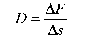
(Quotient aus Kraftänderung und Wegänderung). - Das Elastizitätsmodul des Riemens stellt eine Werkstoffkonstante dar und kann im Einsatzbereich normalerweise als konstant angesehen werden. Für den Zusammenhang von Elastizitätsmodul und Federkonstante gilt:

(Elastizitätsmodul multipliziert mit dem Querschnitt geteilt durch die Länge). - Damit ist die Kraft, die benötigt wird, den Riemen um einen bestimmten Weg zu spannen bzw. zu dehnen, umgekehrt proportional zur wirksamen Riemenlänge, die sich also wie folgt bestimmen lässt:

- Ein wesentlicher Punkt dabei ist, dass die Last (das bewegbare Element), die durch den Riemen angetrieben wird, sich nicht oder nur so wenig bewegt, dass es keinen Einfluss auf das Ergebnis hat, sofern man die Masse nicht kennt. Falls aber die Masse der Last bekannt ist, kann dieser Einfluss leicht herausgerechnet werden.
- Auch muss sich der Riemen soweit spannen lassen, dass sich eine messbare Strecke ergibt, und die träge Masse des Riemens muss sehr deutlich unter der der Last liegen. Und schließlich muss der Wirkungsgrad des Antriebs relativ gut bekannt oder vorhersagbar sein, damit man einen verlässlichen Wert für die wirksame Kraft bekommt.
- Aus der wirksamen Länge 1 ergibt sich die Absolutposition des bewegbaren Elementes entweder unmittelbar als Abstand zwischen Antriebseinheit und Last oder mittelbar durch einen Offset-Wert, der die konkrete Einbausituation berücksichtigt; im Falle einer Tür oder zweier Türflügel also beispielsweise "geschlossen", "20 cm offen" oder "offen" angibt, d.h. es kann z.B. bei einer kritischen Länge von 60 cm die Geschlossen-Position vorliegen.
- Diesen Wert sowie das Produkt aus Elastizitätsmodul und Querschnitt legt man vorteilhafterweise in einem nonvolatilen Speicher ab und kann künftig durch eine einmalige Messung direkt nach dem Einschalten (PowerOn) die Position der Last bestimmen.
- Mit der erfindungsgemäßen Lösung wird damit die sofortige Bestimmung der Position ermöglicht, wobei die bislang oft übliche Initialisierungsfahrt obsolet wird. Dabei wird die Elastizitätseigenschaft einer konstruktiv notwendigen Komponente genutzt, um hieraus eine Positionsinformation der Last zu gewinnen, ohne dafür zusätzliche Sensoren verwenden zu müssen.
- In einer vorteilhaften Form der Ausgestaltung wird der Antriebsriemen vorgespannt. In einer weiteren vorteilhaften Ausführungsform wird das bewegbare Element vor der Dehnung des Antriebsriemens auf eine gleichmäßige Geschwindigkeit gebracht. Dadurch, dass man die Last vorher auf eine kleine Geschwindigkeit bringt oder den Antriebsriemen vorspannt (falls man sich in einer Endposition befindet oder blockiert ist), kann die Messgenauigkeit gesteigert werden und vorteilhaft das Messintervall klein gehalten werden. Dadurch vermeidet man Fehler aufgrund von Spiel im Antriebsweg oder beschleunigten Bewegungen der Last.
- In einer weiteren vorteilhaften Ausführungsform wird ein Produkt aus Elastizitätsmodul und Querschnitt bei einer Lernfahrt bestimmt, bei der in zwei Positionen mit einem bekannten Abstand die für die Dehnung benötigte Kraft bestimmt wird. Hierdurch kann die erfindungsgemäße Lösung auch ohne vorherige Kenntnis des Elastizitätsmoduls oder Ausmessung des Querschnitts des Antriebsriemens durchgeführt werden, da für die Positionsbestimmung nur das genannte Produkt benötigt wird. Dieses ergibt sich - ausgedrückt durch die Federkonstanten D1 und D2 an den beiden Positionen x1 und x2 im Abstand x = x2 - x1, die sich aus den benötigten Kräften für die jeweiligen Messintervalle nach oben angegebener Formel ergeben - zu:

- Im realen Betrieb kann man den Vorgang weitgehend automatisieren. Dazu wird zunächst eine Lernfahrt im bislang üblichen Verfahren durchgeführt. Mit einem Inkrementalgeber erhält man dabei eine exakte Information über z.B. die volle Öffnungsweite. Zusätzlich führt man in beiden Endpositionen eine Messung der Federkonstanten durch. Man erhält damit zwei Werte für die Federkonstante, und mit Kenntnis des dazwischenliegenden Weges lässt sich über das Produkt EA die effektive (wirksame) Länge des Riemens bestimmen. Dabei sind gleichzeitig weitere Einflussfaktoren - wie z.B. der Wirkungsgrad des Motors - mit eingerechnet.
- Im Folgenden wird die Erfindung anhand des in der Figur dargestellten Ausführungsbeispiels näher beschrieben und erläutert. Die Figur zeigt:
- einen Türmechanismus als beispielhaftes System.
- Die Figur zeigt ein erfindungsgemäßes System aus einem Antriebsriemen 1, einer Antriebseinheit 2 und zwei mittels des Riemens 1 bewegbaren Elemente 3, die im hier gezeigten Ausführungsbeispiel als Türflügel ausgebildet sind. Um die Position der Türflügel 3 bei unbekanntem Elastizitätsmodul und Querschnitt des Antriebsriemens 1 bestimmen zu können, wird zunächst eine Lernfahrt durchgeführt, bei der das Produkt dieser Größen ermittelt wird. Hierzu wird die volle Öffnungsweite der Türen 3 mit einem Inkrementalgeber bestimmt und zudem in beiden Endpositionen die Federkonstante des Riemens 1 mittels eines Messintervalls, über das der Riemen 1 gedehnt wird, und der dafür benötigten Kraft, die man über den Wirkungsgrad des Motors 2 erhält, gemessen. Aus der Differenz der beiden Endpositionen - der Öffnungsweite - und den entsprechenden Federkonstanten kann dann das genannte Produkt berechnet werden, das vorteilhafterweise in einem nichtflüchtigen Speicher einer Steuerung des Motors 2 abgelegt wird, so dass danach durch eine einmalige Messung die Position der Türen 3 bestimmt werden kann.
- Zur eigentlichen Positionsbestimmung bewegt die Steuerung den Motor 2 in kurzer Zeit über ein kleines Messintervall und bestimmt die hierfür benötigte Kraft anhand des Wirkungsgrades des Motors 2. Wichtig dabei ist, dass die träge Masse des Riemens 1 deutlich unter der der Last 3 liegt, so dass möglichst der Riemen 1 gedehnt wird, ohne dass sich dabei die Türflügel 3 bewegen. Anhand des Messintervalls und der für die Dehnung benötigten Kraft sowie dem Produkt aus Elastizitätsmodul und Querschnitt des Antriebsriemens 1 wird nun - wie weiter oben beschrieben - die wirksame Länge des Riemens 1 bestimmt. Zusammen mit der Kenntnis über die Endpositionen - die beispielsweise durch die Lernfahrt bekannt sind - ergeben sich hieraus die Positionen der Türflügel 3, so dass man weiß, ob die Türen geschlossen, geöffnet oder nur beispielsweise 10 cm offen sind. Durch die erfindungsgemäße Lösung wird somit die Elastizitätseigenschaft einer konstruktiv notwendigen Komponente genutzt, um hieraus eine Positionsinformation der Last zu gewinnen, ohne dafür zusätzliche Sensoren verwenden zu müssen.
- Zusammenfassend betrifft die Erfindung ein Verfahren zur Ermittlung einer Position zumindest eines mittels eines Antriebsriemens einer Antriebseinheit bewegbaren Elementes. Die Erfindung betrifft ferner ein System aus derartigen Komponenten sowie ein Programm zur Durchführung des Verfahrens. Um eine Absolutposition des bewegbaren Elementes in einer einfachen Art und Weise zu bestimmen, wird eine Lösung vorgeschlagen, wobei der Antriebsriemen über ein Messintervall gedehnt wird und eine dafür benötigte Kraft über einen Wirkungsgrad der Antriebseinheit bestimmt wird, wobei aus dem Messintervall und der Kraft sowie einem Elastizitätsmodul und einem Querschnitt eine wirksame Länge des Antriebsriemens bestimmt wird und wobei aus der wirksamen Länge die Position bestimmt wird.
Claims (6)
- Verfahren zur Ermittlung einer Position zumindest eines mittels eines Antriebsriemens (1) einer Antriebseinheit (2) bewegbaren Elementes (3), wobei der Antriebsriemen (1) über ein Messintervall gedehnt wird und eine dafür benötigte Kraft über einen Wirkungsgrad der Antriebseinheit (2) bestimmt wird, wobei aus dem Messintervall und der Kraft sowie einem Elastizitätsmodul und einem Querschnitt eine wirksame Länge des Antriebsriemens (1) bestimmt wird und wobei aus der wirksamen Länge die Position bestimmt wird.
- Verfahren nach Anspruch 1,
wobei der Antriebsriemen (1) vorgespannt wird. - Verfahren nach Anspruch 1 oder 2,
wobei das bewegbare Element (3) vor der Dehnung des Antriebsriemens (1) auf eine gleichmäßige Geschwindigkeit gebracht wird. - Verfahren nach einem der vorhergehenden Ansprüche,
wobei ein Produkt aus Elastizitätsmodul und Querschnitt bei einer Lernfahrt bestimmt wird, bei der in zwei Positionen mit einem bekannten Abstand die für die Dehnung benötigte Kraft bestimmt wird. - System aus zumindest einer Antriebseinheit (2), einem Antriebsriemen (1) und einem mittels des Antriebsriemens (1) bewegbaren Element (3), wobei die Antriebseinheit (2) eine Steuerung mit Mitteln zur Durchführung eines Verfahrens nach einem der vorhergehenden Ansprüche aufweist.
- Programm zur Durchführung eines Verfahrens nach einem der Ansprüche 1 bis 4 bei Ablauf in einer Steuerung einer Antriebseinheit (2) in einem System nach Anspruch 5.
Applications Claiming Priority (2)
| Application Number | Priority Date | Filing Date | Title |
|---|---|---|---|
| DE102010056467 | 2010-12-30 | ||
| PCT/EP2011/073561 WO2012089580A1 (de) | 2010-12-30 | 2011-12-21 | Absolutpositionsbestimmung bei antriebssystemen |
Publications (2)
| Publication Number | Publication Date |
|---|---|
| EP2632841A1 EP2632841A1 (de) | 2013-09-04 |
| EP2632841B1 true EP2632841B1 (de) | 2014-12-17 |
Family
ID=45491547
Family Applications (1)
| Application Number | Title | Priority Date | Filing Date |
|---|---|---|---|
| EP11808628.9A Not-in-force EP2632841B1 (de) | 2010-12-30 | 2011-12-21 | Absolutpositionsbestimmung bei antriebssystemen |
Country Status (6)
| Country | Link |
|---|---|
| US (1) | US20130282327A1 (de) |
| EP (1) | EP2632841B1 (de) |
| CN (1) | CN103261080B (de) |
| DE (1) | DE102011003399B4 (de) |
| ES (1) | ES2529128T3 (de) |
| WO (1) | WO2012089580A1 (de) |
Families Citing this family (3)
| Publication number | Priority date | Publication date | Assignee | Title |
|---|---|---|---|---|
| DE102012204076B4 (de) * | 2012-03-15 | 2014-03-06 | Siemens Aktiengesellschaft | Positionsbestimmung mittels Winkelmessung |
| DE112014002813B4 (de) * | 2013-06-12 | 2021-05-06 | Mitsubishi Electric Corporation | Türeinrichtung und Türsteuerverfahren |
| CN104843571B (zh) * | 2015-04-14 | 2017-03-22 | 上海贝思特门机有限公司 | 自动识别门宽与门位置的电梯门机控制器 |
Family Cites Families (11)
| Publication number | Priority date | Publication date | Assignee | Title |
|---|---|---|---|---|
| ATE179387T1 (de) * | 1994-01-28 | 1999-05-15 | Inventio Ag | Verfahren zur steuerung der bewegung von türen |
| US6336656B1 (en) * | 1997-03-31 | 2002-01-08 | Simula, Inc. | Inflatable tubular torso restraint system with pivoting upper anchor point attachment |
| JP4140798B2 (ja) * | 1999-03-12 | 2008-08-27 | Ykk株式会社 | 自動ドアの駆動ユニット |
| US7140641B2 (en) * | 2001-02-06 | 2006-11-28 | Autoliv Development Ab | Safety-belt arrangement |
| WO2007028850A1 (en) * | 2005-09-05 | 2007-03-15 | Kone Corporation | Elevator arrangement |
| DE102006040232A1 (de) * | 2006-08-28 | 2008-03-13 | Siemens Ag | Türantrieb für eine automatische Tür |
| DE102006048851A1 (de) * | 2006-10-16 | 2008-04-17 | Siemens Ag | Vorrichtung und Verfahren zur Erfassung einer Position einer Antriebseinheit |
| DE202007016273U1 (de) * | 2007-11-20 | 2009-04-02 | Gebr. Bode Gmbh & Co. Kg | Antriebssystem für Ein- und Ausstiegseinrichtungen mit verbesserter Positionserfassung |
| JP2009127691A (ja) * | 2007-11-21 | 2009-06-11 | Bando Chem Ind Ltd | Vリブドベルト |
| ITMI20090097U1 (it) * | 2009-03-25 | 2010-09-26 | Imeas Spa | Dispositivo per controllare la posizione di un nastro abrasivo |
| DE102009042800A1 (de) * | 2009-09-25 | 2010-11-04 | Siemens Aktiengesellschaft | Nichtflüchtige Absolutpositionsbestimmung bei Antriebssystemen |
-
2011
- 2011-01-31 DE DE102011003399A patent/DE102011003399B4/de not_active Expired - Fee Related
- 2011-12-21 EP EP11808628.9A patent/EP2632841B1/de not_active Not-in-force
- 2011-12-21 US US13/977,771 patent/US20130282327A1/en not_active Abandoned
- 2011-12-21 ES ES11808628.9T patent/ES2529128T3/es active Active
- 2011-12-21 WO PCT/EP2011/073561 patent/WO2012089580A1/de not_active Ceased
- 2011-12-21 CN CN201180060010.9A patent/CN103261080B/zh not_active Expired - Fee Related
Also Published As
| Publication number | Publication date |
|---|---|
| DE102011003399B4 (de) | 2013-05-08 |
| CN103261080B (zh) | 2015-05-13 |
| US20130282327A1 (en) | 2013-10-24 |
| DE102011003399A1 (de) | 2012-07-05 |
| WO2012089580A1 (de) | 2012-07-05 |
| ES2529128T3 (es) | 2015-02-17 |
| EP2632841A1 (de) | 2013-09-04 |
| CN103261080A (zh) | 2013-08-21 |
Similar Documents
| Publication | Publication Date | Title |
|---|---|---|
| EP0919018B1 (de) | Verfahren zum berührungslosen anfahren der unteren anschlagsposition einer fremdkraftbetätigten fensterscheibe eines kraftfahrzeugs | |
| DE102011111450A1 (de) | Verfahren und Vorrichtung zur Überwachung eines einen rotierenden Antriebsmotor aufweisenden Antriebsaggregats, insbesondere eines Fensterhebers | |
| EP3757336B1 (de) | Verfahren zur bestimmung der spannung eines antriebsriemens | |
| DE102005039533A1 (de) | Verfahren für einen Torantrieb sowie ein Torantrieb zur Durchführung des Verfahrens | |
| WO2009053138A1 (de) | Verfahren und vorrichtung zur erhöhung der genauigkeit der positionsbestimmung eines motorgetriebenen schliessteiles eines fahrzeugs | |
| DE19718631A1 (de) | Verfahren zur Steuerung des Schließvorgangs von Schließvorrichtungen mit mindestens einem elektromotorisch bewegten Teil | |
| EP2659318B1 (de) | Verfahren und vorrichtung zum bereitstellen einer bewegungsangabe, insbesondere für eine blockiererkennung eines schliesssystems | |
| DE102009050185A1 (de) | Torantriebsvorrichtung mit Absolutwegsensor | |
| DE4315637A1 (de) | Verfahren zur Erkennung der Position, der Drehrichtung und/oder der Drehgeschwindigkeit eines drehbar gelagerten Teils | |
| EP2632841B1 (de) | Absolutpositionsbestimmung bei antriebssystemen | |
| DE102006062333A1 (de) | Türantrieb | |
| DE102013201448B4 (de) | Verfahren und Vorrichtung zum Betreiben einer elektrischen Fensterheberanlage, sowie eine Fensterhaberanlage und deren Verwendung in einer Fahrzeugtür | |
| EP4026753B1 (de) | Verfahren zur bestimmung des verschleisses eines lenksystems eines fahrzeugs | |
| DE19730196C2 (de) | Verfahren und Vorrichtung zur Füllstandsmessung nach dem Senklotprinzip | |
| DE102009042800A1 (de) | Nichtflüchtige Absolutpositionsbestimmung bei Antriebssystemen | |
| DE19919200A1 (de) | Verfahren zur Endlagenbestimmung von Toren sowie Torantrieb zur Durchführung des Verfahrens | |
| DE102011001884B3 (de) | Verfahren zum Steuern eines Türantriebs | |
| DE102008018628A1 (de) | Automatische Türanlage | |
| WO2007045596A1 (de) | Verfahren und steuereinrichtung zur automatischen bestimmung einer masse eines türsystems | |
| DE102012210592B4 (de) | Automatische Drehtüranlage sowie Verfahren zum Betrieb einer automatischen Drehtüranlage | |
| DE202007013225U1 (de) | Verstelleinrichtung | |
| EP2930297B1 (de) | Antriebsvorrichtung für ein Flächenelement | |
| WO2013135704A1 (de) | Positionsbestimmung mittels kraftmessung | |
| DE202005015869U1 (de) | Steuerungsvorrichtung einer Verstelleinrichtung eines Kraftfahrzeugs | |
| WO2013135715A1 (de) | Positionsbestimmung mittels winkelmessung |
Legal Events
| Date | Code | Title | Description |
|---|---|---|---|
| PUAI | Public reference made under article 153(3) epc to a published international application that has entered the european phase |
Free format text: ORIGINAL CODE: 0009012 |
|
| 17P | Request for examination filed |
Effective date: 20130527 |
|
| AK | Designated contracting states |
Kind code of ref document: A1 Designated state(s): AL AT BE BG CH CY CZ DE DK EE ES FI FR GB GR HR HU IE IS IT LI LT LU LV MC MK MT NL NO PL PT RO RS SE SI SK SM TR |
|
| DAX | Request for extension of the european patent (deleted) | ||
| GRAP | Despatch of communication of intention to grant a patent |
Free format text: ORIGINAL CODE: EPIDOSNIGR1 |
|
| RIC1 | Information provided on ipc code assigned before grant |
Ipc: B66B 13/14 20060101AFI20140627BHEP Ipc: E05F 15/14 20060101ALI20140627BHEP Ipc: G01B 5/14 20060101ALI20140627BHEP |
|
| INTG | Intention to grant announced |
Effective date: 20140715 |
|
| GRAS | Grant fee paid |
Free format text: ORIGINAL CODE: EPIDOSNIGR3 |
|
| GRAA | (expected) grant |
Free format text: ORIGINAL CODE: 0009210 |
|
| AK | Designated contracting states |
Kind code of ref document: B1 Designated state(s): AL AT BE BG CH CY CZ DE DK EE ES FI FR GB GR HR HU IE IS IT LI LT LU LV MC MK MT NL NO PL PT RO RS SE SI SK SM TR |
|
| REG | Reference to a national code |
Ref country code: GB Ref legal event code: FG4D Free format text: NOT ENGLISH Ref country code: DE Ref legal event code: R079 Ref document number: 502011005358 Country of ref document: DE Free format text: PREVIOUS MAIN CLASS: B66B0013140000 Ipc: G01B0005000000 |
|
| REG | Reference to a national code |
Ref country code: CH Ref legal event code: EP |
|
| REG | Reference to a national code |
Ref country code: IE Ref legal event code: FG4D Free format text: LANGUAGE OF EP DOCUMENT: GERMAN |
|
| REG | Reference to a national code |
Ref country code: AT Ref legal event code: REF Ref document number: 701725 Country of ref document: AT Kind code of ref document: T Effective date: 20150115 |
|
| REG | Reference to a national code |
Ref country code: DE Ref legal event code: R096 Ref document number: 502011005358 Country of ref document: DE Effective date: 20150129 Ref country code: DE Ref legal event code: R079 Ref document number: 502011005358 Country of ref document: DE Free format text: PREVIOUS MAIN CLASS: B66B0013140000 Ipc: G01B0005000000 Effective date: 20141217 |
|
| REG | Reference to a national code |
Ref country code: CH Ref legal event code: NV Representative=s name: SIEMENS SCHWEIZ AG, CH |
|
| REG | Reference to a national code |
Ref country code: ES Ref legal event code: FG2A Ref document number: 2529128 Country of ref document: ES Kind code of ref document: T3 Effective date: 20150217 |
|
| PG25 | Lapsed in a contracting state [announced via postgrant information from national office to epo] |
Ref country code: NO Free format text: LAPSE BECAUSE OF FAILURE TO SUBMIT A TRANSLATION OF THE DESCRIPTION OR TO PAY THE FEE WITHIN THE PRESCRIBED TIME-LIMIT Effective date: 20150317 Ref country code: FI Free format text: LAPSE BECAUSE OF FAILURE TO SUBMIT A TRANSLATION OF THE DESCRIPTION OR TO PAY THE FEE WITHIN THE PRESCRIBED TIME-LIMIT Effective date: 20141217 Ref country code: LT Free format text: LAPSE BECAUSE OF FAILURE TO SUBMIT A TRANSLATION OF THE DESCRIPTION OR TO PAY THE FEE WITHIN THE PRESCRIBED TIME-LIMIT Effective date: 20141217 |
|
| REG | Reference to a national code |
Ref country code: LT Ref legal event code: MG4D |
|
| PG25 | Lapsed in a contracting state [announced via postgrant information from national office to epo] |
Ref country code: SE Free format text: LAPSE BECAUSE OF FAILURE TO SUBMIT A TRANSLATION OF THE DESCRIPTION OR TO PAY THE FEE WITHIN THE PRESCRIBED TIME-LIMIT Effective date: 20141217 Ref country code: GR Free format text: LAPSE BECAUSE OF FAILURE TO SUBMIT A TRANSLATION OF THE DESCRIPTION OR TO PAY THE FEE WITHIN THE PRESCRIBED TIME-LIMIT Effective date: 20150318 Ref country code: LV Free format text: LAPSE BECAUSE OF FAILURE TO SUBMIT A TRANSLATION OF THE DESCRIPTION OR TO PAY THE FEE WITHIN THE PRESCRIBED TIME-LIMIT Effective date: 20141217 Ref country code: RS Free format text: LAPSE BECAUSE OF FAILURE TO SUBMIT A TRANSLATION OF THE DESCRIPTION OR TO PAY THE FEE WITHIN THE PRESCRIBED TIME-LIMIT Effective date: 20141217 Ref country code: HR Free format text: LAPSE BECAUSE OF FAILURE TO SUBMIT A TRANSLATION OF THE DESCRIPTION OR TO PAY THE FEE WITHIN THE PRESCRIBED TIME-LIMIT Effective date: 20141217 |
|
| PG25 | Lapsed in a contracting state [announced via postgrant information from national office to epo] |
Ref country code: BE Free format text: LAPSE BECAUSE OF NON-PAYMENT OF DUE FEES Effective date: 20141231 Ref country code: NL Free format text: LAPSE BECAUSE OF FAILURE TO SUBMIT A TRANSLATION OF THE DESCRIPTION OR TO PAY THE FEE WITHIN THE PRESCRIBED TIME-LIMIT Effective date: 20141217 |
|
| PG25 | Lapsed in a contracting state [announced via postgrant information from national office to epo] |
Ref country code: SK Free format text: LAPSE BECAUSE OF FAILURE TO SUBMIT A TRANSLATION OF THE DESCRIPTION OR TO PAY THE FEE WITHIN THE PRESCRIBED TIME-LIMIT Effective date: 20141217 Ref country code: EE Free format text: LAPSE BECAUSE OF FAILURE TO SUBMIT A TRANSLATION OF THE DESCRIPTION OR TO PAY THE FEE WITHIN THE PRESCRIBED TIME-LIMIT Effective date: 20141217 Ref country code: CZ Free format text: LAPSE BECAUSE OF FAILURE TO SUBMIT A TRANSLATION OF THE DESCRIPTION OR TO PAY THE FEE WITHIN THE PRESCRIBED TIME-LIMIT Effective date: 20141217 Ref country code: RO Free format text: LAPSE BECAUSE OF FAILURE TO SUBMIT A TRANSLATION OF THE DESCRIPTION OR TO PAY THE FEE WITHIN THE PRESCRIBED TIME-LIMIT Effective date: 20141217 |
|
| PG25 | Lapsed in a contracting state [announced via postgrant information from national office to epo] |
Ref country code: PL Free format text: LAPSE BECAUSE OF FAILURE TO SUBMIT A TRANSLATION OF THE DESCRIPTION OR TO PAY THE FEE WITHIN THE PRESCRIBED TIME-LIMIT Effective date: 20141217 Ref country code: IS Free format text: LAPSE BECAUSE OF FAILURE TO SUBMIT A TRANSLATION OF THE DESCRIPTION OR TO PAY THE FEE WITHIN THE PRESCRIBED TIME-LIMIT Effective date: 20150417 |
|
| REG | Reference to a national code |
Ref country code: DE Ref legal event code: R097 Ref document number: 502011005358 Country of ref document: DE |
|
| REG | Reference to a national code |
Ref country code: IE Ref legal event code: MM4A |
|
| PG25 | Lapsed in a contracting state [announced via postgrant information from national office to epo] |
Ref country code: MC Free format text: LAPSE BECAUSE OF FAILURE TO SUBMIT A TRANSLATION OF THE DESCRIPTION OR TO PAY THE FEE WITHIN THE PRESCRIBED TIME-LIMIT Effective date: 20141217 |
|
| PLBE | No opposition filed within time limit |
Free format text: ORIGINAL CODE: 0009261 |
|
| STAA | Information on the status of an ep patent application or granted ep patent |
Free format text: STATUS: NO OPPOSITION FILED WITHIN TIME LIMIT |
|
| PG25 | Lapsed in a contracting state [announced via postgrant information from national office to epo] |
Ref country code: DK Free format text: LAPSE BECAUSE OF FAILURE TO SUBMIT A TRANSLATION OF THE DESCRIPTION OR TO PAY THE FEE WITHIN THE PRESCRIBED TIME-LIMIT Effective date: 20141217 Ref country code: IE Free format text: LAPSE BECAUSE OF NON-PAYMENT OF DUE FEES Effective date: 20141221 |
|
| 26N | No opposition filed |
Effective date: 20150918 |
|
| REG | Reference to a national code |
Ref country code: FR Ref legal event code: PLFP Year of fee payment: 5 |
|
| PG25 | Lapsed in a contracting state [announced via postgrant information from national office to epo] |
Ref country code: SI Free format text: LAPSE BECAUSE OF FAILURE TO SUBMIT A TRANSLATION OF THE DESCRIPTION OR TO PAY THE FEE WITHIN THE PRESCRIBED TIME-LIMIT Effective date: 20141217 |
|
| PG25 | Lapsed in a contracting state [announced via postgrant information from national office to epo] |
Ref country code: SM Free format text: LAPSE BECAUSE OF FAILURE TO SUBMIT A TRANSLATION OF THE DESCRIPTION OR TO PAY THE FEE WITHIN THE PRESCRIBED TIME-LIMIT Effective date: 20141217 |
|
| PGFP | Annual fee paid to national office [announced via postgrant information from national office to epo] |
Ref country code: CH Payment date: 20160302 Year of fee payment: 5 |
|
| PG25 | Lapsed in a contracting state [announced via postgrant information from national office to epo] |
Ref country code: BG Free format text: LAPSE BECAUSE OF FAILURE TO SUBMIT A TRANSLATION OF THE DESCRIPTION OR TO PAY THE FEE WITHIN THE PRESCRIBED TIME-LIMIT Effective date: 20141217 Ref country code: CY Free format text: LAPSE BECAUSE OF FAILURE TO SUBMIT A TRANSLATION OF THE DESCRIPTION OR TO PAY THE FEE WITHIN THE PRESCRIBED TIME-LIMIT Effective date: 20141217 Ref country code: PT Free format text: LAPSE BECAUSE OF FAILURE TO SUBMIT A TRANSLATION OF THE DESCRIPTION OR TO PAY THE FEE WITHIN THE PRESCRIBED TIME-LIMIT Effective date: 20141217 |
|
| PG25 | Lapsed in a contracting state [announced via postgrant information from national office to epo] |
Ref country code: LU Free format text: LAPSE BECAUSE OF NON-PAYMENT OF DUE FEES Effective date: 20141221 Ref country code: MT Free format text: LAPSE BECAUSE OF FAILURE TO SUBMIT A TRANSLATION OF THE DESCRIPTION OR TO PAY THE FEE WITHIN THE PRESCRIBED TIME-LIMIT Effective date: 20141217 Ref country code: HU Free format text: LAPSE BECAUSE OF FAILURE TO SUBMIT A TRANSLATION OF THE DESCRIPTION OR TO PAY THE FEE WITHIN THE PRESCRIBED TIME-LIMIT; INVALID AB INITIO Effective date: 20111221 |
|
| REG | Reference to a national code |
Ref country code: FR Ref legal event code: PLFP Year of fee payment: 6 |
|
| PGFP | Annual fee paid to national office [announced via postgrant information from national office to epo] |
Ref country code: AT Payment date: 20161110 Year of fee payment: 6 |
|
| PGFP | Annual fee paid to national office [announced via postgrant information from national office to epo] |
Ref country code: TR Payment date: 20161128 Year of fee payment: 6 |
|
| REG | Reference to a national code |
Ref country code: CH Ref legal event code: PL |
|
| PG25 | Lapsed in a contracting state [announced via postgrant information from national office to epo] |
Ref country code: CH Free format text: LAPSE BECAUSE OF NON-PAYMENT OF DUE FEES Effective date: 20161231 Ref country code: LI Free format text: LAPSE BECAUSE OF NON-PAYMENT OF DUE FEES Effective date: 20161231 |
|
| REG | Reference to a national code |
Ref country code: FR Ref legal event code: PLFP Year of fee payment: 7 |
|
| PG25 | Lapsed in a contracting state [announced via postgrant information from national office to epo] |
Ref country code: MK Free format text: LAPSE BECAUSE OF FAILURE TO SUBMIT A TRANSLATION OF THE DESCRIPTION OR TO PAY THE FEE WITHIN THE PRESCRIBED TIME-LIMIT Effective date: 20141217 |
|
| REG | Reference to a national code |
Ref country code: AT Ref legal event code: MM01 Ref document number: 701725 Country of ref document: AT Kind code of ref document: T Effective date: 20171221 |
|
| PG25 | Lapsed in a contracting state [announced via postgrant information from national office to epo] |
Ref country code: AL Free format text: LAPSE BECAUSE OF FAILURE TO SUBMIT A TRANSLATION OF THE DESCRIPTION OR TO PAY THE FEE WITHIN THE PRESCRIBED TIME-LIMIT Effective date: 20141217 |
|
| PG25 | Lapsed in a contracting state [announced via postgrant information from national office to epo] |
Ref country code: AT Free format text: LAPSE BECAUSE OF NON-PAYMENT OF DUE FEES Effective date: 20171221 |
|
| PGFP | Annual fee paid to national office [announced via postgrant information from national office to epo] |
Ref country code: FR Payment date: 20181227 Year of fee payment: 8 Ref country code: GB Payment date: 20181212 Year of fee payment: 8 |
|
| PGFP | Annual fee paid to national office [announced via postgrant information from national office to epo] |
Ref country code: DE Payment date: 20190218 Year of fee payment: 8 Ref country code: IT Payment date: 20181220 Year of fee payment: 8 Ref country code: ES Payment date: 20190325 Year of fee payment: 8 |
|
| REG | Reference to a national code |
Ref country code: DE Ref legal event code: R119 Ref document number: 502011005358 Country of ref document: DE |
|
| GBPC | Gb: european patent ceased through non-payment of renewal fee |
Effective date: 20191221 |
|
| PG25 | Lapsed in a contracting state [announced via postgrant information from national office to epo] |
Ref country code: DE Free format text: LAPSE BECAUSE OF NON-PAYMENT OF DUE FEES Effective date: 20200701 Ref country code: GB Free format text: LAPSE BECAUSE OF NON-PAYMENT OF DUE FEES Effective date: 20191221 Ref country code: IT Free format text: LAPSE BECAUSE OF NON-PAYMENT OF DUE FEES Effective date: 20191221 Ref country code: FR Free format text: LAPSE BECAUSE OF NON-PAYMENT OF DUE FEES Effective date: 20191231 |
|
| REG | Reference to a national code |
Ref country code: ES Ref legal event code: FD2A Effective date: 20210525 |
|
| PG25 | Lapsed in a contracting state [announced via postgrant information from national office to epo] |
Ref country code: ES Free format text: LAPSE BECAUSE OF NON-PAYMENT OF DUE FEES Effective date: 20191222 |
|
| PG25 | Lapsed in a contracting state [announced via postgrant information from national office to epo] |
Ref country code: TR Free format text: LAPSE BECAUSE OF NON-PAYMENT OF DUE FEES Effective date: 20191221 |