EP2633210B1 - Dichtpackung zwischen zwei gegenüberliegenden elementen und um eine achse - Google Patents
Dichtpackung zwischen zwei gegenüberliegenden elementen und um eine achse Download PDFInfo
- Publication number
- EP2633210B1 EP2633210B1 EP11773472.3A EP11773472A EP2633210B1 EP 2633210 B1 EP2633210 B1 EP 2633210B1 EP 11773472 A EP11773472 A EP 11773472A EP 2633210 B1 EP2633210 B1 EP 2633210B1
- Authority
- EP
- European Patent Office
- Prior art keywords
- gland packing
- packing according
- envelope
- seal
- elements
- Prior art date
- Legal status (The legal status is an assumption and is not a legal conclusion. Google has not performed a legal analysis and makes no representation as to the accuracy of the status listed.)
- Not-in-force
Links
Images


Classifications
-
- F—MECHANICAL ENGINEERING; LIGHTING; HEATING; WEAPONS; BLASTING
- F16—ENGINEERING ELEMENTS AND UNITS; GENERAL MEASURES FOR PRODUCING AND MAINTAINING EFFECTIVE FUNCTIONING OF MACHINES OR INSTALLATIONS; THERMAL INSULATION IN GENERAL
- F16J—PISTONS; CYLINDERS; SEALINGS
- F16J15/00—Sealings
- F16J15/16—Sealings between relatively-moving surfaces
- F16J15/34—Sealings between relatively-moving surfaces with slip-ring pressed against a more or less radial face on one member
- F16J15/3436—Pressing means
- F16J15/3448—Pressing means the pressing force resulting from fluid pressure
-
- F—MECHANICAL ENGINEERING; LIGHTING; HEATING; WEAPONS; BLASTING
- F16—ENGINEERING ELEMENTS AND UNITS; GENERAL MEASURES FOR PRODUCING AND MAINTAINING EFFECTIVE FUNCTIONING OF MACHINES OR INSTALLATIONS; THERMAL INSULATION IN GENERAL
- F16J—PISTONS; CYLINDERS; SEALINGS
- F16J15/00—Sealings
- F16J15/16—Sealings between relatively-moving surfaces
- F16J15/34—Sealings between relatively-moving surfaces with slip-ring pressed against a more or less radial face on one member
-
- F—MECHANICAL ENGINEERING; LIGHTING; HEATING; WEAPONS; BLASTING
- F16—ENGINEERING ELEMENTS AND UNITS; GENERAL MEASURES FOR PRODUCING AND MAINTAINING EFFECTIVE FUNCTIONING OF MACHINES OR INSTALLATIONS; THERMAL INSULATION IN GENERAL
- F16J—PISTONS; CYLINDERS; SEALINGS
- F16J15/00—Sealings
- F16J15/16—Sealings between relatively-moving surfaces
- F16J15/34—Sealings between relatively-moving surfaces with slip-ring pressed against a more or less radial face on one member
- F16J15/3464—Mounting of the seal
- F16J15/3488—Split-rings
Definitions
- the subject of the invention is a packer disposed between two opposite elements and about an axis.
- Such gaskets comprise two blocks respectively connected to the opposite elements and in mutual contact by plane sliding faces, and a compression means arranged between one of the blocks and the corresponding element to exert and maintain a contact pressure between the faces. planes that maintains the seal.
- the opposite elements generally belong to a rotor and a stator and the flat surfaces, subjected to a mutual slip, then exert a dynamic seal.
- Other sealing means which are not part of the invention, are arranged between the elements and the blocks to complete the sealing statically.
- the invention relates to a seal of the aforementioned kind wherein the compression means is improved so that it exerts a uniform force over the entire circumference on which it is based even if it is shared between breakable blocks.
- the compression means can also be mounted around the axis by a substantially radial movement, such as breakable blocks, with which it shares the advantage of not requiring threading along. axis.
- the invention in a general form, relates to a seal disposed between two opposite elements and around an axis extending between the two elements, the lining comprising two blocks respectively connected to the elements and in mutual contact by planar faces. slidably, the blocks each being divided into portions extending over complementary circumferential sectors about the axis, and still a compression means disposed between one of the elements and one of the blocks and maintaining the contact of the sliding faces; the compression means is an inflatable seal housed in a groove of said element and comprising a flexible envelope comprising two closed and adjacent ends in the groove, and an inflation orifice.
- the seal is deflated and therefore soft on assembly, which allows to place it easily in the groove by wrapping around the axis and assembling its ends, then it is inflated and therefore transmits the compression necessary for the proper functioning of the garnish.
- the pressure being necessarily uniform in the envelope, portions of the blocks undergo an equal effort. The only possible inequality is at the junction of the ends of the envelope, but it is almost imperceptible.
- the envelope is tubular and the ends have flat faces and are united to extreme contours of the envelope.
- the ends may consist only of these flat faces or end pieces provided with tubular portions which extend the tube of the envelope.
- the section of the envelope is advantageously prismatic when inflated, the ends having an identical prismatic shape, and preferably substantially rectangular. A greater regularity of the effort is then obtained, the seal being perfectly supported in the groove on three sides and bearing on the block by a fourth face. The contact is tight, however, if the envelope has a bearing surface on the block which is provided with parallel teeth and extending from one end to the other.
- the orifice advantageously comprises a filling valve which maintains the seal at the desired pressure when it has been filled.
- This valve may be placed in a conduit of this element giving on the outside, or in a duct opening into a volume of fluid contained by the liner. In this latter design, it is the fluid itself that is retained by the lining that inflates the seal by its pressure.
- the fluid volume is divided by a flexible membrane into a main volume giving on the sliding faces and a subsidiary volume overlooking the duct: this is preferred when the fluid is pollutant, corrosive or loaded with impurities , to avoid clogging the inside of the seal or otherwise damaging it; a harmless fluid is poured into the annex volume and fills the joint, with a pressure that is still communicated to it by the main fluid to contain.
- the seal may contain a flexible stiffening element but non-deformable sections, which limits its crushing.
- FIG. figure 1 One end of a machine frame (1) is partially shown in FIG. figure 1 .
- the frame (1) surrounds a rotor shaft (2), the machine being circular about an axis (X).
- a housing (3) is assembled at the end of the frame (1) in a sealed manner and surrounds the shaft (2) with a small clearance.
- a seal (4) comprises a fixed block (5), a block mobile (6) and a seal (7) which constitutes the essential element of the invention.
- the blocks (5 and 6) are arranged in annular cavities of the frame (3) and a flange (8) of the shaft (2), which have opposite bottom faces (9 and 10). They are provided with dynamic sealing parts called "grains", respectively (11 and 12), which are integral with them and are in mutual contact by sliding faces (13).
- the block of the rotor (6) bears on the bottom face (10) of the flange (8), while the seal (7) bears on the bottom of the block (5) of the stator, pushing it towards the rotor block (6).
- the lining (4) closes the volume (14) delimited by the frame (1), the shaft (2) and the housing (3); sealing is provided by the seal (7), the contact between the sliding faces (13) and a gasket (15) disposed between the block of the rotor (6) and the shaft (2).
- a bore (16) which passes through the casing (3) is a degassing orifice closed by a suitable filter (17).
- the seal (7) has an inflation valve (25) which, in this design, passes through a duct (26) in the housing (3) and extends to the outside of the machine.
- the seal (7) is elastomeric, hollow, and can take a deflated and soft state where it is easy to introduce into the groove (18) and an inflated state in which it completely occupies this groove and overflows slightly to press on the block of the stator (5).
- the seal (7) is composed of a tube (27) of uniform section (referenced to figure 3 ) and two ends intended to close this tube, these ends being able to be platelets (28) flat ( figure 4 ) or still comprise an extension piece of the tube (29), of the same section as it, in addition to this plate (28) flat ( figure 5 ).
- the ends have the same section as the tube (27) and can be perfectly joined to it by vulcanization.
- the length of the tube (27) is such that the ends are adjacent when the seal (7) is placed in the groove (18).
- the inflation presses them against each other so as to make their junction tight. They can be constructed of a more flexible material than the tube (27) to better ensure this seal by continuous contact.
- the teeth (23) extend over the entire length of the seal (7), including at the ends.
- the figure 6 shows that the housing (3) is breakable and composed of two halves (3a and 3b) joined to each other by a joint line (3c), just like the blocks (5 and 6), as well as mentioned it.
- the junction (30) of the ends of the seal (7) is chosen at a distance from the seal line (3c) so as not to compromise the seal, which is not difficult since the valve (25) imposes the angular position of the seal. seal (7) in the groove (18).
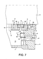
- FIG. 7 A slightly different design is represented at figure 7 : the conduit, here (31), in which the valve (25) extends into the volume (14) to be closed by the seal (4), so that the fluid contained in this volume itself ensures the inflation of the seal (7) entering the valve (25).
- Inflation can be either direct or exerted through a fluid pocket (34) formed around the outlet of the conduit (31) and defined by the housing (3) and a bell (32) comprising a portion deformable membrane (33), mounted sealingly on the housing (3) around the outlet of the conduit: it is then the fluid contained in the pocket (34) which fills the conduit (31) and the seal chamber (7). ) when it is installed.
- the sealing between the blocks (5 and 6) and the grains (11 and 12) is provided by elastic bracelets (35 and 36) compressed between them.
- Pins (37) hold the stator block (5) on the housing (3) with reduced angular movement.
- Other pins, not shown, connect the block of the rotor (6) to the flange (18).
- a stiffener (38) is placed in the joint (7) to limit its crushing during water hammers for example; it is flexible so as to be curved with the rest of the seal (7), but of indeformable section or little deformable.
Landscapes
- Engineering & Computer Science (AREA)
- General Engineering & Computer Science (AREA)
- Mechanical Engineering (AREA)
- Physics & Mathematics (AREA)
- Fluid Mechanics (AREA)
- Sealing Devices (AREA)
Claims (10)
- Dichtungspackung (4), angeordnet zwischen zwei sich gegenüberstehenden Elementen (3, 8) und um eine Achse (2) herum, die sich zwischen den beiden Elementen erstreckt, wobei die Packung zwei jeweils mit den Elementen verbundene und durch plane Gleitflächen (13) in gegenseitigem Kontakt befindliche Blöcke (5, 6), jeder unterteilt in sich über komplementäre Umfangssektoren um die Achse herum erstreckende Teilstücke, und außerdem eine Druckeinrichtung umfasst, die zwischen einem der Elemente und einem der Blöcke angeordnet ist und den Kontakt der Gleitflächen aufrecht erhält,
dadurch gekennzeichnet, dass die Druckeinrichtung eine aufblasbare Dichtung (7) ist, die in einer Nut des genannten Elements (3) sitzt und eine elastische Hülle (27) sowie eine Aufblasöffnung umfasst, und die elastische Hülle der Dichtung dabei zwei geschlossene und in der Nut aneinandergrenzende Enden umfasst. - Dichtungspackung nach Anspruch 1, dadurch gekennzeichnet, dass die Hülle (27) röhrenförmig ist, und die Enden ebene Flächen (28) haben und an Endkonturen der Hülle verbunden sind.
- Dichtungspackung nach Anspruch 2, dadurch gekennzeichnet, dass die Hülle einen prismatischen Querschnitt hat, wenn sie aufgeblasen ist, und die Enden eine identische prismatische Form haben.
- Dichtungspackung nach Anspruch 3, dadurch gekennzeichnet, dass der Querschnitt und die prismatische Form im Wesentlichen rechteckig sind.
- Dichtungspackung nach Anspruch 3, dadurch gekennzeichnet, dass die Hülle gegenüber dem Block eine Auflageseite hat, die parallele Zähne (23) aufweist und sich von einem der Enden zum anderen erstreckt.
- Dichtungspackung nach Anspruch 1, dadurch gekennzeichnet, dass die Öffnung ein Füllventil (25) umfasst.
- Dichtungspackung nach Anspruch 6, dadurch gekennzeichnet, dass das Ventil verbunden ist mit einer Leitung (31), die in einem in der Packung enthaltenen Fluidvolumen (14) mündet.
- Dichtungspackung nach Anspruch 7, dadurch gekennzeichnet, dass das Fluidvolumen durch eine nachgiebige Membran (33) unterteilt ist in ein mit den Gleitflächen verbundenes Hauptvolumen und ein mit der Leitung verbundenes Nebenvolumen.
- Dichtungspackung nach Anspruch 1, dadurch gekennzeichnet, dass die Dichtung eine nachgiebige Versteifung (38) umfasst.
- Dichtungspackung nach Anspruch 6, dadurch gekennzeichnet, dass das Ventil mit einer Leitung (26) verbunden ist, die zu einer Außenseite des Elements führt.
Applications Claiming Priority (2)
| Application Number | Priority Date | Filing Date | Title |
|---|---|---|---|
| FR1058824A FR2966898B1 (fr) | 2010-10-27 | 2010-10-27 | Garniture d'etancheite disposee entre deux elements opposes et autour d'un axe |
| PCT/EP2011/068597 WO2012055841A1 (fr) | 2010-10-27 | 2011-10-25 | Garniture d'etancheite disposee entre deux elements opposes et autour d'un axe |
Publications (2)
| Publication Number | Publication Date |
|---|---|
| EP2633210A1 EP2633210A1 (de) | 2013-09-04 |
| EP2633210B1 true EP2633210B1 (de) | 2014-10-22 |
Family
ID=44072620
Family Applications (1)
| Application Number | Title | Priority Date | Filing Date |
|---|---|---|---|
| EP11773472.3A Not-in-force EP2633210B1 (de) | 2010-10-27 | 2011-10-25 | Dichtpackung zwischen zwei gegenüberliegenden elementen und um eine achse |
Country Status (8)
| Country | Link |
|---|---|
| US (1) | US20130292910A1 (de) |
| EP (1) | EP2633210B1 (de) |
| CN (1) | CN103238013A (de) |
| BR (1) | BR112013010195A2 (de) |
| CA (1) | CA2815168A1 (de) |
| FR (1) | FR2966898B1 (de) |
| RU (1) | RU2013124053A (de) |
| WO (1) | WO2012055841A1 (de) |
Families Citing this family (4)
| Publication number | Priority date | Publication date | Assignee | Title |
|---|---|---|---|---|
| US20150197293A1 (en) * | 2014-01-14 | 2015-07-16 | Caterpillar Inc. | Track joint assemblies |
| FR3079903B1 (fr) | 2018-04-04 | 2022-12-23 | Commissariat Energie Atomique | Assemblage d'etancheite metallique pour l'etancheite entre un arbre tournant et un bati fixe |
| TWI742765B (zh) * | 2020-07-16 | 2021-10-11 | 龔祺允 | 充氣密封件 |
| CN118523530B (zh) * | 2024-05-16 | 2024-12-03 | 山西天地煤机装备有限公司 | 一种电机轴动密封装置 |
Family Cites Families (15)
| Publication number | Priority date | Publication date | Assignee | Title |
|---|---|---|---|---|
| GB1142329A (en) * | 1966-05-12 | 1969-02-05 | Us Metallic Packing Company Lt | Improvements in rotary shaft seals |
| US3491825A (en) * | 1968-01-18 | 1970-01-27 | Edwin F Peterson | Seal means for cooperative contacting surfaces in core boxes and the like |
| US3642291A (en) * | 1970-05-18 | 1972-02-15 | Goodrich Co B F | Inflatable seal |
| GB1345290A (en) * | 1971-12-23 | 1974-01-30 | Dunlop Ltd | Inflatable seals |
| US3810635A (en) * | 1972-03-20 | 1974-05-14 | Tec Group | Mechanical seal |
| FR2239159A5 (en) * | 1973-07-27 | 1975-02-21 | Cefilac | Inflatable shaft seal ring - forces non-turning disc against rotating seal to provide a seal |
| US3985365A (en) * | 1975-11-06 | 1976-10-12 | Bartholomew Thomas Catanzaro | Remotely actuated emergency shaft seal |
| EP0065646A1 (de) * | 1981-05-21 | 1982-12-01 | Dieter Kupka | Axiale Gleitringdichtung |
| DE3212939A1 (de) * | 1982-04-07 | 1983-11-10 | Dieter 6570 Kirn Kupka | Axiale gleitringdichtung |
| US5961122A (en) | 1995-07-21 | 1999-10-05 | Flowserve Management Company | Split mechanical face seal and method of assembly thereof |
| GB9704411D0 (en) * | 1997-03-04 | 1997-04-23 | Magna Interior Sys Ltd | Inflatable seals |
| DE19916789C1 (de) * | 1999-04-15 | 2000-09-21 | Fritsche, Moellmann Gmbh & Co Kg | Dichtvorrichtung |
| CN200999861Y (zh) * | 2006-11-12 | 2008-01-02 | 刘光新 | 软性充液孔腔复合密封圈 |
| CN201271568Y (zh) * | 2008-09-26 | 2009-07-15 | 江苏隆达机械设备有限公司 | 下搅拌密封装置 |
| CN101769378A (zh) * | 2009-01-04 | 2010-07-07 | 江苏华阳重工科技股份有限公司 | 船舶深海密封装置 |
-
2010
- 2010-10-27 FR FR1058824A patent/FR2966898B1/fr not_active Expired - Fee Related
-
2011
- 2011-10-25 EP EP11773472.3A patent/EP2633210B1/de not_active Not-in-force
- 2011-10-25 CN CN2011800520689A patent/CN103238013A/zh active Pending
- 2011-10-25 BR BR112013010195A patent/BR112013010195A2/pt not_active IP Right Cessation
- 2011-10-25 US US13/880,990 patent/US20130292910A1/en not_active Abandoned
- 2011-10-25 CA CA2815168A patent/CA2815168A1/fr not_active Abandoned
- 2011-10-25 WO PCT/EP2011/068597 patent/WO2012055841A1/fr not_active Ceased
- 2011-10-25 RU RU2013124053/06A patent/RU2013124053A/ru not_active Application Discontinuation
Also Published As
| Publication number | Publication date |
|---|---|
| CA2815168A1 (fr) | 2012-05-03 |
| WO2012055841A1 (fr) | 2012-05-03 |
| FR2966898B1 (fr) | 2013-08-23 |
| FR2966898A1 (fr) | 2012-05-04 |
| CN103238013A (zh) | 2013-08-07 |
| RU2013124053A (ru) | 2014-12-10 |
| BR112013010195A2 (pt) | 2019-09-24 |
| US20130292910A1 (en) | 2013-11-07 |
| EP2633210A1 (de) | 2013-09-04 |
Similar Documents
| Publication | Publication Date | Title |
|---|---|---|
| EP1961984B1 (de) | Lager für die Webtechnik mit einem Hohlraum zur Schmierung und einer Ziehvorrichtung für die Webtechnik mit solch einem Lager | |
| WO2012055841A1 (fr) | Garniture d'etancheite disposee entre deux elements opposes et autour d'un axe | |
| FR2623606A1 (fr) | Echangeur de chaleur comportant des chicanes presentant des joints d'etancheites | |
| FR2764038A1 (fr) | Cadre de moteur a turbine a gaz avec raccord de tuyauterie a profil plat | |
| WO2015011358A9 (fr) | Dispositif d'etancheite pour piston | |
| EP2412990B1 (de) | Gewindeverbindung und Verfahren zum Abdichten einer Gewindeverbindung | |
| EP1954461B1 (de) | Formwerkzeug für reifenlauffläche | |
| CA2738979C (fr) | Joint composite deformable pour portees a fort defaut de planeite | |
| EP3152472B1 (de) | Rotierender hochdruckdichtungsstopfen mit expandierbarem durchgehendem ring | |
| FR2775053A1 (fr) | Joint sans soudure | |
| FR2797021A1 (fr) | Lame d'etancheite dont le corps est divise en direction longitudinale | |
| CA1321573C (fr) | Garniture d'etancheite a anneau de reaction incorpore, notamment pour obturateur | |
| WO2008056743A1 (en) | O-ring-equipped metal packing for pipe joint | |
| FR2759139A1 (fr) | Vanne a coulisseau | |
| GB0720122D0 (en) | Sealing connectorand assembly consisting of a transmission member, a gas cartridge and an adapter comprising the connector | |
| FR2607898A1 (fr) | Suppresseur d'a-coups dans un circuit de fluide | |
| FR2909746A1 (fr) | Joint flexible a soufflet. | |
| FR2904075A1 (fr) | Support antivibratoire hydraulique, manchon interne pour un tel support et procede de fabrication d'un tel support. | |
| FR2660973A1 (fr) | Joint de culasse d'un compresseur alternatif. | |
| EP2299030A1 (de) | Vertikale Abschalvorrichtung für Gussmaterial zum Bauen | |
| EP1738932A1 (de) | Notlaufsystem mit einem wurstähnlichen Schaumstoff und verbesserten luftdichten Membranen | |
| FR2838487A1 (fr) | Soufflet d'etancheite et joint de transmission correspondant | |
| WO2013124546A1 (fr) | Robinet a papillon | |
| FR3068101A1 (fr) | Joint d'etancheite multicouche | |
| EP1426560B1 (de) | Dichtung für den Niederdruckverdichter eines Flugtriebwerks |
Legal Events
| Date | Code | Title | Description |
|---|---|---|---|
| PUAI | Public reference made under article 153(3) epc to a published international application that has entered the european phase |
Free format text: ORIGINAL CODE: 0009012 |
|
| 17P | Request for examination filed |
Effective date: 20130506 |
|
| AK | Designated contracting states |
Kind code of ref document: A1 Designated state(s): AL AT BE BG CH CY CZ DE DK EE ES FI FR GB GR HR HU IE IS IT LI LT LU LV MC MK MT NL NO PL PT RO RS SE SI SK SM TR |
|
| RIN1 | Information on inventor provided before grant (corrected) |
Inventor name: TOCHEPORT, GREGORY Inventor name: ROUCHOUZE, BRUNO Inventor name: JULIAA, JEAN-FRANCOIS Inventor name: DARQUE, JEAN-JACQUES Inventor name: LOMBARD, DAVID Inventor name: GUIMET, LAURENT Inventor name: GUIGNARD, STEPHANE |
|
| DAX | Request for extension of the european patent (deleted) | ||
| GRAP | Despatch of communication of intention to grant a patent |
Free format text: ORIGINAL CODE: EPIDOSNIGR1 |
|
| INTG | Intention to grant announced |
Effective date: 20140527 |
|
| GRAS | Grant fee paid |
Free format text: ORIGINAL CODE: EPIDOSNIGR3 |
|
| GRAA | (expected) grant |
Free format text: ORIGINAL CODE: 0009210 |
|
| AK | Designated contracting states |
Kind code of ref document: B1 Designated state(s): AL AT BE BG CH CY CZ DE DK EE ES FI FR GB GR HR HU IE IS IT LI LT LU LV MC MK MT NL NO PL PT RO RS SE SI SK SM TR |
|
| REG | Reference to a national code |
Ref country code: GB Ref legal event code: FG4D Free format text: NOT ENGLISH |
|
| REG | Reference to a national code |
Ref country code: CH Ref legal event code: EP |
|
| REG | Reference to a national code |
Ref country code: AT Ref legal event code: REF Ref document number: 692816 Country of ref document: AT Kind code of ref document: T Effective date: 20141115 |
|
| REG | Reference to a national code |
Ref country code: IE Ref legal event code: FG4D Free format text: LANGUAGE OF EP DOCUMENT: FRENCH |
|
| REG | Reference to a national code |
Ref country code: DE Ref legal event code: R096 Ref document number: 602011010820 Country of ref document: DE Effective date: 20141204 |
|
| REG | Reference to a national code |
Ref country code: NL Ref legal event code: VDEP Effective date: 20141022 |
|
| REG | Reference to a national code |
Ref country code: AT Ref legal event code: MK05 Ref document number: 692816 Country of ref document: AT Kind code of ref document: T Effective date: 20141022 |
|
| REG | Reference to a national code |
Ref country code: LT Ref legal event code: MG4D |
|
| PG25 | Lapsed in a contracting state [announced via postgrant information from national office to epo] |
Ref country code: LT Free format text: LAPSE BECAUSE OF FAILURE TO SUBMIT A TRANSLATION OF THE DESCRIPTION OR TO PAY THE FEE WITHIN THE PRESCRIBED TIME-LIMIT Effective date: 20141022 Ref country code: PT Free format text: LAPSE BECAUSE OF FAILURE TO SUBMIT A TRANSLATION OF THE DESCRIPTION OR TO PAY THE FEE WITHIN THE PRESCRIBED TIME-LIMIT Effective date: 20150223 Ref country code: NO Free format text: LAPSE BECAUSE OF FAILURE TO SUBMIT A TRANSLATION OF THE DESCRIPTION OR TO PAY THE FEE WITHIN THE PRESCRIBED TIME-LIMIT Effective date: 20150122 Ref country code: NL Free format text: LAPSE BECAUSE OF FAILURE TO SUBMIT A TRANSLATION OF THE DESCRIPTION OR TO PAY THE FEE WITHIN THE PRESCRIBED TIME-LIMIT Effective date: 20141022 Ref country code: IS Free format text: LAPSE BECAUSE OF FAILURE TO SUBMIT A TRANSLATION OF THE DESCRIPTION OR TO PAY THE FEE WITHIN THE PRESCRIBED TIME-LIMIT Effective date: 20150222 Ref country code: ES Free format text: LAPSE BECAUSE OF FAILURE TO SUBMIT A TRANSLATION OF THE DESCRIPTION OR TO PAY THE FEE WITHIN THE PRESCRIBED TIME-LIMIT Effective date: 20141022 Ref country code: FI Free format text: LAPSE BECAUSE OF FAILURE TO SUBMIT A TRANSLATION OF THE DESCRIPTION OR TO PAY THE FEE WITHIN THE PRESCRIBED TIME-LIMIT Effective date: 20141022 |
|
| REG | Reference to a national code |
Ref country code: DE Ref legal event code: R119 Ref document number: 602011010820 Country of ref document: DE |
|
| PG25 | Lapsed in a contracting state [announced via postgrant information from national office to epo] |
Ref country code: AT Free format text: LAPSE BECAUSE OF FAILURE TO SUBMIT A TRANSLATION OF THE DESCRIPTION OR TO PAY THE FEE WITHIN THE PRESCRIBED TIME-LIMIT Effective date: 20141022 Ref country code: PL Free format text: LAPSE BECAUSE OF FAILURE TO SUBMIT A TRANSLATION OF THE DESCRIPTION OR TO PAY THE FEE WITHIN THE PRESCRIBED TIME-LIMIT Effective date: 20141022 Ref country code: RS Free format text: LAPSE BECAUSE OF FAILURE TO SUBMIT A TRANSLATION OF THE DESCRIPTION OR TO PAY THE FEE WITHIN THE PRESCRIBED TIME-LIMIT Effective date: 20141022 Ref country code: GR Free format text: LAPSE BECAUSE OF FAILURE TO SUBMIT A TRANSLATION OF THE DESCRIPTION OR TO PAY THE FEE WITHIN THE PRESCRIBED TIME-LIMIT Effective date: 20150123 Ref country code: HR Free format text: LAPSE BECAUSE OF FAILURE TO SUBMIT A TRANSLATION OF THE DESCRIPTION OR TO PAY THE FEE WITHIN THE PRESCRIBED TIME-LIMIT Effective date: 20141022 Ref country code: SE Free format text: LAPSE BECAUSE OF FAILURE TO SUBMIT A TRANSLATION OF THE DESCRIPTION OR TO PAY THE FEE WITHIN THE PRESCRIBED TIME-LIMIT Effective date: 20141022 Ref country code: LV Free format text: LAPSE BECAUSE OF FAILURE TO SUBMIT A TRANSLATION OF THE DESCRIPTION OR TO PAY THE FEE WITHIN THE PRESCRIBED TIME-LIMIT Effective date: 20141022 Ref country code: CY Free format text: LAPSE BECAUSE OF FAILURE TO SUBMIT A TRANSLATION OF THE DESCRIPTION OR TO PAY THE FEE WITHIN THE PRESCRIBED TIME-LIMIT Effective date: 20141022 |
|
| REG | Reference to a national code |
Ref country code: CH Ref legal event code: PL |
|
| PG25 | Lapsed in a contracting state [announced via postgrant information from national office to epo] |
Ref country code: BE Free format text: LAPSE BECAUSE OF NON-PAYMENT OF DUE FEES Effective date: 20141031 |
|
| REG | Reference to a national code |
Ref country code: IE Ref legal event code: MM4A |
|
| PG25 | Lapsed in a contracting state [announced via postgrant information from national office to epo] |
Ref country code: CZ Free format text: LAPSE BECAUSE OF FAILURE TO SUBMIT A TRANSLATION OF THE DESCRIPTION OR TO PAY THE FEE WITHIN THE PRESCRIBED TIME-LIMIT Effective date: 20141022 Ref country code: RO Free format text: LAPSE BECAUSE OF FAILURE TO SUBMIT A TRANSLATION OF THE DESCRIPTION OR TO PAY THE FEE WITHIN THE PRESCRIBED TIME-LIMIT Effective date: 20141022 Ref country code: DE Free format text: LAPSE BECAUSE OF NON-PAYMENT OF DUE FEES Effective date: 20150501 Ref country code: LI Free format text: LAPSE BECAUSE OF NON-PAYMENT OF DUE FEES Effective date: 20141031 Ref country code: MC Free format text: LAPSE BECAUSE OF FAILURE TO SUBMIT A TRANSLATION OF THE DESCRIPTION OR TO PAY THE FEE WITHIN THE PRESCRIBED TIME-LIMIT Effective date: 20141022 Ref country code: DK Free format text: LAPSE BECAUSE OF FAILURE TO SUBMIT A TRANSLATION OF THE DESCRIPTION OR TO PAY THE FEE WITHIN THE PRESCRIBED TIME-LIMIT Effective date: 20141022 Ref country code: CH Free format text: LAPSE BECAUSE OF NON-PAYMENT OF DUE FEES Effective date: 20141031 Ref country code: SK Free format text: LAPSE BECAUSE OF FAILURE TO SUBMIT A TRANSLATION OF THE DESCRIPTION OR TO PAY THE FEE WITHIN THE PRESCRIBED TIME-LIMIT Effective date: 20141022 Ref country code: EE Free format text: LAPSE BECAUSE OF FAILURE TO SUBMIT A TRANSLATION OF THE DESCRIPTION OR TO PAY THE FEE WITHIN THE PRESCRIBED TIME-LIMIT Effective date: 20141022 |
|
| PLBE | No opposition filed within time limit |
Free format text: ORIGINAL CODE: 0009261 |
|
| STAA | Information on the status of an ep patent application or granted ep patent |
Free format text: STATUS: NO OPPOSITION FILED WITHIN TIME LIMIT |
|
| PG25 | Lapsed in a contracting state [announced via postgrant information from national office to epo] |
Ref country code: IT Free format text: LAPSE BECAUSE OF FAILURE TO SUBMIT A TRANSLATION OF THE DESCRIPTION OR TO PAY THE FEE WITHIN THE PRESCRIBED TIME-LIMIT Effective date: 20141022 |
|
| 26N | No opposition filed |
Effective date: 20150723 |
|
| PG25 | Lapsed in a contracting state [announced via postgrant information from national office to epo] |
Ref country code: IE Free format text: LAPSE BECAUSE OF NON-PAYMENT OF DUE FEES Effective date: 20141025 |
|
| REG | Reference to a national code |
Ref country code: FR Ref legal event code: PLFP Year of fee payment: 5 |
|
| PG25 | Lapsed in a contracting state [announced via postgrant information from national office to epo] |
Ref country code: SI Free format text: LAPSE BECAUSE OF FAILURE TO SUBMIT A TRANSLATION OF THE DESCRIPTION OR TO PAY THE FEE WITHIN THE PRESCRIBED TIME-LIMIT Effective date: 20141022 |
|
| PG25 | Lapsed in a contracting state [announced via postgrant information from national office to epo] |
Ref country code: SM Free format text: LAPSE BECAUSE OF FAILURE TO SUBMIT A TRANSLATION OF THE DESCRIPTION OR TO PAY THE FEE WITHIN THE PRESCRIBED TIME-LIMIT Effective date: 20141022 |
|
| GBPC | Gb: european patent ceased through non-payment of renewal fee |
Effective date: 20151025 |
|
| PG25 | Lapsed in a contracting state [announced via postgrant information from national office to epo] |
Ref country code: BG Free format text: LAPSE BECAUSE OF FAILURE TO SUBMIT A TRANSLATION OF THE DESCRIPTION OR TO PAY THE FEE WITHIN THE PRESCRIBED TIME-LIMIT Effective date: 20141022 |
|
| PG25 | Lapsed in a contracting state [announced via postgrant information from national office to epo] |
Ref country code: GB Free format text: LAPSE BECAUSE OF NON-PAYMENT OF DUE FEES Effective date: 20151025 Ref country code: LU Free format text: LAPSE BECAUSE OF NON-PAYMENT OF DUE FEES Effective date: 20141025 Ref country code: MT Free format text: LAPSE BECAUSE OF FAILURE TO SUBMIT A TRANSLATION OF THE DESCRIPTION OR TO PAY THE FEE WITHIN THE PRESCRIBED TIME-LIMIT Effective date: 20141022 Ref country code: HU Free format text: LAPSE BECAUSE OF FAILURE TO SUBMIT A TRANSLATION OF THE DESCRIPTION OR TO PAY THE FEE WITHIN THE PRESCRIBED TIME-LIMIT; INVALID AB INITIO Effective date: 20111025 Ref country code: TR Free format text: LAPSE BECAUSE OF FAILURE TO SUBMIT A TRANSLATION OF THE DESCRIPTION OR TO PAY THE FEE WITHIN THE PRESCRIBED TIME-LIMIT Effective date: 20141022 |
|
| REG | Reference to a national code |
Ref country code: FR Ref legal event code: PLFP Year of fee payment: 6 |
|
| REG | Reference to a national code |
Ref country code: FR Ref legal event code: PLFP Year of fee payment: 7 |
|
| PG25 | Lapsed in a contracting state [announced via postgrant information from national office to epo] |
Ref country code: MK Free format text: LAPSE BECAUSE OF FAILURE TO SUBMIT A TRANSLATION OF THE DESCRIPTION OR TO PAY THE FEE WITHIN THE PRESCRIBED TIME-LIMIT Effective date: 20141022 |
|
| REG | Reference to a national code |
Ref country code: FR Ref legal event code: PLFP Year of fee payment: 8 |
|
| PG25 | Lapsed in a contracting state [announced via postgrant information from national office to epo] |
Ref country code: AL Free format text: LAPSE BECAUSE OF FAILURE TO SUBMIT A TRANSLATION OF THE DESCRIPTION OR TO PAY THE FEE WITHIN THE PRESCRIBED TIME-LIMIT Effective date: 20141022 |
|
| PGFP | Annual fee paid to national office [announced via postgrant information from national office to epo] |
Ref country code: FR Payment date: 20221020 Year of fee payment: 12 |
|
| PG25 | Lapsed in a contracting state [announced via postgrant information from national office to epo] |
Ref country code: FR Free format text: LAPSE BECAUSE OF NON-PAYMENT OF DUE FEES Effective date: 20231031 |