EP2633218B1 - Rohrverbindung mit einem dichtring, der eine sperreinlage aufweist - Google Patents
Rohrverbindung mit einem dichtring, der eine sperreinlage aufweist Download PDFInfo
- Publication number
- EP2633218B1 EP2633218B1 EP11785749.0A EP11785749A EP2633218B1 EP 2633218 B1 EP2633218 B1 EP 2633218B1 EP 11785749 A EP11785749 A EP 11785749A EP 2633218 B1 EP2633218 B1 EP 2633218B1
- Authority
- EP
- European Patent Office
- Prior art keywords
- projection
- frontal
- assembly according
- socket
- spigot
- Prior art date
- Legal status (The legal status is an assumption and is not a legal conclusion. Google has not performed a legal analysis and makes no representation as to the accuracy of the status listed.)
- Active
Links
Images



Classifications
-
- F—MECHANICAL ENGINEERING; LIGHTING; HEATING; WEAPONS; BLASTING
- F16—ENGINEERING ELEMENTS AND UNITS; GENERAL MEASURES FOR PRODUCING AND MAINTAINING EFFECTIVE FUNCTIONING OF MACHINES OR INSTALLATIONS; THERMAL INSULATION IN GENERAL
- F16L—PIPES; JOINTS OR FITTINGS FOR PIPES; SUPPORTS FOR PIPES, CABLES OR PROTECTIVE TUBING; MEANS FOR THERMAL INSULATION IN GENERAL
- F16L37/00—Couplings of the quick-acting type
- F16L37/08—Couplings of the quick-acting type in which the connection between abutting or axially overlapping ends is maintained by locking members
- F16L37/084—Couplings of the quick-acting type in which the connection between abutting or axially overlapping ends is maintained by locking members combined with automatic locking
- F16L37/0845—Couplings of the quick-acting type in which the connection between abutting or axially overlapping ends is maintained by locking members combined with automatic locking by means of retaining members associated with the packing member
-
- F—MECHANICAL ENGINEERING; LIGHTING; HEATING; WEAPONS; BLASTING
- F16—ENGINEERING ELEMENTS AND UNITS; GENERAL MEASURES FOR PRODUCING AND MAINTAINING EFFECTIVE FUNCTIONING OF MACHINES OR INSTALLATIONS; THERMAL INSULATION IN GENERAL
- F16L—PIPES; JOINTS OR FITTINGS FOR PIPES; SUPPORTS FOR PIPES, CABLES OR PROTECTIVE TUBING; MEANS FOR THERMAL INSULATION IN GENERAL
- F16L37/00—Couplings of the quick-acting type
- F16L37/08—Couplings of the quick-acting type in which the connection between abutting or axially overlapping ends is maintained by locking members
- F16L37/084—Couplings of the quick-acting type in which the connection between abutting or axially overlapping ends is maintained by locking members combined with automatic locking
-
- F—MECHANICAL ENGINEERING; LIGHTING; HEATING; WEAPONS; BLASTING
- F16—ENGINEERING ELEMENTS AND UNITS; GENERAL MEASURES FOR PRODUCING AND MAINTAINING EFFECTIVE FUNCTIONING OF MACHINES OR INSTALLATIONS; THERMAL INSULATION IN GENERAL
- F16L—PIPES; JOINTS OR FITTINGS FOR PIPES; SUPPORTS FOR PIPES, CABLES OR PROTECTIVE TUBING; MEANS FOR THERMAL INSULATION IN GENERAL
- F16L21/00—Joints with sleeve or socket
- F16L21/02—Joints with sleeve or socket with elastic sealing rings between pipe and sleeve or between pipe and socket, e.g. with rolling or other prefabricated profiled rings
- F16L21/03—Joints with sleeve or socket with elastic sealing rings between pipe and sleeve or between pipe and socket, e.g. with rolling or other prefabricated profiled rings placed in the socket before connection
Definitions
- the document EP-A-526 373 discloses a composite seal comprising a sealing body and an anchoring heel of elastic material and a plurality of rigid material locking inserts embedded in the anchor heel.
- Each insert has an anchor head intended to bear on the bottom of an anchor groove formed in an interlocking end, as well as attachment teeth adapted to engage in the outer surface of a tip united so as to prevent axial movements that could separate the spigot from the socket end under the action of the axial forces generated by the pressure of the fluid flowing through the spigot end and the socket end.
- each locking insert is a function of the clearance between the outer diameter of the spigot and the internal diameter of the spigot end.
- the attachment of the insert on the spigot induces a reaction force whose angle of inclination on the median direction varies according to the game present between the assembled ends.
- the risk of having a poor resistance to pressure is critical towards the maximum clearances where the reaction angle is naturally low, while the risk of poor attachment of the inserts is critical towards the minimum clearances where this angle of reaction is naturally high.
- the position of the locking insert with respect to the spigot end and the socket end must be defined for any clearance allowed by manufacturing tolerances between the anchor groove and the spigot.
- the known locking junction limits the manufacturing tolerances on the inserts and the anchor groove of the interlocking end.
- the locking insert can take a configuration in which it is applied flat on the bottom surface of the anchor groove or on the inclined surface connecting the bottom surface and the front surface. . In the case where these surfaces have asperities, the orientation of the insert relative to the interlocking end is disturbed, leading to a poor locking of the junction. The removal of asperities, however, is expensive.
- An object of the invention is therefore to design a locking insert and a corresponding junction that allow a good grip on a wide range of games, while having a low manufacturing cost.
- Another object of the invention is to optimize the compromise between the hooking reliability of the insert on the spigot and the pressure resistance of the lock.
- the subject of the invention is an assembly as indicated above, the head comprising at least one frontal projection offset radially from the first inclined projection and adapted to bear against the annular front surface of the groove. anchoring, the annular front surface and the inclined surface forming an angle between them which is less than 180 °.
- the sealed assembly 2 comprises a plain end 4 or male end integral with a first pipe 6, an interlocking end 8 or female end integral with a second pipe 10, and a gasket 12.
- the assembly 2 extends along a central axis X-X.
- X-X central axis
- the seal 12 comprises, in meridian section, an elastic ring 14 made of flexible or resilient material, for example elastomer, which extends along the central axis XX, in which are embedded a plurality of locking inserts 20.
- the elastic ring 14 comprises an annular solid body 16 towards the bottom of the socket and, on the inlet side of the socket, an anchoring pin 18 projecting radially outwardly and a circular lip d sealing 26 projecting radially inwardly.
- the body 16 and the heel 18 are separated by a peripheral shoulder 22.
- the lip 26 extends substantially radially towards the axis XX to the vicinity of the minimum internal diameter of the body 16.
- the inserts 20 are evenly distributed around the periphery of the ring 14.
- Each locking insert 20 is made of high hardness, for example hard metal alloy or ceramic.
- Each insert 20 comprises, in meridian view, a radially outer head 30 and a radially inner foot 32.
- the head 30 extends substantially radially with respect to the axis XX, while the foot 32 is inclined with respect to this axis, so that it converges towards the axis XX in an insertion direction I of the spigot end 4 in the interlocking end 8.
- the insert 20 thus has a bent profile.
- Each insert 20 is partially embedded in the anchoring heel 18 of the lining 12 and partially covered by the elastic material of the heel 18.
- the heel 18 has recesses 36 to the right of the inserts 20.
- the recesses 36 are open radially towards the the outside, so that the radially outer end of the head 30 is almost free of elastic material.
- the recesses 36 are also axially open in the direction of introduction I.
- the seal 12 comprises recesses 38, open radially inward, and located at the location of the inserts 20, so that the radially inner end of the feet 32 is free of elastic material.
- the head 30 comprises at its radially outer end a profile constituting a radial projection 40.
- the head 30 further comprises a retaining nose 48 with a sharp edge directed axially in the direction I.
- the beak 48 is almost free of elastic material thanks to the recess 36.
- the head 30 further comprises an inclined projection 50 extending obliquely with respect to the central axis X-X.
- the two projections 40, 50 are formed by an arcuate profile of the locking insert, in meridian view.
- the head 30 further comprises a frontal projection 52 radially offset from the inclined projection 50 towards the X-X axis.
- a substantially planar surface S1 extends between the radial projection 40 and the retaining nose 48.
- a substantially planar surface S2 extends between the two inclined projections 50 and frontal 52. These surfaces S1, S2 form between them an angle ⁇ which is less than 90 °.
- the foot 32 comprises at its radially inner end three axially offset hooking teeth 56, 58, 60 which are adapted to catch on the outer surface 70 of the spigot end 4 (see below) and which, when the lining is in the state of rest, extend outside the elastic ring 14.
- the teeth 56, 58, 60 extend on a convex curve.
- the foot 32 comprises, on the axial side opposite to the head 30, an attachment stop 62 embedded in the body 16.
- the attachment stop 62 has, in meridian view, a profile which is rounded with respect to the profile gripping teeth 56, 58, 60.
- the stop 62 whose function is to limit the penetration of the insert 20 into the plain end 4 so as not to damage it, preferably has a rounded or curved shape to promote the "flow" of the elastomer during the casing of the spigot end 4, this so as to avoid stress concentrations that could cause tears in the elastomer.
- the plain end 4 comprises a cylindrical outer surface 70 of diameter d provided with a chamfer 72.
- the spigot 4 is made of diametral tolerances so that the actual diameter d may be located between a maximum outside diameter d max and a minimum outside diameter d min .
- the diameters d max and d min are indicated in phantom on the Figure 1 .
- the socket end 8 comprises successively, going axially from the inlet of the socket towards the bottom, an inlet collar 80, an annular anchoring groove 82 serving as a housing for the anchoring heel 18 of the liner, a stepped portion 84, an internal bead 86 and a receiving cavity 88, adapted to freely receive the end of the spigot end 4.
- the inlet collar 80 delimits an inlet surface 81, which is a cylindrical surface of diameter DISE (cf. Figure 4 ).
- the annular anchoring groove 82 is delimited by an annular front surface 90 of the inlet collar 80, by an inclined surface 91, by a cylindrical bottom surface 92 with a circular section of axis XX, as well as by a front surface 94 of the tiered portion 84.
- the front surface 90 extends at an angle of at least 80 ° with respect to the central axis XX and has an axial component directed in the direction I.
- the front surface 90 forms an angle d at least 85 ° with the axis XX.
- the front surface 90 extends from the entrance surface 81 to the inclined surface 91.
- the inclined surface 91 extends at an angle of between 30 ° and 60 ° relative to the central axis XX and has an axial component directed in the direction I.
- the inclined surface 91 is arranged radially and axially between the surface of the bottom 92 and the front surface 90.
- the annular front surface 90 is directly connected to the inclined surface 91, which connects directly to the bottom surface 92.
- the annular front surface 90 is connected to the inclined surface 91 at a connection point PR .
- This connection point PR is located at a distance DPRSE from the input surface 81, which distance is between 10% and 90% of the difference between the diameter of the input surface DISE and the diameter D of the surface of background 92.
- the distance DPRSE is between 40% and 60% of this difference or between 45% and 55% of this difference.
- the angle ⁇ included by the front surfaces 90 and inclined 91 is less than 180 ° and is in particular between 110 ° and 160 °.
- the insert 20 applies both on the one hand against the bottom surface 92 and secondly against the inclined surface 91, and / or against the front surface 90 when the pipes are subjected to the internal pressure of the fluid they carry.
- the locking insert 20 is applied against the bottom surface 92 and the inclined surface 91 when the pressure is established, but it does not apply against the front surface 90.
- the locking insert 20 When the clearance between the surfaces 70 and 92 is located in a second range of games, delimited by the maximum clearance J2 ( Fig. 6 and 7 ) and the intermediate play, the locking insert 20 is applied against the bottom surface 92 and the front surface 90 when the pressure is established, but not against the inclined surface 91. It should be noted in this case that, when of the pressurization and before reaching this final support configuration, the insert 20 passes first by a configuration in which it is applied against the bottom surface 92 and the inclined surface 91, and then by a configuration intermediate in which it is applied simultaneously against the bottom surface 92, the inclined surface 91 and the front surface 90.
- the front surface 94 is directed towards the inlet collar 80, against the direction I.
- the bottom surface 92 is also subject to manufacturing tolerances, so that its actual diameter D can vary between a maximum diameter D max and a minimum diameter D min .
- the maximum diameter d max of the surface 70 is smaller than the diameter DISE of the surface 81.
- the assembly of the assembly according to the invention is carried out as follows.
- the seal 12 is first introduced into the interlocking end 8, the body 16 pressing against the stepped portion 84 and the anchoring heel 18 taking place in the annular anchoring groove 82, such that so that the axis of the liner 12 is coincident with that of the interlocking end.
- the spigot 4 is aligned with the interlocking end and is introduced through the gasket 12 in the direction I by first folding the lip 26 which is applied with a certain pressure on the outer surface 70.
- the spigot 4 crosses the threshold of the inserts 20, they tilt by angular deflection against the body 16.
- the introduction of the spigot 4 is continued until its chamfer 72 comes close to the bottom of the cavity 88.
- the spigot end 4 is brought axially backwards so as to cause the inserts 20 to be turned back.
- the inserts 20 modify their inclination with respect to the X-X axis by a reverse angular deflection of the previous one and of small amplitude.
- at least one of the teeth 56, 58, 60 clings to the outer surface 70 of the spigot end 4 and then offers a substantial resistance to the continuation of the axial movement of withdrawal of the spigot 4. The locking of the assembly is thus achieved.
- each insert 20 takes a tilting position which varies as a function of the clearance present between the diameters d and D.
- the interlocking end 8 comprises an anchor groove 82 whose diameter D corresponds to the minimum diameter D min , while the spigot end 4 has a surface 70 whose outside diameter d corresponds to the maximum diameter d max.
- the two diameters D min and d max thus define a minimum clearance J1 between the two surfaces 92 and 70.
- the insert 20 is applied at two points against the groove 82, on the one hand with its radial projection 40 against the bottom surface 92 and on the other hand with its inclined protrusion 50 against the inclined surface 91.
- only the engagement tooth 56 closest to the interlocking inlet is applied against the outer surface 70 of the spigot.
- the insert 20 is inclined at a reaction angle which is defined as follows.
- the two lines L1, L2 which extend perpendicular to the surfaces 92, 91 at the respective projections 40, 50 of application of the insert 20 against the groove 82, intersect at a point P.
- the point application of the tooth 56 on the surface 70 defines with the point P a third line L3 serving to support the reaction force of the insert 20.
- the angle ⁇ 1 measured between this line L3 and a plane perpendicular to the XX axis is called "angle of reaction" to the snap.
- the attachment of the insert 20 is even better than this angle of reaction is weak. Due to the presence of the radial projection 40 and the inclined surface 91, the point P is in a position which is axially relatively close to the tooth 56, so that the angle ⁇ 1 is small for the given clearance J1, which promotes the attachment of the locking insert 20 on the surface 70.
- the locking insert 20 is applied with its radial projection 40 against the bottom surface 92 and with its protrusion 50 against the inclined surface 91.
- the point P is again the point of intersection of the lines L1, L2 of the normals to the surfaces 92, 91 at the projections 40, 50.
- the assembly defines a line L3, which extends between the point P and a point M located substantially mid-axial distance between the attachment teeth 56 and 60.
- the line L3 defines, with a plane perpendicular to the axis X-X, an angle of reaction ⁇ 2 under pressure established which is thus relatively large for the set clearance J1, which leads to a good pressure resistance of the locked assembly.
- the frontal projection 52 is out of contact with the front surface 90 both during the introduction of the spigot end 4 in the interlocking end 8 as during and after pressurization.
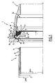
- the Figure 6 shows an assembly similar to that of the Figure 4 with the following differences.
- the surface 92 has a diameter D max , whereas the surface 70 has a diameter d min , so that these two surfaces define between them a clearance J2 which is greater than the clearance J1.
- This game J2 is the maximum allowable clearance for manufacturing tolerances of the spigot end 4 and the interlocking end 8.
- the insert 20 is applied at two points against the groove 82, on the one hand with its radial projection 40 against the surface of bottom 92 and on the other hand with its inclined projection 50 against the inclined surface 91.
- the frontal projection 52 is out of contact with the front surface 90.
- only the catching tooth 60 farthest from the interlocking entry is applied against the outer surface 70 of the spigot.
- the angle of reaction to the attachment ⁇ 3 obtained is measured between the radial direction and a line passing through the point P, substantially identical to that of the assembly of the Figure 5 , and by the point of contact between the surface 70 and the tooth 60. This angle ⁇ 3 is small and therefore compatible with good adhesion of the insert 20.
- the Figure 7 shows the assembly of the Figure 6 once the pressure is established, so after hooking of the insert 20 and after tilting thereof in the clockwise direction in the Figures.
- the insert 20 applies exclusively with its radial projection 40 against the bottom surface 92 and exclusively with its front projection 52 against the front surface 90, while the other projection 50 is out of contact with the surface 91.
- the intermediate tooth 58 and the tooth 60 farthest from the interlocking inlet cling into the surface 70 of the spigot 4.
- the insert 20 is applied, in meridian view, against the bottom surface 92, the inclined surface 91 and / or the front surface 90 at each contact location, according to a point and non-linear contact.
- the manufacturing tolerances of the insert and surfaces 90, 91, 92 can be important.
- the locking insert 20 has a rounded arcuate profile 100, which forms the projections 40 and 50. This rounded profile 100 extends over an angular range greater than 90 °.
- This profile 102 is connected in a tangential manner to the profile 100 and forms the surface S1.
- This profile 104 is connected tangentially to the profile 100 and forms the surface S2.
- the frontal projection 52 is formed by a rounded profile, preferably in an arc, extending over an angular range greater than 90 °.
- the frontal projection 52 and the attachment tooth 56 are connected by a concave profile 106.
- This concave profile 106 constitutes the clearance of the tooth 56 and comprises a straight partial profile 108 which extends from the front projection 52.
- the Figure 9 shows the middle game assembly.
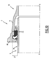
- the Figure 10 shows the assembly at maximum play J2.
- the locking insert 20 has a second inclined projection 54, radially offset from the first inclined projection 50. This inclined projection 54 is adapted to bear against the inclined surface 91 of the anchor groove.
- a rectilinear profile 104 extends between the frontal projection 52 and the second inclined projection 54 while the second inclined projection 54 and the first inclined projection 50 are separated by a concave profile 110.
- straight line which connects the two inclined projections 50, 54 forms with the rectilinear profile 104 an angle ⁇ which is different from the angle ⁇ between the two front surfaces 90 and inclined 91, and preferably less than this angle.
- the angle ⁇ is less than 180 °.
- the concave profile 110 helps to minimize the contact locations between the locking insert 20 and the inclined surface 91.
- the two inclined projections 50,54 are separated by a rectilinear profile.
- the frontal projection 52 and the inclined projection adjacent to the frontal projection which is the projection 54 on the Figure 11 , are connected by a concave profile.
- the seal leads to a good compromise between the attachment of the inserts on the spigot and the pressure resistance, regardless of the actual clearance between the surfaces 70 and 92.
- the recesses 36 make the support of the inserts 20 more reliable towards the minimum clearances, by reducing the casing engagement force of the spigot end 4 and by avoiding compression stresses in the elastomer that can cause incorrect positioning of the inserts. 20 by tilting in a direction tending to increase the angle of reaction (and thus to hinder the good adhesion of inserts 20 minimum clearance).
- the recesses 36 facilitate the overall deformation of the ring 14 during its introduction of the liner in the interlocking end.
Landscapes
- Engineering & Computer Science (AREA)
- General Engineering & Computer Science (AREA)
- Mechanical Engineering (AREA)
- Gasket Seals (AREA)
- Joints With Sleeves (AREA)
- Insertion Pins And Rivets (AREA)
Claims (11)
- Dichte und verriegelte Anordnung der Art, die ein Einsteckende (4) eines ersten Leitungselements und ein Aufsteckende (8) eines zweites Leitungselements und eine Kompositdichtung (12) für die dichte und verriegelte Anordnung zwischen dem Einsteckende (4) und dem Aufsteckende (8) umfasst, wobei die Dichtung zum einen einen Ring (14) aus elastischem Material, der sich gemäß einer Mittelachse (X-X) erstreckt und der einen Körper (16) und einen Verankerungsabsatz (18) hat, und zum anderen mindestens einen Verriegelungseinsatz (20), der zumindest teilweise in den Verankerungsabsatz (18) eingebettet ist, umfasst,
wobei das Aufsteckende eine ringförmige Verankerungsnut (82) umfasst, die von einer geneigten Fläche (91) begrenzt ist, die axial und radial zwischen einer Bodenfläche (92) und einer ringförmigen Stirnfläche (90) angeordnet ist,
wobei der Verriegelungseinsatz umfasst:- einen Kopf (30), der angepasst ist, in die Verankerungsnut (82) des Aufsteckelements eingefügt zu werden, und einen Fuß (32),wobei der Kopf (30) einen radialen Vorsprung (40), der angepasst ist, sich gegen die Bodenfläche (92) der Verankerungsnut (82) zu drücken, und einen ersten geneigten Vorsprung (50), der angepasst ist, sich gegen die geneigte Fläche (91) der Verankerungsnut (82) zu drücken, umfasst,
wobei der Kopf (30) mindestens einen Stirnvorsprung (52) umfasst, der radial zu dem ersten geneigten Vorsprung (50) versetzt ist, wobei die ringförmige Stirnfläche (90) und die geneigte Fläche (91) miteinander einen Winkel (γ) bilden, der kleiner als 180° ist, dadurch gekennzeichnet, dass der Stirnvorsprung (52) angepasst ist, sich gegen die ringförmige Stirnfläche (90) der Verankerungsnut (82) zu drücken. - Anordnung nach Anspruch 1, dadurch gekennzeichnet, dass der Kopf (30) mindestens einen zweiten geneigten Vorsprung (54) umfasst, der, insbesondere radial, zu dem ersten geneigten Vorsprung (50) und dem Stirnvorsprung (52) versetzt ist und angepasst ist, sich gegen die geneigte Fläche (91) der Verankerungsnut (82) zu drücken.
- Anordnung nach Anspruch 2, dadurch gekennzeichnet, dass der erste und der zweite geneigte Vorsprung (50, 54) gemäß einer Seitenansicht durch ein konkaves (110) oder geradliniges Profil verbunden sind.
- Anordnung nach einem beliebigen der vorhergehenden Ansprüche, dadurch gekennzeichnet, dass der Stirnvorsprung (52) und der zum Stirnvorsprung (52) benachbarte geneigte Vorsprung gemäß einer Seitenansicht durch ein konkaves oder geradliniges (104) Profil verbunden sind.
- Anordnung nach einem beliebigen der vorhergehenden Ansprüche, dadurch gekennzeichnet, dass von der Seite gesehen der Fuß (32) mindestens einen Eingreifzahn (56, 58, 60) umfasst, der angepasst ist, mit einer Außenfläche (70) des Einsteckendes (4) in Eingriff zu treten.
- Anordnung nach Anspruch 5, dadurch gekennzeichnet, dass der Stirnvorsprung (52) und der am nächsten liegende Eingreifzahn (56) gemäß einer Seitenansicht durch ein konkaves (106) oder geradliniges Profil verbunden sind.
- Anordnung nach einem beliebigen der vorhergehenden Ansprüche, dadurch gekennzeichnet, dass von der Seite gesehen der Kopf (30) einen Eingreifschnabel (48) aufweist, wobei eine erste gerade Linie sich von dem radialen Vorsprung (40) zu dem Eingreifschnabel erstreckt und eine zweite gerade Linie den Stirnvorsprung (52) mit dem ersten geneigten Vorsprung (50) verbindet und dass der Winkel (α) zwischen diesen zwei geraden Linien zwischen 60° und 120° liegt und vorzugsweise kleiner als 90° ist.
- Anordnung nach einem beliebigen der vorhergehenden Ansprüche, dadurch gekennzeichnet, dass der Kopf ein radial außenliegender Kopf (30) ist, der mindestens teilweise in den Verankerungsabsatz (18) eingebettet ist und vorgesehen ist, sich gegen die Verankerungsnut (82) des Aufsteckendes (8) zu drücken, und dass der Fuß ein radial innenliegender Fuß (32) ist, der vorgesehen ist, sich gegen das Einsteckende (4) zu drücken.
- Anordnung nach einem beliebigen der vorhergehenden Ansprüche, dadurch gekennzeichnet, dass die Stirnfläche (92), die die ringförmige Verankerungsnut (82) begrenzt, eine zylindrische Fläche ist, insbesondere sich koaxial zu der Mittelachse (X-X) erstreckt, und dass die ringförmige Stirnfläche (90) von einem Eintrittsbund (80) des Aufsteckendes (8) gebildet wird, wobei die ringförmige Stirnfläche (90) sich gemäß einem Winkel von mindestens 80° in Bezug auf die Mittelachse (X-X) erstreckt.
- Anordnung nach Anspruch 9, dadurch gekennzeichnet, dass die geneigte Fläche (91) eine Neigung zwischen 30° und 60° in Bezug auf die Mittelachse (X-X) aufweist.
- Anordnung nach Anspruch 10, dadurch gekennzeichnet, dass alle Vorsprünge (40, 50, 52) in der Weise angeordnet sind, dass für jeden Durchmesser der Stirnfläche (92) des Aufsteckendes und der Außenfläche (70) des Einsteckendes innerhalb eines Toleranzbereichs und gemäß einer Ansicht im Meridianschnitt der Verriegelungseinsatz (20) sich zugleich auf maximal drei oder zwei Stellen der Verankerungsnut (82) des Aufsteckendes abstützt.
Priority Applications (1)
| Application Number | Priority Date | Filing Date | Title |
|---|---|---|---|
| PL11785749T PL2633218T3 (pl) | 2010-10-26 | 2011-10-25 | Złącze z elementem uszczelniającym z wkładką blokującą |
Applications Claiming Priority (2)
| Application Number | Priority Date | Filing Date | Title |
|---|---|---|---|
| FR1058776A FR2966554B1 (fr) | 2010-10-26 | 2010-10-26 | Insert de verrouillage, garniture d'etancheite et assemblage correspondants |
| PCT/FR2011/052488 WO2012056163A1 (fr) | 2010-10-26 | 2011-10-25 | Assemblage avec garniture d'étanchéité à inserts de verrouillage. |
Publications (2)
| Publication Number | Publication Date |
|---|---|
| EP2633218A1 EP2633218A1 (de) | 2013-09-04 |
| EP2633218B1 true EP2633218B1 (de) | 2014-09-17 |
Family
ID=44358360
Family Applications (1)
| Application Number | Title | Priority Date | Filing Date |
|---|---|---|---|
| EP11785749.0A Active EP2633218B1 (de) | 2010-10-26 | 2011-10-25 | Rohrverbindung mit einem dichtring, der eine sperreinlage aufweist |
Country Status (11)
| Country | Link |
|---|---|
| US (1) | US20130229010A1 (de) |
| EP (1) | EP2633218B1 (de) |
| KR (1) | KR101894609B1 (de) |
| CN (1) | CN103282711B (de) |
| AU (1) | AU2011322332B2 (de) |
| BR (1) | BR112013010225B1 (de) |
| ES (1) | ES2523817T3 (de) |
| FR (1) | FR2966554B1 (de) |
| PL (1) | PL2633218T3 (de) |
| RU (1) | RU2577176C2 (de) |
| WO (1) | WO2012056163A1 (de) |
Families Citing this family (9)
| Publication number | Priority date | Publication date | Assignee | Title |
|---|---|---|---|---|
| US10088082B2 (en) * | 2013-05-17 | 2018-10-02 | Mcwane, Inc. | Pipe joint gasket and method of making same |
| CN105465362B (zh) * | 2014-09-09 | 2019-05-24 | 圣戈班管道系统有限公司 | 防脱密封圈,防脱块以及包括所述密封圈的管道组件 |
| US10107434B1 (en) * | 2015-10-02 | 2018-10-23 | Mcwane, Inc. | High deflection Restrained pipe joint |
| CN105240633B (zh) * | 2015-10-26 | 2016-11-09 | 新兴铸管股份有限公司 | 具有锚定结构的承插式管道接口 |
| US10400924B2 (en) * | 2015-12-24 | 2019-09-03 | American Cast Iron Pipe Company | Pipe joint with low insertion load, improved retention and increased high pressure sealing ability gasket and method of manufacture thereof |
| FR3110661B1 (fr) | 2020-05-20 | 2023-04-07 | Saint Gobain Pont A Mousson | Insert de verrouillage, garniture d’étanchéité et assemblage correspondants |
| CN112344108B (zh) * | 2020-11-27 | 2023-06-23 | 际华三五一七橡胶制品有限公司 | 一种具有预制保温层的球墨铸铁管 |
| FR3153122A1 (fr) * | 2023-09-14 | 2025-03-21 | Saint-Gobain Pam Canalisation | Dispositif de pose de tuyaux avec moyens de contrôle, ensemble et procédé correspondants |
| US12590660B1 (en) * | 2024-07-26 | 2026-03-31 | Mcwane, Llc | Reduced assembly force restraining gasket |
Family Cites Families (8)
| Publication number | Priority date | Publication date | Assignee | Title |
|---|---|---|---|---|
| US3962843A (en) * | 1970-04-30 | 1976-06-15 | King John O Jun | Resilient sleeve joint construction |
| US4643466A (en) * | 1984-03-29 | 1987-02-17 | American Cast Iron Pipe Company | Pipe joint assembly with snap ring and associated method |
| FR2679622B1 (fr) * | 1991-07-26 | 1994-09-30 | Pont A Mousson | Garniture d'etancheite composite pour assemblage verrouille de tuyaux, et assemblage verrouille correspondant. |
| FR2686140B1 (fr) * | 1992-01-13 | 1995-05-24 | Pont A Mousson | Joint a emboitement entre tuyaux et garniture d'etancheite pour un tel joint. |
| FR2708077B1 (fr) * | 1993-07-23 | 1995-09-22 | Pont A Mousson | Insert de verrouillage électriquement isolant pour garniture d'étanchéité, garniture d'étanchéité correspondante, et procédé de fabrication de tels inserts. |
| CN2388459Y (zh) * | 1999-08-02 | 2000-07-19 | 张胜 | 内螺纹压紧供排水管件 |
| US6688652B2 (en) * | 2001-12-12 | 2004-02-10 | U.S. Pipe And Foundry Company | Locking device and method for securing telescoped pipe |
| FR2875888B1 (fr) * | 2004-09-24 | 2006-12-01 | Saint Gobain Pam Sa | Garniture d'etancheite et assemblage correspondant |
-
2010
- 2010-10-26 FR FR1058776A patent/FR2966554B1/fr not_active Expired - Fee Related
-
2011
- 2011-10-25 EP EP11785749.0A patent/EP2633218B1/de active Active
- 2011-10-25 CN CN201180061998.0A patent/CN103282711B/zh active Active
- 2011-10-25 PL PL11785749T patent/PL2633218T3/pl unknown
- 2011-10-25 AU AU2011322332A patent/AU2011322332B2/en not_active Ceased
- 2011-10-25 US US13/881,348 patent/US20130229010A1/en not_active Abandoned
- 2011-10-25 ES ES11785749.0T patent/ES2523817T3/es active Active
- 2011-10-25 RU RU2013124052/06A patent/RU2577176C2/ru active
- 2011-10-25 WO PCT/FR2011/052488 patent/WO2012056163A1/fr not_active Ceased
- 2011-10-25 BR BR112013010225-0A patent/BR112013010225B1/pt active IP Right Grant
- 2011-10-25 KR KR1020137013253A patent/KR101894609B1/ko not_active Expired - Fee Related
Also Published As
| Publication number | Publication date |
|---|---|
| RU2013124052A (ru) | 2014-12-10 |
| AU2011322332B2 (en) | 2016-05-12 |
| US20130229010A1 (en) | 2013-09-05 |
| PL2633218T3 (pl) | 2015-03-31 |
| BR112013010225B1 (pt) | 2021-03-09 |
| CN103282711B (zh) | 2015-11-25 |
| BR112013010225A2 (pt) | 2020-09-01 |
| RU2577176C2 (ru) | 2016-03-10 |
| KR20140022771A (ko) | 2014-02-25 |
| KR101894609B1 (ko) | 2018-09-03 |
| FR2966554B1 (fr) | 2013-11-29 |
| EP2633218A1 (de) | 2013-09-04 |
| ES2523817T3 (es) | 2014-12-01 |
| FR2966554A1 (fr) | 2012-04-27 |
| WO2012056163A1 (fr) | 2012-05-03 |
| CN103282711A (zh) | 2013-09-04 |
| AU2011322332A1 (en) | 2013-05-23 |
Similar Documents
| Publication | Publication Date | Title |
|---|---|---|
| EP2633218B1 (de) | Rohrverbindung mit einem dichtring, der eine sperreinlage aufweist | |
| EP0893641B1 (de) | Vorrichtung zum Verbinden von zwei Rohrstücken und Anwendung der Verbindung von Rohrstücken | |
| EP1792110B1 (de) | Stopfbuchsendichtung und entsprechende anordnung | |
| EP0552123B1 (de) | Rohrsteckverbindung und deren Abdichtung | |
| EP2084446B1 (de) | Rohrverbindung | |
| EP1846687A1 (de) | Schnellkopplungsvorrichtung mit verriegelungs- und/oder lösemechanismus | |
| FR2942862A1 (fr) | Dispositif de raccordement pour transfert de fluide,circuit l'incorporant et son procede de montage/demontage. | |
| EP1780427B1 (de) | Nicht einschneidende Verankerungsscheibe | |
| FR2737275A1 (fr) | Raccord de tuyaux antiseparation | |
| EP2207988B1 (de) | Vorrichtung für eine griffrosette, griffrosette und entsprechender röhrenkonnektor | |
| CA2558028C (fr) | Dispositif d'immobilisation d'un anneau de retention axiale d'une aube, disque de rotor et anneau de retention associes, et rotor et moteur d'aeronef les comportant | |
| EP1860362B1 (de) | Rohrkupplung | |
| EP4153894B1 (de) | Abgedichtete und verriegelte anordnung | |
| EP2923132B1 (de) | Dichtungsanordnung für eine rohrverbindung und zugehörige rohrförmige verbindung | |
| EP1817520B1 (de) | Leicht in eine verbindungsbohrung einzuführende führungsbuchse und entsprechende verbindung | |
| EP2359045B1 (de) | Dichtungsanordnung und zugehörige rohrförmige verbindung | |
| EP4227566B1 (de) | Fluidanschlussbuchse und fluidkupplung mit einer solchen buchse | |
| FR3114624A1 (fr) | Ecrou a marqueur pour fixation de boulon et procede d’assemblage correspondant |
Legal Events
| Date | Code | Title | Description |
|---|---|---|---|
| PUAI | Public reference made under article 153(3) epc to a published international application that has entered the european phase |
Free format text: ORIGINAL CODE: 0009012 |
|
| 17P | Request for examination filed |
Effective date: 20130429 |
|
| AK | Designated contracting states |
Kind code of ref document: A1 Designated state(s): AL AT BE BG CH CY CZ DE DK EE ES FI FR GB GR HR HU IE IS IT LI LT LU LV MC MK MT NL NO PL PT RO RS SE SI SK SM TR |
|
| DAX | Request for extension of the european patent (deleted) | ||
| GRAP | Despatch of communication of intention to grant a patent |
Free format text: ORIGINAL CODE: EPIDOSNIGR1 |
|
| INTG | Intention to grant announced |
Effective date: 20140411 |
|
| GRAS | Grant fee paid |
Free format text: ORIGINAL CODE: EPIDOSNIGR3 |
|
| GRAA | (expected) grant |
Free format text: ORIGINAL CODE: 0009210 |
|
| AK | Designated contracting states |
Kind code of ref document: B1 Designated state(s): AL AT BE BG CH CY CZ DE DK EE ES FI FR GB GR HR HU IE IS IT LI LT LU LV MC MK MT NL NO PL PT RO RS SE SI SK SM TR |
|
| REG | Reference to a national code |
Ref country code: GB Ref legal event code: FG4D Free format text: NOT ENGLISH |
|
| REG | Reference to a national code |
Ref country code: CH Ref legal event code: EP |
|
| REG | Reference to a national code |
Ref country code: IE Ref legal event code: FG4D Free format text: LANGUAGE OF EP DOCUMENT: FRENCH |
|
| REG | Reference to a national code |
Ref country code: AT Ref legal event code: REF Ref document number: 687873 Country of ref document: AT Kind code of ref document: T Effective date: 20141015 |
|
| REG | Reference to a national code |
Ref country code: DE Ref legal event code: R096 Ref document number: 602011010008 Country of ref document: DE Effective date: 20141030 |
|
| REG | Reference to a national code |
Ref country code: CH Ref legal event code: NV Representative=s name: ARNOLD AND SIEDSMA AG, CH |
|
| REG | Reference to a national code |
Ref country code: ES Ref legal event code: FG2A Ref document number: 2523817 Country of ref document: ES Kind code of ref document: T3 Effective date: 20141201 |
|
| PG25 | Lapsed in a contracting state [announced via postgrant information from national office to epo] |
Ref country code: SE Free format text: LAPSE BECAUSE OF FAILURE TO SUBMIT A TRANSLATION OF THE DESCRIPTION OR TO PAY THE FEE WITHIN THE PRESCRIBED TIME-LIMIT Effective date: 20140917 Ref country code: LT Free format text: LAPSE BECAUSE OF FAILURE TO SUBMIT A TRANSLATION OF THE DESCRIPTION OR TO PAY THE FEE WITHIN THE PRESCRIBED TIME-LIMIT Effective date: 20140917 Ref country code: FI Free format text: LAPSE BECAUSE OF FAILURE TO SUBMIT A TRANSLATION OF THE DESCRIPTION OR TO PAY THE FEE WITHIN THE PRESCRIBED TIME-LIMIT Effective date: 20140917 Ref country code: GR Free format text: LAPSE BECAUSE OF FAILURE TO SUBMIT A TRANSLATION OF THE DESCRIPTION OR TO PAY THE FEE WITHIN THE PRESCRIBED TIME-LIMIT Effective date: 20141218 Ref country code: NO Free format text: LAPSE BECAUSE OF FAILURE TO SUBMIT A TRANSLATION OF THE DESCRIPTION OR TO PAY THE FEE WITHIN THE PRESCRIBED TIME-LIMIT Effective date: 20141217 |
|
| REG | Reference to a national code |
Ref country code: NL Ref legal event code: VDEP Effective date: 20140917 |
|
| REG | Reference to a national code |
Ref country code: LT Ref legal event code: MG4D |
|
| PG25 | Lapsed in a contracting state [announced via postgrant information from national office to epo] |
Ref country code: LV Free format text: LAPSE BECAUSE OF FAILURE TO SUBMIT A TRANSLATION OF THE DESCRIPTION OR TO PAY THE FEE WITHIN THE PRESCRIBED TIME-LIMIT Effective date: 20140917 Ref country code: HR Free format text: LAPSE BECAUSE OF FAILURE TO SUBMIT A TRANSLATION OF THE DESCRIPTION OR TO PAY THE FEE WITHIN THE PRESCRIBED TIME-LIMIT Effective date: 20140917 Ref country code: CY Free format text: LAPSE BECAUSE OF FAILURE TO SUBMIT A TRANSLATION OF THE DESCRIPTION OR TO PAY THE FEE WITHIN THE PRESCRIBED TIME-LIMIT Effective date: 20140917 Ref country code: RS Free format text: LAPSE BECAUSE OF FAILURE TO SUBMIT A TRANSLATION OF THE DESCRIPTION OR TO PAY THE FEE WITHIN THE PRESCRIBED TIME-LIMIT Effective date: 20140917 |
|
| PG25 | Lapsed in a contracting state [announced via postgrant information from national office to epo] |
Ref country code: NL Free format text: LAPSE BECAUSE OF FAILURE TO SUBMIT A TRANSLATION OF THE DESCRIPTION OR TO PAY THE FEE WITHIN THE PRESCRIBED TIME-LIMIT Effective date: 20140917 |
|
| REG | Reference to a national code |
Ref country code: PL Ref legal event code: T3 |
|
| PG25 | Lapsed in a contracting state [announced via postgrant information from national office to epo] |
Ref country code: SK Free format text: LAPSE BECAUSE OF FAILURE TO SUBMIT A TRANSLATION OF THE DESCRIPTION OR TO PAY THE FEE WITHIN THE PRESCRIBED TIME-LIMIT Effective date: 20140917 Ref country code: RO Free format text: LAPSE BECAUSE OF FAILURE TO SUBMIT A TRANSLATION OF THE DESCRIPTION OR TO PAY THE FEE WITHIN THE PRESCRIBED TIME-LIMIT Effective date: 20140917 Ref country code: IS Free format text: LAPSE BECAUSE OF FAILURE TO SUBMIT A TRANSLATION OF THE DESCRIPTION OR TO PAY THE FEE WITHIN THE PRESCRIBED TIME-LIMIT Effective date: 20150117 Ref country code: CZ Free format text: LAPSE BECAUSE OF FAILURE TO SUBMIT A TRANSLATION OF THE DESCRIPTION OR TO PAY THE FEE WITHIN THE PRESCRIBED TIME-LIMIT Effective date: 20140917 Ref country code: EE Free format text: LAPSE BECAUSE OF FAILURE TO SUBMIT A TRANSLATION OF THE DESCRIPTION OR TO PAY THE FEE WITHIN THE PRESCRIBED TIME-LIMIT Effective date: 20140917 Ref country code: PT Free format text: LAPSE BECAUSE OF FAILURE TO SUBMIT A TRANSLATION OF THE DESCRIPTION OR TO PAY THE FEE WITHIN THE PRESCRIBED TIME-LIMIT Effective date: 20150119 |
|
| REG | Reference to a national code |
Ref country code: DE Ref legal event code: R097 Ref document number: 602011010008 Country of ref document: DE |
|
| PG25 | Lapsed in a contracting state [announced via postgrant information from national office to epo] |
Ref country code: BE Free format text: LAPSE BECAUSE OF NON-PAYMENT OF DUE FEES Effective date: 20141031 Ref country code: MC Free format text: LAPSE BECAUSE OF FAILURE TO SUBMIT A TRANSLATION OF THE DESCRIPTION OR TO PAY THE FEE WITHIN THE PRESCRIBED TIME-LIMIT Effective date: 20140917 |
|
| PLBE | No opposition filed within time limit |
Free format text: ORIGINAL CODE: 0009261 |
|
| STAA | Information on the status of an ep patent application or granted ep patent |
Free format text: STATUS: NO OPPOSITION FILED WITHIN TIME LIMIT |
|
| REG | Reference to a national code |
Ref country code: IE Ref legal event code: MM4A |
|
| PG25 | Lapsed in a contracting state [announced via postgrant information from national office to epo] |
Ref country code: DK Free format text: LAPSE BECAUSE OF FAILURE TO SUBMIT A TRANSLATION OF THE DESCRIPTION OR TO PAY THE FEE WITHIN THE PRESCRIBED TIME-LIMIT Effective date: 20140917 |
|
| 26N | No opposition filed |
Effective date: 20150618 |
|
| REG | Reference to a national code |
Ref country code: FR Ref legal event code: PLFP Year of fee payment: 5 |
|
| PG25 | Lapsed in a contracting state [announced via postgrant information from national office to epo] |
Ref country code: IE Free format text: LAPSE BECAUSE OF NON-PAYMENT OF DUE FEES Effective date: 20141025 |
|
| PG25 | Lapsed in a contracting state [announced via postgrant information from national office to epo] |
Ref country code: SI Free format text: LAPSE BECAUSE OF FAILURE TO SUBMIT A TRANSLATION OF THE DESCRIPTION OR TO PAY THE FEE WITHIN THE PRESCRIBED TIME-LIMIT Effective date: 20140917 |
|
| PG25 | Lapsed in a contracting state [announced via postgrant information from national office to epo] |
Ref country code: SM Free format text: LAPSE BECAUSE OF FAILURE TO SUBMIT A TRANSLATION OF THE DESCRIPTION OR TO PAY THE FEE WITHIN THE PRESCRIBED TIME-LIMIT Effective date: 20140917 |
|
| PG25 | Lapsed in a contracting state [announced via postgrant information from national office to epo] |
Ref country code: BG Free format text: LAPSE BECAUSE OF FAILURE TO SUBMIT A TRANSLATION OF THE DESCRIPTION OR TO PAY THE FEE WITHIN THE PRESCRIBED TIME-LIMIT Effective date: 20140917 |
|
| PG25 | Lapsed in a contracting state [announced via postgrant information from national office to epo] |
Ref country code: HU Free format text: LAPSE BECAUSE OF FAILURE TO SUBMIT A TRANSLATION OF THE DESCRIPTION OR TO PAY THE FEE WITHIN THE PRESCRIBED TIME-LIMIT; INVALID AB INITIO Effective date: 20111025 Ref country code: MT Free format text: LAPSE BECAUSE OF FAILURE TO SUBMIT A TRANSLATION OF THE DESCRIPTION OR TO PAY THE FEE WITHIN THE PRESCRIBED TIME-LIMIT Effective date: 20140917 Ref country code: LU Free format text: LAPSE BECAUSE OF NON-PAYMENT OF DUE FEES Effective date: 20141025 |
|
| REG | Reference to a national code |
Ref country code: FR Ref legal event code: PLFP Year of fee payment: 6 |
|
| REG | Reference to a national code |
Ref country code: FR Ref legal event code: PLFP Year of fee payment: 7 |
|
| PG25 | Lapsed in a contracting state [announced via postgrant information from national office to epo] |
Ref country code: MK Free format text: LAPSE BECAUSE OF FAILURE TO SUBMIT A TRANSLATION OF THE DESCRIPTION OR TO PAY THE FEE WITHIN THE PRESCRIBED TIME-LIMIT Effective date: 20140917 |
|
| REG | Reference to a national code |
Ref country code: FR Ref legal event code: PLFP Year of fee payment: 8 |
|
| PG25 | Lapsed in a contracting state [announced via postgrant information from national office to epo] |
Ref country code: AL Free format text: LAPSE BECAUSE OF FAILURE TO SUBMIT A TRANSLATION OF THE DESCRIPTION OR TO PAY THE FEE WITHIN THE PRESCRIBED TIME-LIMIT Effective date: 20140917 |
|
| PGFP | Annual fee paid to national office [announced via postgrant information from national office to epo] |
Ref country code: CH Payment date: 20210928 Year of fee payment: 11 |
|
| PGFP | Annual fee paid to national office [announced via postgrant information from national office to epo] |
Ref country code: GB Payment date: 20210915 Year of fee payment: 11 |
|
| PGFP | Annual fee paid to national office [announced via postgrant information from national office to epo] |
Ref country code: DE Payment date: 20210914 Year of fee payment: 11 Ref country code: TR Payment date: 20211022 Year of fee payment: 11 Ref country code: AT Payment date: 20210928 Year of fee payment: 11 |
|
| PGFP | Annual fee paid to national office [announced via postgrant information from national office to epo] |
Ref country code: PL Payment date: 20211006 Year of fee payment: 11 |
|
| REG | Reference to a national code |
Ref country code: DE Ref legal event code: R119 Ref document number: 602011010008 Country of ref document: DE |
|
| REG | Reference to a national code |
Ref country code: CH Ref legal event code: PL |
|
| REG | Reference to a national code |
Ref country code: AT Ref legal event code: MM01 Ref document number: 687873 Country of ref document: AT Kind code of ref document: T Effective date: 20221025 |
|
| GBPC | Gb: european patent ceased through non-payment of renewal fee |
Effective date: 20221025 |
|
| PG25 | Lapsed in a contracting state [announced via postgrant information from national office to epo] |
Ref country code: LI Free format text: LAPSE BECAUSE OF NON-PAYMENT OF DUE FEES Effective date: 20221031 Ref country code: DE Free format text: LAPSE BECAUSE OF NON-PAYMENT OF DUE FEES Effective date: 20230503 Ref country code: CH Free format text: LAPSE BECAUSE OF NON-PAYMENT OF DUE FEES Effective date: 20221031 Ref country code: AT Free format text: LAPSE BECAUSE OF NON-PAYMENT OF DUE FEES Effective date: 20221025 |
|
| PG25 | Lapsed in a contracting state [announced via postgrant information from national office to epo] |
Ref country code: GB Free format text: LAPSE BECAUSE OF NON-PAYMENT OF DUE FEES Effective date: 20221025 |
|
| PG25 | Lapsed in a contracting state [announced via postgrant information from national office to epo] |
Ref country code: PL Free format text: LAPSE BECAUSE OF NON-PAYMENT OF DUE FEES Effective date: 20221025 |
|
| PGFP | Annual fee paid to national office [announced via postgrant information from national office to epo] |
Ref country code: IT Payment date: 20251126 Year of fee payment: 15 |
|
| PGFP | Annual fee paid to national office [announced via postgrant information from national office to epo] |
Ref country code: FR Payment date: 20251205 Year of fee payment: 15 |
|
| PGFP | Annual fee paid to national office [announced via postgrant information from national office to epo] |
Ref country code: ES Payment date: 20251230 Year of fee payment: 15 |