EP2633585B1 - Passive sicherheitsvorrichtung und internes kurzschlussgeprüftes verfahren für energiespeicherzellen und systeme - Google Patents
Passive sicherheitsvorrichtung und internes kurzschlussgeprüftes verfahren für energiespeicherzellen und systeme Download PDFInfo
- Publication number
- EP2633585B1 EP2633585B1 EP10859069.6A EP10859069A EP2633585B1 EP 2633585 B1 EP2633585 B1 EP 2633585B1 EP 10859069 A EP10859069 A EP 10859069A EP 2633585 B1 EP2633585 B1 EP 2633585B1
- Authority
- EP
- European Patent Office
- Prior art keywords
- electrically conductive
- energy storage
- storage cell
- separator
- conductive layer
- Prior art date
- Legal status (The legal status is an assumption and is not a legal conclusion. Google has not performed a legal analysis and makes no representation as to the accuracy of the status listed.)
- Active
Links
Images





Classifications
-
- H—ELECTRICITY
- H01—ELECTRIC ELEMENTS
- H01M—PROCESSES OR MEANS, e.g. BATTERIES, FOR THE DIRECT CONVERSION OF CHEMICAL ENERGY INTO ELECTRICAL ENERGY
- H01M10/00—Secondary cells; Manufacture thereof
- H01M10/42—Methods or arrangements for servicing or maintenance of secondary cells or secondary half-cells
- H01M10/4235—Safety or regulating additives or arrangements in electrodes, separators or electrolyte
-
- H—ELECTRICITY
- H01—ELECTRIC ELEMENTS
- H01M—PROCESSES OR MEANS, e.g. BATTERIES, FOR THE DIRECT CONVERSION OF CHEMICAL ENERGY INTO ELECTRICAL ENERGY
- H01M10/00—Secondary cells; Manufacture thereof
- H01M10/42—Methods or arrangements for servicing or maintenance of secondary cells or secondary half-cells
- H01M10/4285—Testing apparatus
-
- H—ELECTRICITY
- H01—ELECTRIC ELEMENTS
- H01M—PROCESSES OR MEANS, e.g. BATTERIES, FOR THE DIRECT CONVERSION OF CHEMICAL ENERGY INTO ELECTRICAL ENERGY
- H01M10/00—Secondary cells; Manufacture thereof
- H01M10/42—Methods or arrangements for servicing or maintenance of secondary cells or secondary half-cells
- H01M10/48—Accumulators combined with arrangements for measuring, testing or indicating the condition of cells, e.g. the level or density of the electrolyte
-
- H—ELECTRICITY
- H01—ELECTRIC ELEMENTS
- H01M—PROCESSES OR MEANS, e.g. BATTERIES, FOR THE DIRECT CONVERSION OF CHEMICAL ENERGY INTO ELECTRICAL ENERGY
- H01M50/00—Constructional details or processes of manufacture of the non-active parts of electrochemical cells other than fuel cells, e.g. hybrid cells
- H01M50/50—Current conducting connections for cells or batteries
- H01M50/572—Means for preventing undesired use or discharge
- H01M50/574—Devices or arrangements for the interruption of current
- H01M50/581—Devices or arrangements for the interruption of current in response to temperature
-
- H—ELECTRICITY
- H01—ELECTRIC ELEMENTS
- H01M—PROCESSES OR MEANS, e.g. BATTERIES, FOR THE DIRECT CONVERSION OF CHEMICAL ENERGY INTO ELECTRICAL ENERGY
- H01M2200/00—Safety devices for primary or secondary batteries
-
- H—ELECTRICITY
- H01—ELECTRIC ELEMENTS
- H01M—PROCESSES OR MEANS, e.g. BATTERIES, FOR THE DIRECT CONVERSION OF CHEMICAL ENERGY INTO ELECTRICAL ENERGY
- H01M2200/00—Safety devices for primary or secondary batteries
- H01M2200/10—Temperature sensitive devices
-
- H—ELECTRICITY
- H01—ELECTRIC ELEMENTS
- H01M—PROCESSES OR MEANS, e.g. BATTERIES, FOR THE DIRECT CONVERSION OF CHEMICAL ENERGY INTO ELECTRICAL ENERGY
- H01M2200/00—Safety devices for primary or secondary batteries
- H01M2200/10—Temperature sensitive devices
- H01M2200/103—Fuse
-
- Y—GENERAL TAGGING OF NEW TECHNOLOGICAL DEVELOPMENTS; GENERAL TAGGING OF CROSS-SECTIONAL TECHNOLOGIES SPANNING OVER SEVERAL SECTIONS OF THE IPC; TECHNICAL SUBJECTS COVERED BY FORMER USPC CROSS-REFERENCE ART COLLECTIONS [XRACs] AND DIGESTS
- Y02—TECHNOLOGIES OR APPLICATIONS FOR MITIGATION OR ADAPTATION AGAINST CLIMATE CHANGE
- Y02E—REDUCTION OF GREENHOUSE GAS [GHG] EMISSIONS, RELATED TO ENERGY GENERATION, TRANSMISSION OR DISTRIBUTION
- Y02E60/00—Enabling technologies; Technologies with a potential or indirect contribution to GHG emissions mitigation
- Y02E60/10—Energy storage using batteries
Definitions
- the described subject matter relates to a passive safety device and a safety test method for energy storage devices.
- Energy storage cells also referred to herein as “cells” or “batteries” sold for consumer use in portable electronic devices and other applications have occasional failure in the field. These cells have typically passed a wide variety of safety tests, such as those required by governmental shipping regulations and by other certification organizations, but fail after the cells have been in use over time (e.g., several months), even though there have been no other reported problems with the cells that fail. Regardless, these failures can result in the cells overheating, and in some cases, going into thermal runaway wherein the cell can ignite and burn. For example, these incidents have been reported in the media as "the burning laptop” and have resulted in the recall of millions of batteries.
- a passive safety device (also referred to herein as "switch”) is disclosed for an energy storage cell for positioning between two electrically conductive layers of the energy storage cell.
- the device comprises a separator and a non-conductive layer.
- a first electrically conductive material is provided on the non-conductive layer.
- a first opening is formed through the separator between the first electrically conductive material and one of the electrically conductive layers of the energy storage cell.
- a second electrically conductive material is provided adjacent the first electrically conductive material on the non-conductive layer, wherein a space is formed on the non-conductive layer between the first and second electrically conductive materials.
- a second opening is formed through the non-conductive layer between the second electrically conductive material and another of the electrically conductive layers of the energy storage cell.
- the first and second electrically conductive materials combine and exit at least partially through the first and second openings to connect the two electrically conductive layers of the energy storage cell at a predetermined temperature.
- a method of generating an electrical short between two electrically conductive layers of the energy storage cell comprises: providing a first electrically conductive material on a non-conductive layer; forming a first opening through a separator between the first electrically conductive material and one of the electrically conductive layers of the energy storage cell; providing a second electrically conductive material adjacent the first electrically conductive material on the non-conductive layer, wherein a space is formed on the non-conductive layer between the first and second electrically conductive materials; forming a second opening through the non-conductive layer between the second electrically conductive material and another of the electrically conductive layers of the energy storage cell; and combining the first and second electrically conductive materials to exit at least partially through the first and second openings to connect the two electrically conductive layers of the energy storage cell at a predetermined temperature.
- the device or switch is used in a test method to simulate latent flaws for triggering internal short circuit in energy storage cells.
- the device is implanted in a cell in a specific and user-defined location between specific and user-defined internal layers of the cell.
- the cell is formed, or charged and discharged, or aged according to user-defined specifications.
- the device is activated by the appropriate stimulus such as heating, sonication, radiation, etc. in a test facility. After activation, the device creates a conductive path between the positive and negative layers of the cell. The response of the cell will be measured as the results of this internal short circuit.
- embodiments are disclosed herein which include a switch inside the battery itself, which is activated by an increase in temperature or other external mechanisms such as sonication or radiation.
- exemplary embodiments may be utilized with spirally-wound and stacked flat-plate cells containing any of the common lithium-ion, lithium sulfur, or lithium air electrochemical components.
- the switch may be placed anywhere within the battery and may be used, for example, with both spirally wound and flat-plate cells in either cylindrical or prismatic configurations. The switch activates automatically when a predetermined temperature or condition is reached.
- the switch includes a material which melts at a predetermined temperature (or range of temperatures) and causes the positive and negative components (electrodes, current collectors, and or foils) of the battery to be electrically connected.
- the switch may also include an electrically conductive material or combination of materials.
- the perimeter of the switch may be attached to the battery separator material by thermal/chemical bonding (e.g., "glued” or otherwise attached) or mechanical bonding.
- Exemplary positioning of the switch includes but is not limited to: 1) between the cathode and anode, 2) between the cathode and the negative electrode, 3) between the anode and the positive electrode, and 4) between the positive and negative electrodes.
- Each of these configurations represents different types of internal shorts. Placement of the switch on different areas of the separator enables different shorting mechanisms. Upon activation of the switch, the cathode and anode of the battery are electrically connected which results in an internal short.
- the battery can be operated (including cycled through charges) as it normally would as long as the temperature does not meet or exceed the activation temperature of the switch.
- the switch activates (e.g., either due to an artificial or "test-facility-generated” increase in temperature (and other stress factors) or an actual increase in temperature during use)
- the cathode and anode of the battery are electrically connected to produce an internal short in the battery. Accordingly, the switch may be used at test facilities to produce an on-demand failure.
- the switch has application in batteries that are distributed for normal use as a passive safety device which activates automatically when a predetermined temperature (or condition) is reached, and shorts the battery, and safely dissipates its energy, before it gets hot enough to ignite and cause a fire.
- the switch may be positioned anywhere within the battery and may be used with both spirally wound and flat-plate cells.
- the switch placed in the battery only activates if a predetermined temperature or condition is achieved. Therefore, the battery can be used and cycled as long as the switch temperature does not exceed the switch's activation temperature. Once the switch is activated, the cathode and anode of the battery are electrically connected and an internal short results.
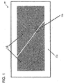
- Figure 1 shows the switch 10 as it may be positioned within an electrochemical cell.
- the switch includes a non-conductive material 12, such as a piece of separator material already used within the battery.
- the length and width may be as short as about 0.010 inches or as long as several inches.
- An electrically conductive material 14 is placed on the separator material.
- a partial list of how an electrically conductive material 14 can be deposited are through chemical vapor deposition, plasma enhanced chemical vapor deposition, physical vapor deposition, thermal evaporator, electron beam evaporator, sputtering, and plating.
- a sheet of electrically conductive material 14 can also be cut to the desired shape and placed, melted, or glued onto the non conductive material.
- the electrically conductive material 14 may have a melting point between about 10°C and 150°C and have a thickness of less than 500 microns.
- the switch 10 includes at least two portions of electrically conductive material that are separated by a small space 16, sized between about 0.0005 and 0.25 inches.
- FIG. 2 shows how the switch 10 may be placed in a battery.
- the perimeter of the switch 10 is attached to the battery separator material 18 through thermal bonding 19 or is "glued" to the separator material 18.
- Most separator materials 18 are poor wicks when it comes to liquefied metal. Therefore, a small hole or slit 20a may be formed through the battery separator material 18 adjacent one of the electrically conductive areas, and a second small hole or slit 20b may be formed through the non-conductive material 12 adjacent the second electrically conductive area.
- the size of the hole or slit 20a-b defines how much current flows through the internal short once the short is activated. For example, if the hole or slit 20a-b is large, then a hard short will exist in the battery. If the hole or slit 20a-b is small, then a "soft" short will exist within the battery. Furthermore, the amount of current drawn through the switch 10 can be adjusted by adjusting the distance between the two holes 20a-b and the cross sectional area of the electrically conductive material 14.
- Figure 3 shows how current is shunted through the switch 10 from the cathode to the anode (both sides shown by reference 24, as either side can be the cathode or the anode) by the current path indicated by arrows 22.
- the electrically conductive material 14 and the battery are brought up to the melting point of the conductive material 14. Once the melting point is achieved, the two sides of the switch 10 flow together making contact between the cathode and anode of the battery. Thus, allowing current to flow within the battery and mimicking an internal short.
- the electrically conductive material 14 is an indium alloy. But any material may be used having the desired melting point (e.g., below 150°C) and is electrically conductive.
- the switch can come in a number of different configurations.
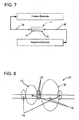
- Figures 4-7 show exemplary configurations of the switch.
- a material melts and causes the positive and negative electrodes of an energy storage device to be electrically connected.
- the electrically conductive material in the switch can be a combination of materials that have high and low melting points.
- Figure 8 shows another exemplary design of the switch 10 when using an electrically conductive material 14 with a low melting point. This design helps ensure that when the electrically conductive material 14 melts, no matter the direction of the flow of material 14, a short will be created between the two sides of the battery.
- the switch can be applied or used in any of a wide variety of different configurations.
- Figures 9a-d and Figures 10a -e are illustrative of several exemplary configurations of the switch 10.
- at least one material 14 combines (e.g., by melting) an d causes the positive and negative electrodes of the energy storage device to be electrically connected.
- the electrically conductive material can be a combination of materials, e.g., having different melting points.
- a phase change material (PCM) or wax design for the switch 10 is also contemplated for internally shorting an energy storage device, and exemplary embodiments are illustrated in Figures 11a -e.
- the PCM or wax is used as an insulator preventing the cathode and anode from making contact during normal operation of the battery. Once the battery is brought up in temperature to the melting point of the PCM or wax, the wax, having a very low viscosity, is wicked away by the battery separator and a short is created between the cathode and anode of the energy storage device.
- This design offers compact configuration for the switch 10, obviates conducting current through a low melting point alloy, and has demonstrated consistent repeatability in shorting coin cells.
- Figure 12 illustrates exemplary placement of the switch 10 in a battery 11, wherein the switch 10 is shown a) between the cathode and anode active material coatings, b) between the cathode and the current collector of the negative electrode, c) between the anode and the current collector of the positive electrode, and d) between the positive and negative electrode current collectors. It is noted that these configurations are shown for purposes of illustration only, and are not intended to be limiting. Configuring the switch on different areas of the separator enables different shorting mechanisms and conditions.
- the internal short may be used as a passive safety device within the cell to prevent the cell from going into thermal runaway.
- the batteries are typically prevented from going into thermal runaway by the battery management system (BMS).
- BMS battery management system
- a BMS is any electronic device that manages a rechargeable battery by monitoring state, calculating data, reporting data, and so forth.
- the BMS itself may fail.
- the BMS may not monitor the temperature of every battery in the battery pack, and an unmonitored battery may increase in temperature without the BMS detecting and issuing a warning signal to the vehicle engineering control unit (ECU) which monitors electronic and mechanical systems for the vehicle.
- ECU vehicle engineering control unit
- a battery can heat up, for example, due to one or more of the following reasons (or other reasons not set forth herein):
- the separator in battery systems allows ionic conduction between the cathode and anode, but electrically isolates the cathode and anode from each other.
- the separator shrinks as it heats up. If, for example, the temperature of a battery increases due to an over-voltage situation, the separator keeps the cathode and anode apart until the separator reaches approximately 120°C to 150°C. After the separator begins to shrink, however, the cathode and anode are no longer isolated from each other and a violent exothermic chemical reaction may ensue.
- the melting point of the switch can be selected so that the cell shorts in a controlled manner through a predetermined resistance.
- the switch comprises an electrically conductive material that has a low melting point and a thin/thick film resistor that is attached to the non-conductive patch by the use of a solder (low or high temperature solders can be used).
- a solder low or high temperature solders can be used.
- One side of the switch is connected to the anode and the other side of the switch is connected to the cathode.
- the melting point of the low melting point or phase change material is selected so that the switch is activated before the separator shrinks, but high enough to prevent nuisance activations from normal operations.
- the low-melting point material or PCM melts, it connects the anode or negative side of the cell to the cathode or positive side of the cell through the resistor.
- the impedance/resistance of the resistor can be selected such that a known current travels through the resistor.
- the safety device may be located near the wall of the battery such that the heat developed during discharge can be dissipated to ambient air or other cooling devices.
- the energy in the battery may be dissipated through the switch, thereby pre venting the separator from failing, and preventing or reducing the occurrence of a violent reaction.
- the switch is placed inside the cell while an appropriately sized resistor is located outside for dissipating the energy from the battery.
- the contact resistance between the metal pads (typically, the metal pads are aluminum and/or copper) in the internal short and the cathode and anode affects the correct operation of the short.
- the contact resistance between the aluminum pad and the cathode is very high.
- the contact resistance between the metal pads and their respective electrode materials should be decreased.
- the contact resistance can be decreased by placing a silver paste, copper paste, aluminum paste, or some other electrically conductive paste, between the metal pad and the electrode material.
- the thickness and the potential of the paste to flow during compression of the cell and cause an unexpected short is undesirable in some embodiments. Therefore, if a paste is to be used, it should be judiciously applied.
- An alternative is to coat the metal pad with a ductile material that does not form an oxide layer.
- Two candidate materials include but are not limited to platinum and gold. The cost of these materials is immaterial compared to those for the fabrication of the short since the material is sputtered or a CVD process is used to limit the thickness of the material (typically, the thickness of the material is less than about 50 microns). The contact resistance can be reduced considerably with a thickness of less than 10 microns.
- Ductile and electrical conductive metals may include pure indium, with a melting point of around 160 degrees Celsius. Indium is relatively low in cost and in laboratory tests has reduced the contact resistance considerably.
- a reduction in the contact resistance may also be achieved by coating the interface of the device with carbon particles, carbon fibers, graphite, or a combination thereof.
- the aluminum pad in the device may be coated onto the cathode slurry surface during electrode assembly to achieve the minimum contact resistance. Thereafter, the internal short device may be built on that pad during cell assembly.
- Another method of reducing the contact resistance is to place a low melting point electrically conductive alloy such as an indium alloy between the metal pad and the electrode material.
- a low melting point electrically conductive alloy such as an indium alloy between the metal pad and the electrode material.
- the microcrystalline wax melts at about 58 degrees Celsius.
- An indium alloy that melts at 54 degrees Celsius may be placed between the metal pads and electrode material. The indium melts first and reduces or altogether eliminates the contact resistance between the metal pad and the electrode material, thereby creating a robust electrical connection. Once the melting point of the wax is reached, a highly electrically conductive path is provided for the current to flow.
- the trigger temperature for the passive safety device is set by selecting a trigger material (metal, wax, or other material) with an appropriate melting point.
- the trigger temperature should be sufficiently above the normal operating temperature range of the cell to prevent a possible false-trigger and unintended discharge.
- the trigger temperature should be sufficiently below any temperature that: (1) initiates chemical decomposition reactions within the battery, or (2) melts any critical component within the cell such as the separator.
- the trigger temperature may be in the range of about 50°C to 110°C.
- the external load is thermally and electrically tuned for optimal discharge of the cell within the following tradeoffs.
- electrical tuning the load is sized to discharge the cell in as short a period of time as possible, but without causing excessive temperature rise inside the cell due to electrochemical discharge processes.
- thermal tuning the load is placed outside of the cell electrochemical active area and has a good heat dissipation path to a large thermal reservoir. This reservoir can be ambient, surrounding system components or packaging, or even neighboring cells so long as those neighboring cells are not excessively heated by the dissipative load.
- the thermal switch may be applied to consumer-ready cells to discharge the cell to a safe state in the case that an unsafe high temperature ever occurs during its life. Rather than route the short current though the inside of the cell, the thermal switch instead routes the short current through a load or resistor located outside the cell.
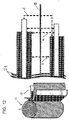
- Figure 13 is a schematic diagram showing an alternative embodiment of a switch 100. By locating the load 101 outside the cell 110, stored energy can be removed from the cell 110 bringing it to a safe state. Dissipating the stored energy in a controlled manner may help prevent or lessen the severity of a possible thermal event.
Landscapes
- Chemical & Material Sciences (AREA)
- Chemical Kinetics & Catalysis (AREA)
- Electrochemistry (AREA)
- General Chemical & Material Sciences (AREA)
- Engineering & Computer Science (AREA)
- Manufacturing & Machinery (AREA)
- Secondary Cells (AREA)
Claims (15)
- Passive Sicherheitsvorrichtung (10) für eine Energiespeicherzelle zum Positionieren zwischen zwei elektrisch leitfähigen Schichten der Energiespeicherzelle, die Vorrichtung umfassend:ein Trennelement;eine nicht leitfähige Schicht;ein erstes elektrisch leitfähiges Material (14), das auf der nicht leitfähigen Schicht (12) bereitgestellt ist;eine erste Öffnung (20a), die durch das Trennelement (18) zwischen dem ersten elektrisch leitfähigen Material (14) und einer der elektrisch leitfähigen Schichten der Energiespeicherzelle gebildet ist;ein zweites elektrisch leitfähiges Material (14), das anliegend am ersten elektrisch leitfähigen Material (14) auf der nicht leitfähigen Schicht (12) bereitgestellt ist, wobei ein Raum (16) auf der nicht leitfähigen Schicht zwischen dem ersten und zweiten elektrisch leitfähigen Material (14) gebildet ist;eine zweite Öffnung (20b), die durch die nicht leitfähige Schicht (12) zwischen dem zweiten elektrisch leitfähigen Material (14) und einer anderen der elektrisch leitfähigen Schichten der Energiespeicherzelle gebildet ist; undwobei das erste und zweite elektrisch leitfähige Material (14) kombiniert sind und mindestens teilweise durch die erste und zweite Öffnung (20a-b) austreten, um die zwei elektrisch leitfähigen Schichten der Energiespeicherzelle bei einer vorbestimmten Temperatur zu verbinden.
- Vorrichtung (10) nach Anspruch 1, wobei das Trennelement (18) aus einem Material ist, das einem Material ähnlich ist, das bereits in der Energiespeicherzelle verwendet wird.
- Vorrichtung (10) nach Anspruch 1, wobei das erste und zweite elektrisch leitfähige Material (14) auf die nicht leitfähige Schicht (12) durch mindestens einen der folgenden Prozesse aufgebracht wird: chemische Gasphasenabscheidung, plasmaverstärkte chemische Gasphasenabscheidung, physikalische Gasphasenabscheidung, thermischer Verdampfer, Elektronenstrahlverdampfer, Sputtern und Plattieren.
- Vorrichtung (10) nach Anspruch 1, wobei das Trennelement (18) einen Schmelzpunkt im Bereich von ca. 10 bis 150 °C hat.
- Vorrichtung (10) nach Anspruch 1, wobei das erste und zweite elektrisch leitfähige Material (14) verschiedene Schmelztemperaturen haben.
- Vorrichtung (10) nach Anspruch 1, wobei das erste und zweite elektrisch leitfähige Material (14) in mindestens einer der folgenden Konfigurationen positioniert sind: zwischen aktiven Materialbeschichtungen von Kathode und Anode, zwischen einer Kathode (24) und dem Stromabnehmer der negativen Elektrode, zwischen einer Anode (24) und einem Stromabnehmer einer positiven Elektrode und zwischen positiven und negativen Stromabnehmern.
- Verfahren zum Erzeugen eines elektrischen Kurzschlusses zwischen zwei elektrisch leitfähige Schichten der Energiespeicherzelle, das Verfahren umfassend:Bereitstellen eines ersten elektrisch leitfähigen Materials (14) auf einer nicht leitfähigen Schicht (12);Bilden einer ersten Öffnung (20a) durch ein Trennelement (18) zwischen dem ersten elektrisch leitfähigen Material (14) und einer der elektrisch leitfähigen Schichten der Energiespeicherzelle;Bereitstellen eines zweiten elektrisch leitfähigen Materials (14) anliegend am ersten elektrisch leitfähigen Material (14) auf der nicht leitfähigen Schicht (12), wobei ein Raum (16) auf der nicht leitfähigen Schicht (12) zwischen dem ersten und zweiten elektrisch leitfähigen Material (14) gebildet ist;Bilden einer zweiten Öffnung (20b) durch die nicht leitfähige Schicht (12) zwischen dem zweiten elektrisch leitfähigen Material (14) und einer anderen der elektrisch leitfähigen Schichten der Energiespeicherzelle; undKombinieren des ersten und zweiten elektrisch leitfähigen Materials (14), um mindestens teilweise durch die erste und zweite Öffnung (20a-b) auszutreten, um die zwei elektrisch leitfähigen Schichten der Energiespeicherzelle bei einer vorbestimmten Temperatur zu verbinden.
- Verfahren nach Anspruch 7, ferner umfassend ein Bereitstellen des Trennelements (18) aus einem Material, das einem Material ähnlich ist, das bereits in der Energiespeicherzelle verwendet wird.
- Verfahren nach Anspruch 7, ferner umfassend ein Aufbringen des ersten und zweiten elektrisch leitfähigen Materials (14) auf der nicht leitfähigen Schicht (12) durch mindestens einen der folgenden Prozesse: chemische Gasphasenabscheidung, plasmaverstärkte chemische Gasphasenabscheidung, physikalische Gasphasenabscheidung, thermischer Verdampfer, Elektronenstrahlverdampfer, Sputtern und Plattieren.
- Verfahren nach Anspruch 7, wobei das erste und zweite elektrisch leitfähige Material (14) in einem Temperaturbereich von ca. 10 bis 150 °C kombiniert werden.
- Verfahren nach Anspruch 7, wobei das erste und zweite elektrisch leitfähige Material (14) verschiedene Kombinationstemperaturen haben.
- Verfahren nach Anspruch 7, ferner umfassend ein Bereitstellen verschiedener Kurzschlusskonfigurationen, wobei die verschiedenen Kurzschlusskonfigurationen mindestens eine der folgenden sind: zwischen aktiven Materialbeschichtungen von Kathode und Anode, zwischen einem Stromabnehmer einer Kathode (24) und einer negativen Elektrode, zwischen einem Stromabnehmer von einer Anode (24) und der positiven Elektrode und zwischen Stromabnehmern von positiver und negativer Elektrode.
- Vorrichtung nach Anspruch 1 oder Verfahren nach Anspruch 7, wobei das Trennelement (18) eine Länge und Breite im Bereich von ca. 0,0127 cm bis 12,7 cm (0,0050 bis 5 Zoll) hat.
- Vorrichtung nach Anspruch 1 oder Verfahren nach Anspruch 7, wobei das erste und zweite elektrisch leitfähige Material (14) eine Stärke von weniger als ca. 500 µm (500 Mikrometer) haben.
- Vorrichtung nach Anspruch 1 oder Verfahren nach Anspruch 7, wobei der Raum (16) im Bereich von ca. 0,00127 cm bis 0,635 cm (0,0005 bis 0,25 Zoll) ist.
Applications Claiming Priority (1)
| Application Number | Priority Date | Filing Date | Title |
|---|---|---|---|
| PCT/US2010/054301 WO2012057752A1 (en) | 2010-10-27 | 2010-10-27 | Passive safety device and internal short tested method for energy storage cells and systems |
Publications (3)
| Publication Number | Publication Date |
|---|---|
| EP2633585A1 EP2633585A1 (de) | 2013-09-04 |
| EP2633585A4 EP2633585A4 (de) | 2016-04-13 |
| EP2633585B1 true EP2633585B1 (de) | 2017-05-24 |
Family
ID=45994224
Family Applications (1)
| Application Number | Title | Priority Date | Filing Date |
|---|---|---|---|
| EP10859069.6A Active EP2633585B1 (de) | 2010-10-27 | 2010-10-27 | Passive sicherheitsvorrichtung und internes kurzschlussgeprüftes verfahren für energiespeicherzellen und systeme |
Country Status (3)
| Country | Link |
|---|---|
| US (1) | US9142829B2 (de) |
| EP (1) | EP2633585B1 (de) |
| WO (1) | WO2012057752A1 (de) |
Families Citing this family (20)
| Publication number | Priority date | Publication date | Assignee | Title |
|---|---|---|---|---|
| JP5958142B2 (ja) * | 2012-07-20 | 2016-07-27 | 株式会社Gsユアサ | 短絡素子、蓄電素子、および蓄電素子システム |
| JP5958141B2 (ja) * | 2012-07-20 | 2016-07-27 | 株式会社Gsユアサ | 蓄電素子および蓄電素子システム |
| DE102012213697A1 (de) * | 2012-08-02 | 2014-02-06 | Robert Bosch Gmbh | Sensorvorrichtung und Verfahren zum Bestimmen eines Druckes eines innerhalb eines elektrochemischen Energiespeichers befindlichen Mediums, elektrochemischer Energiespeicher und Verfahren zum Herstellen desselben |
| CN103280597B (zh) * | 2013-05-31 | 2017-09-29 | 宁德新能源科技有限公司 | 锂离子电池 |
| EP3193389A1 (de) * | 2016-01-13 | 2017-07-19 | Lithium Energy and Power GmbH & Co. KG | Wiederaufladbares batteriemodul |
| US20180095139A1 (en) * | 2016-09-30 | 2018-04-05 | Faraday&Future Inc. | Passive propagation test fixture |
| DE102018200796A1 (de) * | 2018-01-18 | 2019-07-18 | Bayerische Motoren Werke Aktiengesellschaft | Testvorrichtung für eine elektrochemische Zelle, Baugruppe mit einer Testvorrichtung und Verfahren zum Testen einer elektrochemischen Zelle |
| US11355824B2 (en) | 2018-05-11 | 2022-06-07 | The Regents Of The University Of Michigan | Detection of an internal short circuit in a battery |
| US11043705B1 (en) * | 2018-05-25 | 2021-06-22 | The United States Government Of America As Represented By The Secretary Of The Navy | Cell having implanted electronic circuit |
| KR102261177B1 (ko) | 2018-08-01 | 2021-06-07 | 주식회사 엘지에너지솔루션 | 내부단락 시험용 이차전지, 이를 이용한 이차전지 내부단락 시험 방법 및 장치 |
| KR102465778B1 (ko) * | 2018-10-05 | 2022-11-14 | 주식회사 엘지에너지솔루션 | 이차전지 |
| KR102453053B1 (ko) * | 2018-11-02 | 2022-10-11 | 주식회사 엘지에너지솔루션 | 이차전지 내부 단락 평가 방법 |
| KR102656799B1 (ko) * | 2018-11-09 | 2024-04-12 | 주식회사 엘지에너지솔루션 | 전지의 내부단락 유도장치, 이를 포함하는 전지 및 전지의 내부단락을 통한 안전성 평가방법 |
| KR102760120B1 (ko) | 2019-04-09 | 2025-01-24 | 주식회사 엘지에너지솔루션 | 단락 유도 부재를 포함하는 전지셀 및 이를 이용한 안전성 평가방법 |
| KR102734360B1 (ko) * | 2019-08-07 | 2024-11-27 | 주식회사 엘지에너지솔루션 | 내부 단락 유도를 위한 전기화학소자 및 이를 이용한 안전성 평가방법 |
| KR102760183B1 (ko) * | 2019-08-09 | 2025-02-03 | 주식회사 엘지에너지솔루션 | 단락유도부재를 포함하는 전기화학소자 및 이를 이용한 안전성 평가방법 |
| KR102707193B1 (ko) | 2019-12-17 | 2024-09-20 | 주식회사 엘지에너지솔루션 | 내부 단락 평가용 전지 셀 및 이를 이용한 전지 셀의 내부 단락 평가 방법 |
| KR102900628B1 (ko) | 2021-11-02 | 2025-12-15 | 주식회사 엘지에너지솔루션 | 단락 유도 평가용 이차전지, 이의 제조방법 및 이차전지의 안전성 평가 방법 |
| KR20230082260A (ko) * | 2021-12-01 | 2023-06-08 | 주식회사 엘지에너지솔루션 | 배터리 내부 단락 유발 장치 및 방법 |
| DE102023202213A1 (de) | 2023-03-13 | 2024-09-19 | Volkswagen Aktiengesellschaft | Verfahren zur gezielten Erzeugung eines Kurzschlusses in einer Batteriezelle, eine Anordnung für eine Batteriezelle sowie eine Batteriezelle |
Family Cites Families (5)
| Publication number | Priority date | Publication date | Assignee | Title |
|---|---|---|---|---|
| US5500503A (en) | 1994-08-04 | 1996-03-19 | Midwest Research Institute | Simultaneous laser cutting and welding of metal foil to edge of a plate |
| US6858811B2 (en) | 2001-06-07 | 2005-02-22 | Bed-Check Corporation | Binary switch apparatus and method for manufacturing same |
| US6891353B2 (en) | 2001-11-07 | 2005-05-10 | Quallion Llc | Safety method, device and system for an energy storage device |
| JP4207686B2 (ja) * | 2003-07-01 | 2009-01-14 | パナソニック株式会社 | ヒューズ、それを用いたパック電池およびヒューズ製造方法 |
| US8163409B2 (en) * | 2006-12-15 | 2012-04-24 | Panasonic Corporation | Evaluation method for safety upon battery internal short circuit, evaluation device for safety upon battery internal short circuit, battery, battery pack, and manufacturing method for battery and battery pack |
-
2010
- 2010-10-27 WO PCT/US2010/054301 patent/WO2012057752A1/en not_active Ceased
- 2010-10-27 US US13/882,316 patent/US9142829B2/en active Active
- 2010-10-27 EP EP10859069.6A patent/EP2633585B1/de active Active
Also Published As
| Publication number | Publication date |
|---|---|
| US9142829B2 (en) | 2015-09-22 |
| EP2633585A1 (de) | 2013-09-04 |
| WO2012057752A1 (en) | 2012-05-03 |
| EP2633585A4 (de) | 2016-04-13 |
| US20130209841A1 (en) | 2013-08-15 |
Similar Documents
| Publication | Publication Date | Title |
|---|---|---|
| US9142829B2 (en) | Passive safety device and internal short tested method for energy storage cells and systems | |
| Venugopal | Characterization of thermal cut-off mechanisms in prismatic lithium-ion batteries | |
| JP7837062B2 (ja) | 内部ヒューズを有するリチウムエネルギー貯蔵デバイス | |
| Abaza et al. | Experimental study of internal and external short circuits of commercial automotive pouch lithium-ion cells | |
| Zhao et al. | Modeling internal shorting process in large-format Li-ion cells | |
| JP5086496B2 (ja) | 安全性評価用二次電池及び二次電池の試験方法 | |
| JP4084926B2 (ja) | 電気化学電池用の破壊制御機構 | |
| KR102926584B1 (ko) | 낮은 내부 저항을 갖는 금속화 필름 집전체를 갖춘 배터리 | |
| JP4267812B2 (ja) | 高エネルギー電気化学セルのための現場短絡保護システム及び方法 | |
| US8263254B2 (en) | Cell with an outer layer of intumescent material | |
| Juarez-Robles et al. | Degradation-safety analytics in lithium-ion cells and modules: Part III. Aging and safety of pouch format cells | |
| US11043705B1 (en) | Cell having implanted electronic circuit | |
| KR101037042B1 (ko) | 안전성이 개선된 파우치형 이차전지 | |
| JP7706164B2 (ja) | 内部ヒューズを有する蓄電装置のバッテリ接続および金属化膜部品 | |
| RU2340983C1 (ru) | Аккумуляторная батарея, имеющая повышенную защиту | |
| Jones et al. | Determining the effects of non-catastrophic nail puncture on the operational performance and service life of small soft case commercial Li-ion prismatic cells | |
| US20240072399A1 (en) | Disconnection device and short-circuiting device comprising a heat-activatable element | |
| Darikas et al. | Analysis of internal cell temperature variations under different abuse test conditions using embedded temperature sensors | |
| Darst et al. | Guidelines for Safe, High Performing Li-ion Battery Designs for Manned Vehicles | |
| CN120978359B (zh) | 基于电压触发的锂离子电池嵌入式安全装置、控制方法及电池 | |
| JPH1154005A (ja) | 電流・温度複合ヒューズ、及びこれを用いた二次電池用保護素子 | |
| Darcy | Safe, High Performing Batteries for Manned Spacecraft Applications | |
| Sawlsville | Battery Safety: A systematic study of battery performance under extreme conditions | |
| Troutman et al. | ABSL Initial Performance Comparison of Sony 18650 Hard Carbon cell and Sony 18650 Hard Carbon Mandrel Cell | |
| EP3193389A1 (de) | Wiederaufladbares batteriemodul |
Legal Events
| Date | Code | Title | Description |
|---|---|---|---|
| PUAI | Public reference made under article 153(3) epc to a published international application that has entered the european phase |
Free format text: ORIGINAL CODE: 0009012 |
|
| 17P | Request for examination filed |
Effective date: 20130506 |
|
| AK | Designated contracting states |
Kind code of ref document: A1 Designated state(s): AL AT BE BG CH CY CZ DE DK EE ES FI FR GB GR HR HU IE IS IT LI LT LU LV MC MK MT NL NO PL PT RO RS SE SI SK SM TR |
|
| DAX | Request for extension of the european patent (deleted) | ||
| REG | Reference to a national code |
Ref country code: DE Ref legal event code: R079 Ref document number: 602010042606 Country of ref document: DE Free format text: PREVIOUS MAIN CLASS: H01M0012000000 Ipc: H01M0002340000 |
|
| RA4 | Supplementary search report drawn up and despatched (corrected) |
Effective date: 20160316 |
|
| RIC1 | Information provided on ipc code assigned before grant |
Ipc: H01H 3/00 20060101ALI20160310BHEP Ipc: H01M 2/34 20060101AFI20160310BHEP Ipc: H01M 10/42 20060101ALI20160310BHEP |
|
| GRAP | Despatch of communication of intention to grant a patent |
Free format text: ORIGINAL CODE: EPIDOSNIGR1 |
|
| RAP1 | Party data changed (applicant data changed or rights of an application transferred) |
Owner name: UNITED STATES OF AMERICA AS REPRESENTED BY THE ADM Owner name: ALLIANCE FOR SUSTAINABLE ENERGY, LLC |
|
| INTG | Intention to grant announced |
Effective date: 20161208 |
|
| GRAS | Grant fee paid |
Free format text: ORIGINAL CODE: EPIDOSNIGR3 |
|
| GRAA | (expected) grant |
Free format text: ORIGINAL CODE: 0009210 |
|
| AK | Designated contracting states |
Kind code of ref document: B1 Designated state(s): AL AT BE BG CH CY CZ DE DK EE ES FI FR GB GR HR HU IE IS IT LI LT LU LV MC MK MT NL NO PL PT RO RS SE SI SK SM TR |
|
| REG | Reference to a national code |
Ref country code: GB Ref legal event code: FG4D |
|
| REG | Reference to a national code |
Ref country code: CH Ref legal event code: EP |
|
| REG | Reference to a national code |
Ref country code: IE Ref legal event code: FG4D |
|
| REG | Reference to a national code |
Ref country code: AT Ref legal event code: REF Ref document number: 896403 Country of ref document: AT Kind code of ref document: T Effective date: 20170615 |
|
| REG | Reference to a national code |
Ref country code: DE Ref legal event code: R096 Ref document number: 602010042606 Country of ref document: DE |
|
| REG | Reference to a national code |
Ref country code: FR Ref legal event code: PLFP Year of fee payment: 8 |
|
| REG | Reference to a national code |
Ref country code: NL Ref legal event code: MP Effective date: 20170524 |
|
| REG | Reference to a national code |
Ref country code: LT Ref legal event code: MG4D |
|
| REG | Reference to a national code |
Ref country code: AT Ref legal event code: MK05 Ref document number: 896403 Country of ref document: AT Kind code of ref document: T Effective date: 20170524 |
|
| PG25 | Lapsed in a contracting state [announced via postgrant information from national office to epo] |
Ref country code: ES Free format text: LAPSE BECAUSE OF FAILURE TO SUBMIT A TRANSLATION OF THE DESCRIPTION OR TO PAY THE FEE WITHIN THE PRESCRIBED TIME-LIMIT Effective date: 20170524 Ref country code: NO Free format text: LAPSE BECAUSE OF FAILURE TO SUBMIT A TRANSLATION OF THE DESCRIPTION OR TO PAY THE FEE WITHIN THE PRESCRIBED TIME-LIMIT Effective date: 20170824 Ref country code: LT Free format text: LAPSE BECAUSE OF FAILURE TO SUBMIT A TRANSLATION OF THE DESCRIPTION OR TO PAY THE FEE WITHIN THE PRESCRIBED TIME-LIMIT Effective date: 20170524 Ref country code: FI Free format text: LAPSE BECAUSE OF FAILURE TO SUBMIT A TRANSLATION OF THE DESCRIPTION OR TO PAY THE FEE WITHIN THE PRESCRIBED TIME-LIMIT Effective date: 20170524 Ref country code: HR Free format text: LAPSE BECAUSE OF FAILURE TO SUBMIT A TRANSLATION OF THE DESCRIPTION OR TO PAY THE FEE WITHIN THE PRESCRIBED TIME-LIMIT Effective date: 20170524 Ref country code: AT Free format text: LAPSE BECAUSE OF FAILURE TO SUBMIT A TRANSLATION OF THE DESCRIPTION OR TO PAY THE FEE WITHIN THE PRESCRIBED TIME-LIMIT Effective date: 20170524 Ref country code: GR Free format text: LAPSE BECAUSE OF FAILURE TO SUBMIT A TRANSLATION OF THE DESCRIPTION OR TO PAY THE FEE WITHIN THE PRESCRIBED TIME-LIMIT Effective date: 20170825 |
|
| PG25 | Lapsed in a contracting state [announced via postgrant information from national office to epo] |
Ref country code: LV Free format text: LAPSE BECAUSE OF FAILURE TO SUBMIT A TRANSLATION OF THE DESCRIPTION OR TO PAY THE FEE WITHIN THE PRESCRIBED TIME-LIMIT Effective date: 20170524 Ref country code: RS Free format text: LAPSE BECAUSE OF FAILURE TO SUBMIT A TRANSLATION OF THE DESCRIPTION OR TO PAY THE FEE WITHIN THE PRESCRIBED TIME-LIMIT Effective date: 20170524 Ref country code: NL Free format text: LAPSE BECAUSE OF FAILURE TO SUBMIT A TRANSLATION OF THE DESCRIPTION OR TO PAY THE FEE WITHIN THE PRESCRIBED TIME-LIMIT Effective date: 20170524 Ref country code: SE Free format text: LAPSE BECAUSE OF FAILURE TO SUBMIT A TRANSLATION OF THE DESCRIPTION OR TO PAY THE FEE WITHIN THE PRESCRIBED TIME-LIMIT Effective date: 20170524 Ref country code: BG Free format text: LAPSE BECAUSE OF FAILURE TO SUBMIT A TRANSLATION OF THE DESCRIPTION OR TO PAY THE FEE WITHIN THE PRESCRIBED TIME-LIMIT Effective date: 20170824 Ref country code: IS Free format text: LAPSE BECAUSE OF FAILURE TO SUBMIT A TRANSLATION OF THE DESCRIPTION OR TO PAY THE FEE WITHIN THE PRESCRIBED TIME-LIMIT Effective date: 20170924 |
|
| PG25 | Lapsed in a contracting state [announced via postgrant information from national office to epo] |
Ref country code: CZ Free format text: LAPSE BECAUSE OF FAILURE TO SUBMIT A TRANSLATION OF THE DESCRIPTION OR TO PAY THE FEE WITHIN THE PRESCRIBED TIME-LIMIT Effective date: 20170524 Ref country code: RO Free format text: LAPSE BECAUSE OF FAILURE TO SUBMIT A TRANSLATION OF THE DESCRIPTION OR TO PAY THE FEE WITHIN THE PRESCRIBED TIME-LIMIT Effective date: 20170524 Ref country code: SK Free format text: LAPSE BECAUSE OF FAILURE TO SUBMIT A TRANSLATION OF THE DESCRIPTION OR TO PAY THE FEE WITHIN THE PRESCRIBED TIME-LIMIT Effective date: 20170524 Ref country code: EE Free format text: LAPSE BECAUSE OF FAILURE TO SUBMIT A TRANSLATION OF THE DESCRIPTION OR TO PAY THE FEE WITHIN THE PRESCRIBED TIME-LIMIT Effective date: 20170524 Ref country code: DK Free format text: LAPSE BECAUSE OF FAILURE TO SUBMIT A TRANSLATION OF THE DESCRIPTION OR TO PAY THE FEE WITHIN THE PRESCRIBED TIME-LIMIT Effective date: 20170524 |
|
| REG | Reference to a national code |
Ref country code: DE Ref legal event code: R097 Ref document number: 602010042606 Country of ref document: DE |
|
| PG25 | Lapsed in a contracting state [announced via postgrant information from national office to epo] |
Ref country code: PL Free format text: LAPSE BECAUSE OF FAILURE TO SUBMIT A TRANSLATION OF THE DESCRIPTION OR TO PAY THE FEE WITHIN THE PRESCRIBED TIME-LIMIT Effective date: 20170524 Ref country code: IT Free format text: LAPSE BECAUSE OF FAILURE TO SUBMIT A TRANSLATION OF THE DESCRIPTION OR TO PAY THE FEE WITHIN THE PRESCRIBED TIME-LIMIT Effective date: 20170524 Ref country code: SM Free format text: LAPSE BECAUSE OF FAILURE TO SUBMIT A TRANSLATION OF THE DESCRIPTION OR TO PAY THE FEE WITHIN THE PRESCRIBED TIME-LIMIT Effective date: 20170524 |
|
| PLBE | No opposition filed within time limit |
Free format text: ORIGINAL CODE: 0009261 |
|
| STAA | Information on the status of an ep patent application or granted ep patent |
Free format text: STATUS: NO OPPOSITION FILED WITHIN TIME LIMIT |
|
| 26N | No opposition filed |
Effective date: 20180227 |
|
| PG25 | Lapsed in a contracting state [announced via postgrant information from national office to epo] |
Ref country code: SI Free format text: LAPSE BECAUSE OF FAILURE TO SUBMIT A TRANSLATION OF THE DESCRIPTION OR TO PAY THE FEE WITHIN THE PRESCRIBED TIME-LIMIT Effective date: 20170524 Ref country code: MC Free format text: LAPSE BECAUSE OF FAILURE TO SUBMIT A TRANSLATION OF THE DESCRIPTION OR TO PAY THE FEE WITHIN THE PRESCRIBED TIME-LIMIT Effective date: 20170524 |
|
| REG | Reference to a national code |
Ref country code: CH Ref legal event code: PL |
|
| REG | Reference to a national code |
Ref country code: IE Ref legal event code: MM4A |
|
| PG25 | Lapsed in a contracting state [announced via postgrant information from national office to epo] |
Ref country code: LI Free format text: LAPSE BECAUSE OF NON-PAYMENT OF DUE FEES Effective date: 20171031 Ref country code: LU Free format text: LAPSE BECAUSE OF NON-PAYMENT OF DUE FEES Effective date: 20171027 Ref country code: CH Free format text: LAPSE BECAUSE OF NON-PAYMENT OF DUE FEES Effective date: 20171031 |
|
| REG | Reference to a national code |
Ref country code: BE Ref legal event code: MM Effective date: 20171031 |
|
| PG25 | Lapsed in a contracting state [announced via postgrant information from national office to epo] |
Ref country code: BE Free format text: LAPSE BECAUSE OF NON-PAYMENT OF DUE FEES Effective date: 20171031 |
|
| REG | Reference to a national code |
Ref country code: FR Ref legal event code: PLFP Year of fee payment: 9 |
|
| PG25 | Lapsed in a contracting state [announced via postgrant information from national office to epo] |
Ref country code: MT Free format text: LAPSE BECAUSE OF NON-PAYMENT OF DUE FEES Effective date: 20171027 |
|
| PG25 | Lapsed in a contracting state [announced via postgrant information from national office to epo] |
Ref country code: IE Free format text: LAPSE BECAUSE OF NON-PAYMENT OF DUE FEES Effective date: 20171027 |
|
| PG25 | Lapsed in a contracting state [announced via postgrant information from national office to epo] |
Ref country code: HU Free format text: LAPSE BECAUSE OF FAILURE TO SUBMIT A TRANSLATION OF THE DESCRIPTION OR TO PAY THE FEE WITHIN THE PRESCRIBED TIME-LIMIT; INVALID AB INITIO Effective date: 20101027 |
|
| PG25 | Lapsed in a contracting state [announced via postgrant information from national office to epo] |
Ref country code: CY Free format text: LAPSE BECAUSE OF NON-PAYMENT OF DUE FEES Effective date: 20170524 |
|
| PG25 | Lapsed in a contracting state [announced via postgrant information from national office to epo] |
Ref country code: MK Free format text: LAPSE BECAUSE OF FAILURE TO SUBMIT A TRANSLATION OF THE DESCRIPTION OR TO PAY THE FEE WITHIN THE PRESCRIBED TIME-LIMIT Effective date: 20170524 |
|
| PG25 | Lapsed in a contracting state [announced via postgrant information from national office to epo] |
Ref country code: TR Free format text: LAPSE BECAUSE OF FAILURE TO SUBMIT A TRANSLATION OF THE DESCRIPTION OR TO PAY THE FEE WITHIN THE PRESCRIBED TIME-LIMIT Effective date: 20170524 |
|
| PG25 | Lapsed in a contracting state [announced via postgrant information from national office to epo] |
Ref country code: PT Free format text: LAPSE BECAUSE OF FAILURE TO SUBMIT A TRANSLATION OF THE DESCRIPTION OR TO PAY THE FEE WITHIN THE PRESCRIBED TIME-LIMIT Effective date: 20170524 |
|
| PG25 | Lapsed in a contracting state [announced via postgrant information from national office to epo] |
Ref country code: AL Free format text: LAPSE BECAUSE OF FAILURE TO SUBMIT A TRANSLATION OF THE DESCRIPTION OR TO PAY THE FEE WITHIN THE PRESCRIBED TIME-LIMIT Effective date: 20170524 |
|
| REG | Reference to a national code |
Ref country code: DE Ref legal event code: R079 Ref document number: 602010042606 Country of ref document: DE Free format text: PREVIOUS MAIN CLASS: H01M0002340000 Ipc: H01M0050572000 |
|
| P01 | Opt-out of the competence of the unified patent court (upc) registered |
Effective date: 20230623 |
|
| PGFP | Annual fee paid to national office [announced via postgrant information from national office to epo] |
Ref country code: GB Payment date: 20250911 Year of fee payment: 16 |
|
| PGFP | Annual fee paid to national office [announced via postgrant information from national office to epo] |
Ref country code: FR Payment date: 20250912 Year of fee payment: 16 |
|
| PGFP | Annual fee paid to national office [announced via postgrant information from national office to epo] |
Ref country code: DE Payment date: 20250912 Year of fee payment: 16 |