EP2633723B1 - Système et procédé pour contrôler des interférences dans des systèmes de transmission simultanée - Google Patents
Système et procédé pour contrôler des interférences dans des systèmes de transmission simultanée Download PDFInfo
- Publication number
- EP2633723B1 EP2633723B1 EP11846074.0A EP11846074A EP2633723B1 EP 2633723 B1 EP2633723 B1 EP 2633723B1 EP 11846074 A EP11846074 A EP 11846074A EP 2633723 B1 EP2633723 B1 EP 2633723B1
- Authority
- EP
- European Patent Office
- Prior art keywords
- radio
- interference
- power
- priority
- receiver
- Prior art date
- Legal status (The legal status is an assumption and is not a legal conclusion. Google has not performed a legal analysis and makes no representation as to the accuracy of the status listed.)
- Not-in-force
Links
Images


Classifications
-
- H—ELECTRICITY
- H04—ELECTRIC COMMUNICATION TECHNIQUE
- H04B—TRANSMISSION
- H04B1/00—Details of transmission systems, not covered by a single one of groups H04B3/00 - H04B13/00; Details of transmission systems not characterised by the medium used for transmission
- H04B1/38—Transceivers, i.e. devices in which transmitter and receiver form a structural unit and in which at least one part is used for functions of transmitting and receiving
- H04B1/40—Circuits
- H04B1/50—Circuits using different frequencies for the two directions of communication
- H04B1/52—Hybrid arrangements, i.e. arrangements for transition from single-path two-direction transmission to single-direction transmission on each of two paths or vice versa
- H04B1/525—Hybrid arrangements, i.e. arrangements for transition from single-path two-direction transmission to single-direction transmission on each of two paths or vice versa with means for reducing leakage of transmitter signal into the receiver
-
- H—ELECTRICITY
- H04—ELECTRIC COMMUNICATION TECHNIQUE
- H04B—TRANSMISSION
- H04B17/00—Monitoring; Testing
- H04B17/10—Monitoring; Testing of transmitters
- H04B17/11—Monitoring; Testing of transmitters for calibration
- H04B17/14—Monitoring; Testing of transmitters for calibration of the whole transmission and reception path, e.g. self-test loop-back
-
- H—ELECTRICITY
- H04—ELECTRIC COMMUNICATION TECHNIQUE
- H04B—TRANSMISSION
- H04B17/00—Monitoring; Testing
- H04B17/20—Monitoring; Testing of receivers
- H04B17/29—Performance testing
-
- H—ELECTRICITY
- H04—ELECTRIC COMMUNICATION TECHNIQUE
- H04W—WIRELESS COMMUNICATION NETWORKS
- H04W52/00—Power management, e.g. Transmission Power Control [TPC] or power classes
- H04W52/04—Transmission power control [TPC]
- H04W52/30—Transmission power control [TPC] using constraints in the total amount of available transmission power
- H04W52/36—Transmission power control [TPC] using constraints in the total amount of available transmission power with a discrete range or set of values, e.g. step size, ramping or offsets
- H04W52/367—Power values between minimum and maximum limits, e.g. dynamic range
Definitions
- Wireless communication systems generally incorporate many different types of wireless devices, such as mobile phones, data cards, Universal Serial Bus (“USB”) dongles, hot-spots, wireless modems, and the like. These systems may utilize simultaneous transmission from more than one transmitter.
- self-interference may affect non-linear radio frequency devices where more than one transmitter is simultaneously transmitting while at least one receiver is actively receiving.
- This self-interference sometimes referred to as crosstalk, self-jamming, or transmitter leakage, generally results from coupling of a transmitted signal to the active receiver.
- the transmission signal may pass through non-linear circuits via radiative coupling, conductive coupling, inductive coupling, magnetic coupling, very-large-scale integration (VLSI) chip coupling, etc.
- VLSI very-large-scale integration
- An output of a non-linear circuit may generate an interference signal with varying spectrum shape, and bandwidth at a radio frequency that may fall within proximity of the carrier frequency of an active receiver in the device. Due to limited isolation, the generated interference signal may leak (e.g., through a duplexer filter) and couple to an input path of the active receiver.
- the coupled interference signal can degrade the reception performance of the receiver in multiple ways such as reducing dynamic range, increasing noise floor, and potentially contributing additional interference generations with other coupled signals in the receiver path through non-linear stages.
- filtering may be limited to non-linear front-end components and/or first non-linear blocks on the paths of the transmitters and the receiver of interest.
- the generated interference may fall within or in close proximity to the receiver band of interest, and filtering may not be a useful or sufficient solution.
- the interference may fall outside of the receiver channel bandwidth, but close enough that the filtering in radio frequencies are not sufficient.
- the filtering may be extended to baseband by maintaining the dynamic range at a high level in order to prevent any further non-linear distortion.
- high dynamic range may result in high power consumption and high design costs.
- One method in the second group may include cancelling interference at certain radio frequency stages.
- Another method may include using baseband signal processing to re-generate an interference signal and cancel it at certain radio frequencies.
- a method to control the generation of interference according to the third group may include using components of high linearity on the signal paths.
- components with high linearity requirements might not be commercially available, and might necessitate high costs and/or designs that are not commercially available.
- Another method according to the third group may include planning simultaneous operating frequencies such that no significant interference generation adversely affects the receiver operations. However, this limits the flexibility of network planning on the operator side. Another available method is to limit maximum power levels when two or more transmitters are active. For instance, this may be useful when simultaneously transmitting via a 1x radio transmission technology (1xRTT) network (e.g., for voice) and a long-term evolution (LTE) network (e.g., for data). However, limiting power levels in such cases may generally not be seen optimal as some other factors can determine the level or impact of interference, such as varying frequencies, spectral shapes of transmitting and receiving signals, received signal levels, temperature, etc.
- 1xRTT 1x radio transmission technology
- LTE long-term evolution
- WO 2012/051952 A1 discloses a hybrid FDM/TDM solution for in-device coexistence interference avoidance, in which a user equipment (UE) having a first radio transceiver and a second co-located radio transceiver detects coexistence interference between the two radios based on radio signal measurement.
- the UE sends an IDC interference indictor to its serving station (eNB).
- the UE reports IDC information including recommendation for FDM and TDM configurations to the eNB.
- the eNB receives the IDC interference indicator and evaluates whether to trigger DFM-based solution to mitigate coexistence interference.
- the eNB also evaluates whether to trigger TDM-based solution to mitigate coexistence interference.
- the evaluation is based on the recommended FDM and TDM configuration.
- the eNB may trigger FDM-based, TDM-based solution, or FDM and TDM solution based on the evaluation results of the feasibility and effectiveness of each solution.
- WO 2010/089281 A1 discloses that a communication device has a plurality of concurrently operating transceivers, each operating in a respectively different one of a plurality of communication systems, wherein the plurality of concurrently operating transceivers includes a first transceiver and a second transceiver. Operation of the communication device includes the first transceiver ascertaining whether transmissions by the second transceiver are causing interference in a receiver of the first transceiver and if so, performing one or more interference response actions. The one or more interference response actions include ascertaining whether the interference is at an acceptable level and if so then taking no further interference response actions. If the interference is ascertained to be at an unacceptable level, an interference mitigation request is communicated to the second transceiver.
- the second transceiver can, for example, shift its use of frequencies to a region whereby the first transceiver's band select filter can sufficiently attenuate the second transceiver's signal.
- a wireless device connecting to one or more particular networks such as Third Generation Partnership Project (3GPP) long-term evolution (LTE) and 3GPP2 1x radio transmission technology (1xRTT) networks.
- 3GPP Third Generation Partnership Project
- LTE long-term evolution
- 1xRTT 3GPP2 1x radio transmission technology
- CDMA Code Division Multiple Access
- TDMA Time Division Multiple Access
- FDMA Frequency Division Multiple Access
- OFDMA Orthogonal FDMA
- SC-FDMA Single-Carrier FDMA
- a wireless communication network may implement any suitable radio technologies.
- a CDMA network may implement a radio technology such as Universal Terrestrial Radio Access (UTRA), Wideband-CDMA (W-CDMA), CDMA 2000, etc.
- a TDMA network may implement a radio technology such as Global System for Mobile Communications (GSM).
- GSM Global System for Mobile Communications
- An OFDMA network may implement a radio technology such as Evolved UTRA (E-UTRA), the Institute of Electrical and Electronics Engineers (IEEE) 802.11, IEEE 802.16, IEEE 802.20, Flash-OFDM®, etc.
- E-UTRA Evolved UTRA
- IEEE Institute of Electrical and Electronics Engineers
- IEEE 802.20 IEEE 802.20
- Flash-OFDM® Flash-OFDM®
- Communication devices such as mobile phones and data cards may be designed to connect to multiple networks such as a 3GPP LTE network and a 3GPP2 1x/RTT network, where certain services can be received via the 3GPP LTE network and other services can be received via the 3GPP2 1xRTT network.
- a 3GPP LTE network may provide an unlimited data plan service
- a 3GPP 1xRTT network may provide voice call services on an as-needed basis. This may lead to simultaneous transmissions and receptions on different radio frequency spectrum segments, either in the same operational band or in separate operational bands.
- signals from a transmitter may be coupled to a radio receiver such that the coupling of the transmit signals generates an interference signal leaking to a receiver baseband (e.g., through a radio frequency (RF) front-end), thereby degrading the performance of the receiver.
- a radio frequency (RF) front-end e.g., through a radio frequency (RF) front-end
- one of the simultaneous transmissions may be abandoned. Doing so, however, might disturb user experience.
- simultaneous transmissions may be desired or necessary due to operational requirements such as keeping a device connected to multiple networks with different radio frequency links. Therefore, it might be desirable to maintain simultaneous transmissions to the extent possible.
- Other approaches include implementing components and circuits of higher linearity, and employing certain isolation techniques.
- maximum transmission power levels of one or more simultaneous transmission paths may be limited or constrained.
- FIG. 1 illustrates an embodiment of a wireless device 100 capable of conducting simultaneous communication sessions via multiple networks.
- the wireless device 100 may take the form of a multi-mode communications device configured to transmit and receive signals while operating in multiple modes.
- the wireless device 100 may use different types of radio access technology (RAT) to access a network.
- RAT radio access technology
- RATs or of network technologies that might use different types of RATs include Code Division Multiple Access 2000 (CDMA2000), UTRAN (UTMS (Universal Mobile Telecommunications System) Terrestrial Radio Access Network), Global System for Mobile Communications (GSM), GSM Enhanced Data for GSM Evolution (EDGE) Radio Access Network (GERAN), Generic Access Network (GAN), Wireless Local Area Network (WLAN), General Packet Radio Service (GPRS), Worldwide Interoperability for Microwave Access (WiMAX), 1x Evolution-Data Optimized (1x EV-DO), High-Speed Downlink Packet Access (HSDPA), Digital Enhanced Cordless Technology (DECT), and High Rate Packet Data (HRPD).
- CDMA2000 Code Division Multiple Access 2000
- UTRAN Universal Mobile Telecommunications System
- GSM Global System for Mobile Communications
- EDGE GSM Enhanced Data for GSM Evolution
- GAN Generic Access Network
- WLAN Wireless Local Area Network
- GPRS General Packet Radio Service
- WiMAX Worldwide Interoperability for Microwave Access
- the wireless device 100 may employ any suitable circuitry to communicate, e.g., radio frequency (RF) circuits, transceivers, antennas, etc.
- the wireless device 100 may include various components commonly employed in wireless communications devices.
- the wireless device 100 may include a processor such as a microprocessor, microcontroller, or digital signal processor having a central processing unit (CPU).
- the wireless device 100 may also include storage media such as memory (e.g., read only memory (ROM), random access memory (RAM), and erasable programmable ROM (EPROM)) or storage devices (e.g., disk drives, compact discs (CDs), and digital video discs (DVDs)), etc.
- ROM read only memory
- RAM random access memory
- EPROM erasable programmable ROM
- CDs compact discs
- DVDs digital video discs
- wireless device 100 may be employed, and therefore, necessarily fall within the purview of the present disclosure. Since the construction and operation of components associated with wireless devices of the sort depicted in FIG. 1 is well known and understood, discussion of the wireless device 100 will herein be limited to the extent necessary for enabling a proper understanding of the present disclosure.
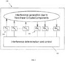
- the wireless device 100 may comprise radio devices such as transceivers and/or receivers 108 and transmitters 106 for receiving and transmitting signals via links between the wireless device 100 and other communication devices.
- the wireless device 100 comprises a plurality of transmitters 106 Tx 1 -Tx N equal to N, where N is greater than 1.
- the wireless device 100 also comprises one or more receivers 108 R X1 -R XM equal to M, where M is greater than zero.
- “transmitters Tx N " will herein refer collectively to transmitters 106 Tx 1 -Tx N , where a "transmitter Tx" may refer to any one of the transmitters 106 Tx 1 -Tx N .
- receivers 108 Rx 1 -Rx M will herein refer collectively to receivers 108 Rx 1 -Rx M , where a “receiver Rx” may refer to any one of the receivers 108 Rx 1 -Rx M .
- the wireless device 100 may utilize at least one transmitter 106 (e.g., Tx 1 ) and receiver 108 (e.g., Rx 1 ) to simultaneously transmit and receive data.
- the wireless device 100 may also utilize at least two transmitters 106 (e.g., Tx 1 and Tx 2 ) to simultaneously transmit signals at different radio carrier frequencies.
- the wireless device 100 may be configured to vary the power level of one or more transmitters 106 Tx N to reduce and/or prevent the generation of self-interference during simultaneous transmissions. Referring briefly to FIG. 2 , an example of interference generation will be described.
- a signal 200 transmitted from a first transmitter Tx m and a signal 202 transmitted from a second transmitter Tx n may couple to a non-linear circuit and/or component 204. As indicated in boxes 206 and 208, such coupling may occur via conductive coupling, radiative coupling, or a combination thereof.
- an output 210 of the non-linear circuit and/or component 204 may generate an interference signal 212 in one or more different frequencies than the frequencies of the two transmit signals 200 and 202.
- This interference signal 212 may couple to a path of an active receiver Rx k (e.g., via conductive and/or radiative coupling), and therefore, potentially degrade its performance.
- the interference signal 212 may couple to one or more receiver paths and potentially degrade the performance of each corresponding receiver.
- the wireless device 100 may comprise a control unit 102 for determining and controlling interference.
- the control unit 102 may be implemented via any suitable software, hardware, firmware, or combinations thereof.
- the control unit 102 may comprise or be operatively connected to a database 104, which may be configured to store instructions executable by the control unit 102 to control various operating functions of the wireless device 100.
- the database 104 is communicatively linked to the plurality of transmitters 106 Tx N and receivers 108 Rx M , each of which may be configured to populate the database 104 with various types of data.
- data may comprise operation carrier frequencies, signal characteristics (e.g., signal strength levels), modes of operation, performance figures for receptions and transmissions (e.g., signal quality indicators), etc.
- the control unit 102 may be communicatively linked to one or more sensors associated with the wireless device 100.
- the wireless device 100 may include sensors 120 for monitoring operating conditions such as temperatures corresponding to the transmitters Tx N , receivers Rx, RF/microwave circuits, etc.
- one or more sensors may be integrated with various non-linear RF/microwave components 130.
- the wireless device 100 may further comprise an RF sensor to monitor various RF signals over a wide range of frequencies without the requirement to demodulate and decode the underlying signals.
- a high power detector (HDET) can be placed on transmitter path to monitor the output power of that specific TX chain.
- HDET high power detector
- the control unit 102 may be configured to periodically obtain readings of a circuit board temperature in order to compensate for variations in temperature.
- One or more temperature sensors may be positioned to measure the temperature at one or more portions of the wireless device that may impact a signal quality and interference generation, which may include integrated, for example, chips within the wireless device, a radio frequency (RF)/microwave circuit area of the wireless device, and the transmitters 106 and receivers 108.
- RF radio frequency
- the database 104 may store previously captured and pre-programmed information, which the control unit 102 may use to create linear and non-linear self-interference models and estimate interference levels. For instance, prior to enabling a simultaneous transmission involving multiple radio devices, the control unit 102 may use such information to estimate the level of impact that interference may have on an active receiver 108. The control unit 102 may also perform an initial evaluation to calculate a maximum amount of power allowed for each active transmitter 106.
- radio devices may herein refer to one or more transmitters 106 Tx N and receivers 108 Rx M , and/or transceivers or like devices comprising circuitry for transmitting and receiving data.
- each radio device may comprise suitable circuitry for modulating/demodulating data (e.g., audio or voice) bits into a format that is compatible with a particular communication standard utilized by the radio devices.
- wireless communication standards e.g., IEEE 802.11, Bluetooth, advanced mobile phone services (AMPS), digital AMPS, global system for mobile communications (GSM), code division multiple access (CDMA), local multi-point distribution systems (LMDS), multi- channel-multi-point distribution systems (MMDS), and/or variations thereof
- GSM global system for mobile communications
- CDMA code division multiple access
- LMDS local multi-point distribution systems
- MMDS multi- channel-multi-point distribution systems
- the control unit 102 may use static and dynamic information to control the operation of transmitters 106 and receivers 108. During a transmission, for example, the control unit 102 may dynamically monitor the active receivers 108 for variances in reception quality. Thus, if a variance causes the quality of a reception signal to drop below a predetermined threshold, the control unit 102 may adjust power constraints such as the maximum allowable power level for each active transmitter 106. Furthermore, the control unit 102 may employ artificial intelligence algorithms, machine learning algorithms, adaptive control algorithms, self-optimization algorithms, and/or other suitable algorithms to dynamically fine tune certain aspects of the interference control model.
- control unit 102 may implement a technique referred to herein as, "Joint System Selection/Reselection.” In a second implementation, the control unit 102 may implement a technique referred to herein as, “Interference-Aware Handover.” In a third implementation, the control unit 102 may implement a technique referred to herein as, “Dynamic Power Limiting.” These and other implementations are described in further detail below.
- the wireless device 100 may be configured to search for and select or reselect a network for service acquisition.
- the wireless device 100 may select a network according to any suitable manner. For instance, the wireless device 100 may reference a list of networks stored in the database 104 and attempt to access the most preferred or prioritized network. Such a list may also include identifiers for each network/system listed, and acquisition parameters including band, frequency, and mode for the listed network/systems.
- the list of networks may be periodically updated such as by an external source (e.g., the wireless device's service provider), through wireless downloads, or through any suitable data transfer scheme.
- the wireless device 100 may select a network that is determined to provide the highest quality of service (QoS), enable the wireless device 100 to consume the least amount of power, generate the least amount of interference, etc.
- QoS quality of service
- the wireless device 100 may make such determinations based on signal strength characteristics such as the signal to interference ratio (SIR) or signal to noise ratio (SNR) of cells.
- SIR signal to interference ratio
- SNR signal to noise ratio
- Other factors that the wireless device 100 may take into account include a preferred Radio Access Technology (RAT), frequency band, etc.
- RAT Radio Access Technology
- the wireless device 100 may scan frequencies in some or all bands of each RAT to determine which frequencies carry physical channels.
- the wireless device 100 may support various modes of operations. For each supported mode, the wireless device 100 may scan different systems, RATs, frequency bands, etc. Moreover, the wireless device 100 may scan frequency bands based on a preferred or prioritized list of channels, and populate the database 104 with a list of available physical channels and corresponding signal qualities. In sum, the wireless device 100 may select networks using various types of information such as that described above.
- the wireless device 100 may perform a selection/reselection procedure that may be optimal for a particular system, but that may not be optimal for combined operating systems. For example, the combination of two modes/channels may cause serious interference in a simultaneous transmission mode. To reduce or prevent such interference, a Joint System Selection/Reselection technique according to the present disclosure may be used, where the control unit 102 selects or reselects a channel/system using static information and dynamic information.
- Static information may comprise configuration parameters such as preferred or prioritized modes of operation, spectral information such as shape and bandwidth, non-linearity characteristics of the transmitting and receiving components/circuits, factory calibration data, predefined data programming information, etc.
- Dynamic information may comprise information that is readily or instantly available such as operating bands and carrier frequencies of active transmitters 106 and receivers 108, predicted and/or initial target power levels for each transmitter 106, received signal strengths at each active receiver, channel quality estimates at each active receiver 108, physical conditions such as temperature, etc.
- Static information and dynamic information may be stored in the database 104, along with information associated with each radio device.
- each radio device may be configured to report a list of available channels to the control unit 102.
- Each radio device may be further configured to report corresponding channel information such as received signal strength indicators (RSSI), signal quality levels, error rates associated with received signals, etc.
- RSSI received signal strength indicators
- the control unit 102 may determine the best channel/system for each radio device based on the reported information, as well as information stored in the database 104, e.g., hardware linearity information, historical data, etc. In making this determination, the control unit 102 may employ a selection algorithm designed to achieve optimal system performance with minimal interference.
- the selection algorithm may use static and dynamic information to calculate an estimated level of interference generation for a simultaneous transmission. Based on the estimated interference levels, the control unit 102 may determine which selection of frequency bands/channels would result in the least amount of interference using the channels/systems available. The control unit 102 may then send the channel/system selection results to the corresponding radio devices. Accordingly, the control unit 102 may utilize the Joint System Selection/Reselection technique to select a channel/system for a given radio device based not only on its own selection standards/preferences, but also based upon those for all of the radio devices.
- Radio conditions may be determined using various parameters such as signal strength, path loss, propagation delay, received reference symbol power, and other signal quality parameters known to one of skill in the art. Based on such parameters, the control unit 102 - or other suitable component(s) associated with the wireless device 100 - may determine that the quality of the radio conditions for an existing communication session has deteriorated such that the session might need to be handed over to a different cell or network. Several nearby cells might be available to receive the handoff, and several different channels/frequency bands/RATs might be available in each of the cells.
- each radio device may perform a handover based on its own measurement report, and perhaps with assistance from a network.
- This handover procedure may not be optimal because self-interference resulting from simultaneous transmissions might be higher than as determined by a given radio device without simultaneous transmission, which was the case during the measurement activity required for handover. For instance, when a radio device performs a channel measurement, there is no active or real-time transmission in the corresponding TX band, and therefore, there is no simultaneous transmission occurring at such time.
- an Interference-Aware Handover technique may be used such that when handover events are triggered, each radio device may report channel measurement information such as channel quality indicators (CQIs) to the control unit 102.
- CQIs channel quality indicators
- the control unit 102 may estimate the potential interference that might result during a simultaneous transmission involving two or more radio devices.
- the control unit 102 may use estimated interference levels to modify or update the reported channel quality information, which may be stored in the database 104.
- the control unit 102 may send modified channel quality information to a corresponding radio device and network component (e.g., base node, enhanced based node (eNB), access point, etc.) so that an optimal system may be selected for the handover.
- a corresponding radio device and network component e.g., base node, enhanced based node (eNB), access point, etc.
- the control unit 102 may take into account the capabilities of each radio device in order to select a system determined to result in the least amount of interference during a simultaneous transmission between multiple radio devices.
- the control unit 102 may implement a Dynamic Power Limiting technique to limit the maximum power output of one or more radio devices to an acceptable level so as to reduce interference during a simultaneous transmission.
- This technique may be implemented in firmware, hardware, software, or any combination thereof.
- signal quality indicators such as a received signal strength indication (RSSI) from a radio device of high priority may be used to predict its transmit power.
- RSSI received signal strength indication
- a radio device may be defined to be of lower or higher priority according to any suitable criteria, e.g., preferred operating mode, dynamic range, etc.
- the transmit power of a high priority radio device may be predicted based on dynamic information gleaned from parameters such as channel quality and RSSI, which may depend upon factors such as path loss, error rates, shadowing and fading of the radio link between a corresponding transmitter and receiver, etc.
- fading margin may be added to the predicted transmit power, where the added fading margin may be based on channel statistics derived from RSSI data. (Fading of the signal can occur randomly in the radio propagation. When the signal is faded, the received signal strength at the receiver end may drop below the acceptable level. In order to overcome this phenomenon, the signal may be transmitted at a higher power than the average power level. This is referred to as fading margin.)
- the control unit 102 may predict the transmit power of the high priority radio device. In another aspect, the predicted transmit power may be made by another component associated with the wireless device 100, in which case the prediction result will be sent to the control unit 102. In either aspect, the control unit 102 may use the predicted transmit power of the high priority radio device to estimate an interference level for a given combination of frequencies/Bandwidth/IRAT. As such, the control unit 102 can set a maximum transmit power for at least one radio device of lower priority. For instance, the control unit 102 may be configured to set the maximum transmit power of the radio device of lower priority such that during a simultaneous transmission, the low priority radio device may transmit at the highest acceptable power level, while preventing or limiting interference generation at or below an acceptable level. During the simultaneous transmission, the control unit 102 may be further configured to periodically update the maximum transmit power settings for the low priority radio device based on real-time information.
- the maximum transmit power of a low priority radio device may be limited based on a predicted transmission power, which is usually lower than the maximum transmit power (e.g., as used in a normal power limiting case).
- the predicted transmit power can help sustain channel fading and achieve desired performance levels, even in spite of software control delays.
- transmit powers may be predicted using transceiver transmit control signals, which may include pulse duration modulation (PDM), control information such as transmit signal strength indicators (TSSI), and power amplifier (PA) gain control information, etc.
- PDM pulse duration modulation
- TSSI transmit signal strength indicators
- PA power amplifier
- the combination of such control information with selected fading margin may be dynamically fed to the control unit 102.
- the control unit 102 may determine the maximum transmit power for a low priority radio device (e.g., using hardware logic circuitry), and set the transmitting portion of the low priority radio device accordingly.
- FIG. 4 illustrates an exemplary embodiment of a Joint System Selection/Reselection method 400 for interference control.
- the Joint System Selection/Reselection method 400 may be implemented on a wireless communication device (e.g., wireless device 100).
- the Joint System Selection/Reselection method 400 may begin at block 402 where, for each supported mode, the wireless communication device may scan different systems frequency bands based on a preferred channel list, and build a list of available physical channels with corresponding signal qualities.
- each radio may report the available channel list to an Interference Control Unit (e.g., Interference Control Unit 102).
- the Interference Control Unit selects the best system/channel for each radio based on information provided by each radio and on hardware linearity information from a database (e.g., database 104).
- the Interference Control Unit sends the recommended system selection/reselection result to the system selection/reselection module of each individual radio.
- the method 400 may then end.
- FIG. 5 illustrates an embodiment of a method 500 for interference aware handover.
- the method 500 may be implemented on a wireless communication device (e.g., wireless device 100).
- the method 500 may begin at block 502 where the wireless communication device may detect an inferior channel condition for an active radio triggering handover.
- the channel measurement information is sent to the Interference Control Unit (e.g., Interference Control Unit 102).
- the Interference Control Unit estimates the potential interference based on a simultaneous transmission scenario.
- the Interference Control Unit generates modified channel quality information using the estimated potential interference.
- the modified channel quality information is sent to the network and used for a handover decision.
- the method 500 may then end.
- FIG. 6 illustrates an embodiment of a method 600 for dynamic power limiting.
- the method 600 may be implemented on a wireless communication device (e.g., wireless device 100).
- the method 600 may begin at block 602 where the wireless communication device may determine the received signal quality of a high priority radio.
- the wireless communication device may predict the transmission power of the higher priority radio.
- the predicted transmission power of the higher priority radio may be based on the channel quality (e.g., the Received Signal Strength Indication (RSSI)) and may add the fading margin that is based on the channel statistics derived from the RSSI data.
- the interference Control Unit or some other component within the wireless communication device may determine a maximum allowable power for the lower priority radio using the predicted power of the higher priority radio.
- the Interference Control Unit may periodically update the maximum power setting for the low priority radio to be used during simultaneous transmission based on updated dynamically determined RSSI and/or other information. The method 600 may then end.
- RSSI Received Signal Strength Indication
- R R l + k ⁇ (R u - R l ), wherein k is a variable ranging from 1 percent to 100 percent with a 1 percent increment, i.e., k is 1 percent, 2 percent, 3 percent, 4 percent, 7 percent, ..., 70 percent, 71 percent, 72 percent, ..., 97 percent, 96 percent, 97 percent, 98 percent, 99 percent, or 100 percent.
- any numerical range defined by two R numbers as defined in the above is also specifically disclosed.
Landscapes
- Engineering & Computer Science (AREA)
- Computer Networks & Wireless Communication (AREA)
- Signal Processing (AREA)
- Physics & Mathematics (AREA)
- Electromagnetism (AREA)
- Mobile Radio Communication Systems (AREA)
Claims (11)
- Appareil sans fil (100) comprenant :une première radio (106, 108) ayant une première priorité, la première radio comprenant un premier émetteur et un premier récepteur ;une seconde radio (106, 108) ayant une seconde priorité inférieure à la première priorité, la seconde radio comprenant un second émetteur et un second récepteur,où les première et seconde radios sont configurées pour une transmission simultanée ; etune unité de commande (102) configurée pour déterminer une qualité de signal reçu de la première radio ; prédire la puissance d'émission de la première radio sur la base de la qualité de signal reçu et d'autres informations dynamiques et statiques, où la puissance d'émission prévue de la première radio est inférieure ou égale à un niveau de puissance maximal disponible pour la première radio ; et déterminer une puissance maximale admissible de la seconde radio en utilisant la puissance prévue de la première radio pour contrôler la génération des interférences pendant la transmission simultanée.
- Appareil sans fil selon la revendication 1, dans lequel les informations déterminées dynamiquement comprennent au moins l'un des éléments suivants : une bande de fonctionnement ;
une fréquence porteuse des fréquences actives des première et seconde radios ;
un niveau de puissance cible courant pour au moins l'une des première et seconde radios ;
un niveau de puissance cible initial pour au moins l'une des première et seconde radios ;
une intensité de signal reçu pour au moins l'une des première et seconde radios ;
une estimation de la qualité des canaux pour au moins l'une des première et seconde radios ; ou
une priorité par rapport à un mode de fonctionnement spécifié. - Appareil sans fil selon la revendication 1, dans lequel les informations déterminées dynamiquement comprennent des informations spectrales qui sont les caractéristiques de signaux physiques des signaux d'émission et de réception souhaités, des signaux de canal ajustés et des interférences potentielles générées en interne ou couplées en externe.
- Appareil sans fil selon la revendication 1, dans lequel les informations déterminées dynamiquement comprennent une largeur de bande de canal ou une variation de qualité de réception pour les première et seconde radios.
- Appareil sans fil selon la revendication 1, comprenant en outre :au moins un capteur de température pour mesurer la température d'au moins une partie du dispositif sans fil qui peut influer sur la qualité du signal et la génération des interférences,où les informations déterminées dynamiquement comprennent la température.
- Appareil sans fil selon la revendication 5, dans lequel la partie comprend au moins l'un du premier émetteur et du second émetteur.
- Appareil sans fil selon la revendication 5, dans lequel la partie comprend au moins l'un du premier récepteur et du second récepteur.
- Appareil sans fil selon la revendication 5, dans lequel la partie comprend une zone de circuit radiofréquence (RF)/micro-ondes du dispositif sans fil.
- Procédé (600) de limitation dynamique de puissance au cours de la transmission simultanée d'une première radio et d'une seconde radio sur un dispositif sans fil, la première radio comprenant un premier émetteur et un premier récepteur, et la seconde radio comprenant un second émetteur et un second récepteur, le procédé comprenant les étapes suivantes :déterminer (602) une qualité de signal reçu de la première radio ayant une première priorité ;prédire (604) la puissance d'émission de la première radio sur la base de la qualité du signal reçu et d'autres informations dynamiques et statiques, où la puissance d'émission prévue de la première radio est inférieure ou égale à un niveau de puissance maximum disponible pour la première radio ; etdéterminer (606) une puissance maximale admissible de la seconde radio ayant une seconde priorité en utilisant la puissance prévue de la première radio pour contrôler la génération des interférences, où la seconde priorité est inférieure à la première priorité.
- Procédé selon la revendication 9, dans lequel des informations statiques comprennent une marge d'évanouissement, où la marge d'évanouissement est basée sur des statistiques de canal dérivées d'une indication d'intensité de signal reçu (RSSI) de la première radio.
- Procédé selon la revendication 9, dans lequel la puissance d'émission prévue de la première radio est en outre basée sur des informations déterminées dynamiquement qui comprennent au moins l'un des éléments suivants : une bande de fonctionnement, la fréquence porteuse des dispositifs actifs parmi les premier et second émetteurs et les premier et second récepteurs, les niveaux de puissance cibles courants pour chacun des premier et second émetteurs, les niveaux de puissance cibles initiaux pour chacun des premier et second émetteurs, les intensités des signaux reçus pour chacun des premier et second récepteurs et une estimation de qualité des canaux pour chacun des premier et second récepteurs.
Applications Claiming Priority (3)
| Application Number | Priority Date | Filing Date | Title |
|---|---|---|---|
| US42200510P | 2010-12-10 | 2010-12-10 | |
| US13/313,843 US20120149412A1 (en) | 2010-12-10 | 2011-12-07 | System and Method for Interference Control in Simultaneous Transmission Systems |
| PCT/CN2011/083830 WO2012075969A1 (fr) | 2010-12-10 | 2011-12-12 | Système et procédé pour contrôler des interférences dans des systèmes de transmission simultanée |
Publications (3)
| Publication Number | Publication Date |
|---|---|
| EP2633723A1 EP2633723A1 (fr) | 2013-09-04 |
| EP2633723A4 EP2633723A4 (fr) | 2013-12-25 |
| EP2633723B1 true EP2633723B1 (fr) | 2019-06-19 |
Family
ID=46199883
Family Applications (1)
| Application Number | Title | Priority Date | Filing Date |
|---|---|---|---|
| EP11846074.0A Not-in-force EP2633723B1 (fr) | 2010-12-10 | 2011-12-12 | Système et procédé pour contrôler des interférences dans des systèmes de transmission simultanée |
Country Status (4)
| Country | Link |
|---|---|
| US (1) | US20120149412A1 (fr) |
| EP (1) | EP2633723B1 (fr) |
| CN (1) | CN103262618A (fr) |
| WO (1) | WO2012075969A1 (fr) |
Families Citing this family (16)
| Publication number | Priority date | Publication date | Assignee | Title |
|---|---|---|---|---|
| CA2583273C (fr) * | 2004-10-13 | 2016-01-05 | Mcmaster University | Techniques d'analyse d'environnement operationnel pour systemes de communication sans fil |
| EP2826306A1 (fr) * | 2012-03-16 | 2015-01-21 | Sony Mobile Communications AB | Recherche de canaux sur la base d'informations de disponibilité de canaux |
| US9750028B2 (en) | 2012-10-11 | 2017-08-29 | Qualcomm Incorporated | Apparatus and methods for enhanced maximum power in multicarrier wireless communications |
| US10182404B2 (en) | 2013-03-06 | 2019-01-15 | Qualcomm Incorporated | Transmit power calibration for matching the coverage of different radio technologies on a common radio node |
| US10243678B2 (en) * | 2013-10-28 | 2019-03-26 | National Instruments Corporation | Linearization of radio frequency transceivers and test systems through dynamic extraction of complex nonlinear models thereof |
| US9167588B1 (en) * | 2014-04-15 | 2015-10-20 | Qualcomm Incorporated | Enhanced mobile standby performance during simultaneous dual-technology communication by avoiding interference scenarios |
| CN107211291B (zh) * | 2014-11-27 | 2020-12-01 | 缪国往 | 在移动网络中实现邻近服务的方法和装置 |
| KR20160085087A (ko) * | 2015-01-07 | 2016-07-15 | 삼성전자주식회사 | 무선 통신 장치 및 방법 |
| WO2016172925A1 (fr) * | 2015-04-30 | 2016-11-03 | Telefonaktiebolaget Lm Ericsson (Publ) | Procédés utilisés dans des nœuds radio et nœuds radio associés |
| CN107863973A (zh) * | 2016-09-22 | 2018-03-30 | 深圳市中兴微电子技术有限公司 | 一种功率定标方法和装置 |
| CN113541700B (zh) * | 2017-05-03 | 2022-09-30 | 弗吉尼亚科技知识产权有限公司 | 用无线电信号变换器学习无线电信号的方法、系统和装置 |
| US11026186B2 (en) * | 2017-10-27 | 2021-06-01 | Qualcomm Incorporated | Power control for concurrent reception |
| US10601471B1 (en) | 2018-08-29 | 2020-03-24 | Micron Technology, Inc. | Neuron calculator for artificial neural networks |
| CN113287275B (zh) * | 2018-10-19 | 2024-09-20 | 苹果公司 | 非正交多址接入混合自动重发请求 |
| GB202003404D0 (en) * | 2020-03-09 | 2020-04-22 | Nordic Semiconductor Asa | Radio transmitter apparatus with cryptographic engine |
| US11375463B2 (en) * | 2020-11-30 | 2022-06-28 | Silicon Laboratories Inc. | System, apparatus and method for dynamic transmit power determination |
Citations (1)
| Publication number | Priority date | Publication date | Assignee | Title |
|---|---|---|---|---|
| WO2010089281A1 (fr) * | 2009-02-05 | 2010-08-12 | Telefonaktiebolaget L M Ericsson (Publ) | Coexistence de plusieurs émetteurs-récepteurs de communication sans fil à proximité immédiate |
Family Cites Families (21)
| Publication number | Priority date | Publication date | Assignee | Title |
|---|---|---|---|---|
| US6771721B1 (en) * | 1997-06-20 | 2004-08-03 | Telefonaktiebolaget Lm Ericsson (Publ) | Method and apparatus for eliminating audio clicks in a radio receiver |
| US6735447B1 (en) * | 1999-12-08 | 2004-05-11 | Telefonaktiebolaget Lm Ericsson (Publ) | Transmission power control of a mobile station |
| US6553016B1 (en) * | 1999-12-20 | 2003-04-22 | Telfonaktiebolaget Lm Ericsson (Publ) | Downlink power control at soft handover |
| US6745018B1 (en) * | 2000-09-29 | 2004-06-01 | Intel Corporation | Active cancellation of a wireless coupled transmit signal |
| JP2005039765A (ja) * | 2003-06-25 | 2005-02-10 | Renesas Technology Corp | マルチモード型無線端末および無線送受信部 |
| US7486953B2 (en) * | 2003-11-26 | 2009-02-03 | Northrop Grumman Corporation | Method and system for soft handover |
| US10200094B2 (en) * | 2004-04-02 | 2019-02-05 | Rearden, Llc | Interference management, handoff, power control and link adaptation in distributed-input distributed-output (DIDO) communication systems |
| US20070214286A1 (en) * | 2005-11-10 | 2007-09-13 | Olympus Communication Technology Of America, Inc. | Network access control |
| US7966033B2 (en) * | 2006-01-05 | 2011-06-21 | Qualcomm Incorporated | Serving sector directed power control |
| US20090318087A1 (en) * | 2006-02-20 | 2009-12-24 | Mattila Heikki O | Method and Device for Preventing Interference at a Radio Receiver Device Caused by Several Radio Transmitter Devices |
| US8693950B2 (en) * | 2006-03-23 | 2014-04-08 | Broadcom Corporation | Method and system for transmit power control techniques to reduce mutual interference between coexistent wireless networks device |
| CN1937816A (zh) * | 2006-10-20 | 2007-03-28 | Ut斯达康通讯有限公司 | 一种双模移动通信终端 |
| CN101431821A (zh) * | 2007-11-08 | 2009-05-13 | 宇龙计算机通信科技(深圳)有限公司 | 一种多模通信终端及其通信处理方法 |
| US8086185B2 (en) * | 2007-11-21 | 2011-12-27 | Nokia Corporation | Qualify method for shielding of transceiver RF block |
| US8391796B2 (en) * | 2008-09-30 | 2013-03-05 | SpiderCloud Wirless, Inc. | Identifying and controlling interference from wireless terminals |
| US9048993B2 (en) * | 2009-12-18 | 2015-06-02 | Qualcomm Incorporated | Wireless communication channel blanking |
| CN101888252B (zh) * | 2010-04-20 | 2013-04-10 | 宁波成电泰克电子信息技术发展有限公司 | 一种提高rf系统中动态范围的方法及系统 |
| US8712467B2 (en) * | 2010-04-28 | 2014-04-29 | Plantronics, Inc. | Multiple RF band operation in mobile devices |
| US8588696B2 (en) * | 2010-06-04 | 2013-11-19 | Apple Inc. | Adaptive cellular power control |
| US8838046B2 (en) * | 2010-06-18 | 2014-09-16 | Mediatek Inc. | System and method of hybrid FDM/TDM coexistence interference avoidance |
| US9026055B2 (en) * | 2010-10-27 | 2015-05-05 | Intel Corporation | Power control technique to mitigate interference in multi-tier networks |
-
2011
- 2011-12-07 US US13/313,843 patent/US20120149412A1/en not_active Abandoned
- 2011-12-12 WO PCT/CN2011/083830 patent/WO2012075969A1/fr not_active Ceased
- 2011-12-12 CN CN2011800596226A patent/CN103262618A/zh active Pending
- 2011-12-12 EP EP11846074.0A patent/EP2633723B1/fr not_active Not-in-force
Patent Citations (1)
| Publication number | Priority date | Publication date | Assignee | Title |
|---|---|---|---|---|
| WO2010089281A1 (fr) * | 2009-02-05 | 2010-08-12 | Telefonaktiebolaget L M Ericsson (Publ) | Coexistence de plusieurs émetteurs-récepteurs de communication sans fil à proximité immédiate |
Also Published As
| Publication number | Publication date |
|---|---|
| CN103262618A (zh) | 2013-08-21 |
| WO2012075969A1 (fr) | 2012-06-14 |
| US20120149412A1 (en) | 2012-06-14 |
| EP2633723A1 (fr) | 2013-09-04 |
| EP2633723A4 (fr) | 2013-12-25 |
Similar Documents
| Publication | Publication Date | Title |
|---|---|---|
| EP2633723B1 (fr) | Système et procédé pour contrôler des interférences dans des systèmes de transmission simultanée | |
| US9807659B2 (en) | Signaling design to support in-device coexistence interference avoidance | |
| US10123281B2 (en) | Inter-network assisted power control for interference mitigation of D2D communications | |
| EP3345428B1 (fr) | Performance de connexion améliorée dans des scénarios de déséquilibre ul/dl | |
| EP2761912B1 (fr) | Interférences inter-système dans des systèmes de communication | |
| US8396003B2 (en) | Control of radio process | |
| EP2321994B1 (fr) | Procédure de transfert basée sur la qualité entre cellules co-localisées | |
| KR101561757B1 (ko) | 모바일 통신 디바이스 및 시스템 | |
| EP2883405B1 (fr) | Appareil et procédés pour une accumulation de brouillage | |
| US8914055B2 (en) | Dynamic resource selection to reduce interference that results from direct device to device communications | |
| AU2013353656B2 (en) | Handover in a soft cell network | |
| CN111800243A (zh) | 无线通信系统处置新无线电装置内共存问题的方法和设备 | |
| US20140301339A1 (en) | Non-Contiguous Carrier Aggregation | |
| KR102391269B1 (ko) | 무선 다중 액세스 방식들 간의 동적 스위칭 | |
| US8660086B2 (en) | Method and apparatus for admission control and forced handover in a multi-layer network configuration | |
| CN102595465A (zh) | 一种实现干扰信息上报的方法、系统及ue | |
| WO2011138268A1 (fr) | Appareil et procédé pour améliorer la mobilité d'agrégation des porteuses des technologies mises en œuvre pour les accès entre radios | |
| JP2007312433A (ja) | システム間境界閾値を決定する方法およびシステム | |
| WO2016163930A1 (fr) | Csma ayant un seuil de détection de porteuse adaptatif dans des réseaux laa | |
| US9655021B2 (en) | System and method for UE-specific offloading | |
| EP3285543B1 (fr) | Terminal multi-mode | |
| CN118828763B (zh) | 终端设备的探测周期配置方法、装置、设备和存储介质 | |
| WO2013026192A1 (fr) | Procédés et appareil pour fournir des informations de mesure |
Legal Events
| Date | Code | Title | Description |
|---|---|---|---|
| PUAI | Public reference made under article 153(3) epc to a published international application that has entered the european phase |
Free format text: ORIGINAL CODE: 0009012 |
|
| 17P | Request for examination filed |
Effective date: 20130531 |
|
| AK | Designated contracting states |
Kind code of ref document: A1 Designated state(s): AL AT BE BG CH CY CZ DE DK EE ES FI FR GB GR HR HU IE IS IT LI LT LU LV MC MK MT NL NO PL PT RO RS SE SI SK SM TR |
|
| A4 | Supplementary search report drawn up and despatched |
Effective date: 20131122 |
|
| RIC1 | Information provided on ipc code assigned before grant |
Ipc: H04B 17/00 20060101ALI20131118BHEP Ipc: H04B 1/52 20060101AFI20131118BHEP Ipc: H04W 52/36 20090101ALI20131118BHEP |
|
| DAX | Request for extension of the european patent (deleted) | ||
| STAA | Information on the status of an ep patent application or granted ep patent |
Free format text: STATUS: EXAMINATION IS IN PROGRESS |
|
| 17Q | First examination report despatched |
Effective date: 20170529 |
|
| REG | Reference to a national code |
Ref country code: DE Ref legal event code: R079 Ref document number: 602011059914 Country of ref document: DE Free format text: PREVIOUS MAIN CLASS: H04W0052000000 Ipc: H04B0001525000 |
|
| RIC1 | Information provided on ipc code assigned before grant |
Ipc: H04B 17/29 20130904ALI20181029BHEP Ipc: H04W 52/36 20090101ALI20181029BHEP Ipc: H04B 17/14 20130904ALI20181029BHEP Ipc: H04B 1/525 20130904AFI20181029BHEP |
|
| RIC1 | Information provided on ipc code assigned before grant |
Ipc: H04B 17/14 20150101ALI20181029BHEP Ipc: H04B 17/29 20150101ALI20181029BHEP Ipc: H04B 1/525 20150101AFI20181029BHEP Ipc: H04W 52/36 20090101ALI20181029BHEP |
|
| GRAP | Despatch of communication of intention to grant a patent |
Free format text: ORIGINAL CODE: EPIDOSNIGR1 |
|
| STAA | Information on the status of an ep patent application or granted ep patent |
Free format text: STATUS: GRANT OF PATENT IS INTENDED |
|
| INTG | Intention to grant announced |
Effective date: 20190108 |
|
| RIC1 | Information provided on ipc code assigned before grant |
Ipc: H04W 52/36 20090101ALI20181029BHEP Ipc: H04B 17/29 20150101ALI20181029BHEP Ipc: H04B 17/14 20150101ALI20181029BHEP Ipc: H04B 1/525 20150101AFI20181029BHEP |
|
| GRAS | Grant fee paid |
Free format text: ORIGINAL CODE: EPIDOSNIGR3 |
|
| GRAA | (expected) grant |
Free format text: ORIGINAL CODE: 0009210 |
|
| STAA | Information on the status of an ep patent application or granted ep patent |
Free format text: STATUS: THE PATENT HAS BEEN GRANTED |
|
| AK | Designated contracting states |
Kind code of ref document: B1 Designated state(s): AL AT BE BG CH CY CZ DE DK EE ES FI FR GB GR HR HU IE IS IT LI LT LU LV MC MK MT NL NO PL PT RO RS SE SI SK SM TR |
|
| REG | Reference to a national code |
Ref country code: GB Ref legal event code: FG4D |
|
| REG | Reference to a national code |
Ref country code: CH Ref legal event code: EP |
|
| REG | Reference to a national code |
Ref country code: IE Ref legal event code: FG4D |
|
| REG | Reference to a national code |
Ref country code: DE Ref legal event code: R096 Ref document number: 602011059914 Country of ref document: DE |
|
| REG | Reference to a national code |
Ref country code: AT Ref legal event code: REF Ref document number: 1146798 Country of ref document: AT Kind code of ref document: T Effective date: 20190715 |
|
| REG | Reference to a national code |
Ref country code: NL Ref legal event code: MP Effective date: 20190619 |
|
| PG25 | Lapsed in a contracting state [announced via postgrant information from national office to epo] |
Ref country code: FI Free format text: LAPSE BECAUSE OF FAILURE TO SUBMIT A TRANSLATION OF THE DESCRIPTION OR TO PAY THE FEE WITHIN THE PRESCRIBED TIME-LIMIT Effective date: 20190619 Ref country code: AL Free format text: LAPSE BECAUSE OF FAILURE TO SUBMIT A TRANSLATION OF THE DESCRIPTION OR TO PAY THE FEE WITHIN THE PRESCRIBED TIME-LIMIT Effective date: 20190619 Ref country code: SE Free format text: LAPSE BECAUSE OF FAILURE TO SUBMIT A TRANSLATION OF THE DESCRIPTION OR TO PAY THE FEE WITHIN THE PRESCRIBED TIME-LIMIT Effective date: 20190619 Ref country code: NO Free format text: LAPSE BECAUSE OF FAILURE TO SUBMIT A TRANSLATION OF THE DESCRIPTION OR TO PAY THE FEE WITHIN THE PRESCRIBED TIME-LIMIT Effective date: 20190919 Ref country code: LT Free format text: LAPSE BECAUSE OF FAILURE TO SUBMIT A TRANSLATION OF THE DESCRIPTION OR TO PAY THE FEE WITHIN THE PRESCRIBED TIME-LIMIT Effective date: 20190619 Ref country code: HR Free format text: LAPSE BECAUSE OF FAILURE TO SUBMIT A TRANSLATION OF THE DESCRIPTION OR TO PAY THE FEE WITHIN THE PRESCRIBED TIME-LIMIT Effective date: 20190619 |
|
| REG | Reference to a national code |
Ref country code: LT Ref legal event code: MG4D |
|
| PG25 | Lapsed in a contracting state [announced via postgrant information from national office to epo] |
Ref country code: LV Free format text: LAPSE BECAUSE OF FAILURE TO SUBMIT A TRANSLATION OF THE DESCRIPTION OR TO PAY THE FEE WITHIN THE PRESCRIBED TIME-LIMIT Effective date: 20190619 Ref country code: GR Free format text: LAPSE BECAUSE OF FAILURE TO SUBMIT A TRANSLATION OF THE DESCRIPTION OR TO PAY THE FEE WITHIN THE PRESCRIBED TIME-LIMIT Effective date: 20190920 Ref country code: RS Free format text: LAPSE BECAUSE OF FAILURE TO SUBMIT A TRANSLATION OF THE DESCRIPTION OR TO PAY THE FEE WITHIN THE PRESCRIBED TIME-LIMIT Effective date: 20190619 Ref country code: BG Free format text: LAPSE BECAUSE OF FAILURE TO SUBMIT A TRANSLATION OF THE DESCRIPTION OR TO PAY THE FEE WITHIN THE PRESCRIBED TIME-LIMIT Effective date: 20190919 |
|
| REG | Reference to a national code |
Ref country code: AT Ref legal event code: MK05 Ref document number: 1146798 Country of ref document: AT Kind code of ref document: T Effective date: 20190619 |
|
| PG25 | Lapsed in a contracting state [announced via postgrant information from national office to epo] |
Ref country code: SK Free format text: LAPSE BECAUSE OF FAILURE TO SUBMIT A TRANSLATION OF THE DESCRIPTION OR TO PAY THE FEE WITHIN THE PRESCRIBED TIME-LIMIT Effective date: 20190619 Ref country code: PT Free format text: LAPSE BECAUSE OF FAILURE TO SUBMIT A TRANSLATION OF THE DESCRIPTION OR TO PAY THE FEE WITHIN THE PRESCRIBED TIME-LIMIT Effective date: 20191021 Ref country code: EE Free format text: LAPSE BECAUSE OF FAILURE TO SUBMIT A TRANSLATION OF THE DESCRIPTION OR TO PAY THE FEE WITHIN THE PRESCRIBED TIME-LIMIT Effective date: 20190619 Ref country code: AT Free format text: LAPSE BECAUSE OF FAILURE TO SUBMIT A TRANSLATION OF THE DESCRIPTION OR TO PAY THE FEE WITHIN THE PRESCRIBED TIME-LIMIT Effective date: 20190619 Ref country code: RO Free format text: LAPSE BECAUSE OF FAILURE TO SUBMIT A TRANSLATION OF THE DESCRIPTION OR TO PAY THE FEE WITHIN THE PRESCRIBED TIME-LIMIT Effective date: 20190619 Ref country code: NL Free format text: LAPSE BECAUSE OF FAILURE TO SUBMIT A TRANSLATION OF THE DESCRIPTION OR TO PAY THE FEE WITHIN THE PRESCRIBED TIME-LIMIT Effective date: 20190619 Ref country code: CZ Free format text: LAPSE BECAUSE OF FAILURE TO SUBMIT A TRANSLATION OF THE DESCRIPTION OR TO PAY THE FEE WITHIN THE PRESCRIBED TIME-LIMIT Effective date: 20190619 |
|
| PG25 | Lapsed in a contracting state [announced via postgrant information from national office to epo] |
Ref country code: ES Free format text: LAPSE BECAUSE OF FAILURE TO SUBMIT A TRANSLATION OF THE DESCRIPTION OR TO PAY THE FEE WITHIN THE PRESCRIBED TIME-LIMIT Effective date: 20190619 Ref country code: IS Free format text: LAPSE BECAUSE OF FAILURE TO SUBMIT A TRANSLATION OF THE DESCRIPTION OR TO PAY THE FEE WITHIN THE PRESCRIBED TIME-LIMIT Effective date: 20191019 Ref country code: SM Free format text: LAPSE BECAUSE OF FAILURE TO SUBMIT A TRANSLATION OF THE DESCRIPTION OR TO PAY THE FEE WITHIN THE PRESCRIBED TIME-LIMIT Effective date: 20190619 Ref country code: IT Free format text: LAPSE BECAUSE OF FAILURE TO SUBMIT A TRANSLATION OF THE DESCRIPTION OR TO PAY THE FEE WITHIN THE PRESCRIBED TIME-LIMIT Effective date: 20190619 |
|
| PG25 | Lapsed in a contracting state [announced via postgrant information from national office to epo] |
Ref country code: TR Free format text: LAPSE BECAUSE OF FAILURE TO SUBMIT A TRANSLATION OF THE DESCRIPTION OR TO PAY THE FEE WITHIN THE PRESCRIBED TIME-LIMIT Effective date: 20190619 |
|
| PG25 | Lapsed in a contracting state [announced via postgrant information from national office to epo] |
Ref country code: PL Free format text: LAPSE BECAUSE OF FAILURE TO SUBMIT A TRANSLATION OF THE DESCRIPTION OR TO PAY THE FEE WITHIN THE PRESCRIBED TIME-LIMIT Effective date: 20190619 Ref country code: DK Free format text: LAPSE BECAUSE OF FAILURE TO SUBMIT A TRANSLATION OF THE DESCRIPTION OR TO PAY THE FEE WITHIN THE PRESCRIBED TIME-LIMIT Effective date: 20190619 |
|
| PG25 | Lapsed in a contracting state [announced via postgrant information from national office to epo] |
Ref country code: IS Free format text: LAPSE BECAUSE OF FAILURE TO SUBMIT A TRANSLATION OF THE DESCRIPTION OR TO PAY THE FEE WITHIN THE PRESCRIBED TIME-LIMIT Effective date: 20200224 |
|
| REG | Reference to a national code |
Ref country code: DE Ref legal event code: R097 Ref document number: 602011059914 Country of ref document: DE |
|
| PLBE | No opposition filed within time limit |
Free format text: ORIGINAL CODE: 0009261 |
|
| STAA | Information on the status of an ep patent application or granted ep patent |
Free format text: STATUS: NO OPPOSITION FILED WITHIN TIME LIMIT |
|
| PG2D | Information on lapse in contracting state deleted |
Ref country code: IS |
|
| REG | Reference to a national code |
Ref country code: CH Ref legal event code: PL |
|
| 26N | No opposition filed |
Effective date: 20200603 |
|
| REG | Reference to a national code |
Ref country code: BE Ref legal event code: MM Effective date: 20191231 |
|
| PG25 | Lapsed in a contracting state [announced via postgrant information from national office to epo] |
Ref country code: MC Free format text: LAPSE BECAUSE OF FAILURE TO SUBMIT A TRANSLATION OF THE DESCRIPTION OR TO PAY THE FEE WITHIN THE PRESCRIBED TIME-LIMIT Effective date: 20190619 Ref country code: SI Free format text: LAPSE BECAUSE OF FAILURE TO SUBMIT A TRANSLATION OF THE DESCRIPTION OR TO PAY THE FEE WITHIN THE PRESCRIBED TIME-LIMIT Effective date: 20190619 |
|
| PG25 | Lapsed in a contracting state [announced via postgrant information from national office to epo] |
Ref country code: IE Free format text: LAPSE BECAUSE OF NON-PAYMENT OF DUE FEES Effective date: 20191212 Ref country code: LU Free format text: LAPSE BECAUSE OF NON-PAYMENT OF DUE FEES Effective date: 20191212 |
|
| PG25 | Lapsed in a contracting state [announced via postgrant information from national office to epo] |
Ref country code: LI Free format text: LAPSE BECAUSE OF NON-PAYMENT OF DUE FEES Effective date: 20191231 Ref country code: BE Free format text: LAPSE BECAUSE OF NON-PAYMENT OF DUE FEES Effective date: 20191231 Ref country code: CH Free format text: LAPSE BECAUSE OF NON-PAYMENT OF DUE FEES Effective date: 20191231 |
|
| PG25 | Lapsed in a contracting state [announced via postgrant information from national office to epo] |
Ref country code: CY Free format text: LAPSE BECAUSE OF FAILURE TO SUBMIT A TRANSLATION OF THE DESCRIPTION OR TO PAY THE FEE WITHIN THE PRESCRIBED TIME-LIMIT Effective date: 20190619 |
|
| PG25 | Lapsed in a contracting state [announced via postgrant information from national office to epo] |
Ref country code: HU Free format text: LAPSE BECAUSE OF FAILURE TO SUBMIT A TRANSLATION OF THE DESCRIPTION OR TO PAY THE FEE WITHIN THE PRESCRIBED TIME-LIMIT; INVALID AB INITIO Effective date: 20111212 Ref country code: MT Free format text: LAPSE BECAUSE OF FAILURE TO SUBMIT A TRANSLATION OF THE DESCRIPTION OR TO PAY THE FEE WITHIN THE PRESCRIBED TIME-LIMIT Effective date: 20190619 |
|
| PG25 | Lapsed in a contracting state [announced via postgrant information from national office to epo] |
Ref country code: MK Free format text: LAPSE BECAUSE OF FAILURE TO SUBMIT A TRANSLATION OF THE DESCRIPTION OR TO PAY THE FEE WITHIN THE PRESCRIBED TIME-LIMIT Effective date: 20190619 |
|
| PGFP | Annual fee paid to national office [announced via postgrant information from national office to epo] |
Ref country code: GB Payment date: 20231102 Year of fee payment: 13 |
|
| PGFP | Annual fee paid to national office [announced via postgrant information from national office to epo] |
Ref country code: FR Payment date: 20231108 Year of fee payment: 13 Ref country code: DE Payment date: 20231031 Year of fee payment: 13 |
|
| REG | Reference to a national code |
Ref country code: DE Ref legal event code: R119 Ref document number: 602011059914 Country of ref document: DE |
|
| GBPC | Gb: european patent ceased through non-payment of renewal fee |
Effective date: 20241212 |
|
| PG25 | Lapsed in a contracting state [announced via postgrant information from national office to epo] |
Ref country code: DE Free format text: LAPSE BECAUSE OF NON-PAYMENT OF DUE FEES Effective date: 20250701 |
|
| PG25 | Lapsed in a contracting state [announced via postgrant information from national office to epo] |
Ref country code: GB Free format text: LAPSE BECAUSE OF NON-PAYMENT OF DUE FEES Effective date: 20241212 |
|
| PG25 | Lapsed in a contracting state [announced via postgrant information from national office to epo] |
Ref country code: FR Free format text: LAPSE BECAUSE OF NON-PAYMENT OF DUE FEES Effective date: 20241231 |