EP2634029A1 - Hybridsystem, das ein pneumatisches Energiespeichersystem enthält und zur Ausstattung eines Kraftfahrzeugs bestimmt ist - Google Patents
Hybridsystem, das ein pneumatisches Energiespeichersystem enthält und zur Ausstattung eines Kraftfahrzeugs bestimmt ist Download PDFInfo
- Publication number
- EP2634029A1 EP2634029A1 EP13155560.9A EP13155560A EP2634029A1 EP 2634029 A1 EP2634029 A1 EP 2634029A1 EP 13155560 A EP13155560 A EP 13155560A EP 2634029 A1 EP2634029 A1 EP 2634029A1
- Authority
- EP
- European Patent Office
- Prior art keywords
- pressure
- tank
- hybrid system
- starter
- pmax
- Prior art date
- Legal status (The legal status is an assumption and is not a legal conclusion. Google has not performed a legal analysis and makes no representation as to the accuracy of the status listed.)
- Withdrawn
Links
Images

Classifications
-
- B—PERFORMING OPERATIONS; TRANSPORTING
- B60—VEHICLES IN GENERAL
- B60K—ARRANGEMENT OR MOUNTING OF PROPULSION UNITS OR OF TRANSMISSIONS IN VEHICLES; ARRANGEMENT OR MOUNTING OF PLURAL DIVERSE PRIME-MOVERS IN VEHICLES; AUXILIARY DRIVES FOR VEHICLES; INSTRUMENTATION OR DASHBOARDS FOR VEHICLES; ARRANGEMENTS IN CONNECTION WITH COOLING, AIR INTAKE, GAS EXHAUST OR FUEL SUPPLY OF PROPULSION UNITS IN VEHICLES
- B60K6/00—Arrangement or mounting of plural diverse prime-movers for mutual or common propulsion, e.g. hybrid propulsion systems comprising electric motors and internal combustion engines
- B60K6/08—Prime-movers comprising combustion engines and mechanical or fluid energy storing means
- B60K6/12—Prime-movers comprising combustion engines and mechanical or fluid energy storing means by means of a chargeable fluidic accumulator
-
- F—MECHANICAL ENGINEERING; LIGHTING; HEATING; WEAPONS; BLASTING
- F02—COMBUSTION ENGINES; HOT-GAS OR COMBUSTION-PRODUCT ENGINE PLANTS
- F02B—INTERNAL-COMBUSTION PISTON ENGINES; COMBUSTION ENGINES IN GENERAL
- F02B21/00—Engines characterised by air-storage chambers
-
- B—PERFORMING OPERATIONS; TRANSPORTING
- B60—VEHICLES IN GENERAL
- B60K—ARRANGEMENT OR MOUNTING OF PROPULSION UNITS OR OF TRANSMISSIONS IN VEHICLES; ARRANGEMENT OR MOUNTING OF PLURAL DIVERSE PRIME-MOVERS IN VEHICLES; AUXILIARY DRIVES FOR VEHICLES; INSTRUMENTATION OR DASHBOARDS FOR VEHICLES; ARRANGEMENTS IN CONNECTION WITH COOLING, AIR INTAKE, GAS EXHAUST OR FUEL SUPPLY OF PROPULSION UNITS IN VEHICLES
- B60K6/00—Arrangement or mounting of plural diverse prime-movers for mutual or common propulsion, e.g. hybrid propulsion systems comprising electric motors and internal combustion engines
- B60K6/08—Prime-movers comprising combustion engines and mechanical or fluid energy storing means
- B60K6/12—Prime-movers comprising combustion engines and mechanical or fluid energy storing means by means of a chargeable fluidic accumulator
- B60K2006/123—Prime-movers comprising combustion engines and mechanical or fluid energy storing means by means of a chargeable fluidic accumulator for driving pneumatic motors
-
- B—PERFORMING OPERATIONS; TRANSPORTING
- B60—VEHICLES IN GENERAL
- B60Y—INDEXING SCHEME RELATING TO ASPECTS CROSS-CUTTING VEHICLE TECHNOLOGY
- B60Y2400/00—Special features of vehicle units
- B60Y2400/15—Pneumatic energy storages, e.g. pressure air tanks
-
- Y—GENERAL TAGGING OF NEW TECHNOLOGICAL DEVELOPMENTS; GENERAL TAGGING OF CROSS-SECTIONAL TECHNOLOGIES SPANNING OVER SEVERAL SECTIONS OF THE IPC; TECHNICAL SUBJECTS COVERED BY FORMER USPC CROSS-REFERENCE ART COLLECTIONS [XRACs] AND DIGESTS
- Y02—TECHNOLOGIES OR APPLICATIONS FOR MITIGATION OR ADAPTATION AGAINST CLIMATE CHANGE
- Y02T—CLIMATE CHANGE MITIGATION TECHNOLOGIES RELATED TO TRANSPORTATION
- Y02T10/00—Road transport of goods or passengers
- Y02T10/60—Other road transportation technologies with climate change mitigation effect
- Y02T10/62—Hybrid vehicles
Definitions
- the invention relates to the field of arrangements or assemblies of several different primary engines for reciprocal or common propulsion of a motor vehicle. It relates to a hybrid system comprising a pneumatic energy storage system. It also relates to a method for implementing such a hybrid system.
- a motor vehicle is likely to be equipped with a hybrid system to provide for its displacement.
- the hybrid system includes a heat engine and a pneumatic energy storage system.
- the pneumatic energy storage system is used to deliver a complementary energy to that delivered by the heat engine.
- the heat engine converts the kinetic energy of the motor vehicle into compressed air which is stored inside a constituent air tank of the pneumatic energy storage system. When necessary, the stored pneumatic energy is converted into mechanical energy that is transmitted to a wheel set of the motor vehicle, which causes or participates in the movement of the vehicle.
- the device includes a high-pressure fluid accumulator at a high pressure, a first low-pressure fluid accumulator at a low pressure, and a second low-pressure fluid accumulator at a low pressure.
- the fluid consists of a liquid, such as oil.
- the tanks are connected in parallel with each other.
- Said device also comprises a hydraulic motor pump which is in connection with a wheel set of the motor vehicle. The hydraulic motor pump is adapted to pump the fluid from the first low pressure accumulator and the second low pressure accumulator to the high pressure accumulator when the hydraulic motor pump is driven into pump mode.
- the hydraulic motor pump is also able to return the fluid to the first and second low-pressure accumulators when the hydraulic motor pump is used in motor mode.
- hydraulic energy is stored inside the tanks, such hydraulic energy being for example reused during an acceleration phase of the motor vehicle, being restored to the wheel train of the motor vehicle.
- the hydraulic energy storage system of the document EP 1,470,014 does not solve the problems faced by today's hybrid systems. Indeed, it appears that it is necessary to have a compressed air at very high pressure, of the order of 20 bars for example, inside the high-pressure tank to generate a satisfactory motor torque. Indeed, the compressed air contained inside the high-pressure tank decreases in pressure during phases of use of the pneumatic energy from the high-pressure tank. It is then necessary to wait for full filling of the high-pressure tank with compressed air before an efficient engine torque can be generated. Such waiting time compromises an interest of current hybrid systems, especially in the case where the motor vehicle does not perform rolling steps for a satisfactory recovery of pneumatic energy.
- One possible solution would be to increase a volume of the air tank. However, insofar as it is preferred that the air tank be fixed close to the heat engine and without a flexible connection, such an increase in volume is pragmatically impossible.
- the object of the present invention is to propose a hybrid system which satisfactorily satisfies the aforementioned drawbacks and which makes it possible to satisfy a high engine torque demand, while having a reserve of compressed air at a very high pressure, in particular 20 bar. which is easy to use and rechargeable.
- a hybrid system of the present invention is a hybrid system for equipping a motor vehicle.
- the hybrid system includes a pneumatic energy storage system.
- the pneumatic energy storage system comprises at least a starter tank and a main tank.
- the starter tank and the main tank are advantageously mounted in series with each other.
- the starter tank is preferably interposed between the main tank and a constituent heat engine of the hybrid system.
- a pressure control system is advantageously interposed between the starter tank and the main tank.
- the pressure regulation system comprises a solenoid valve provided with a first pressure sensor fitted to the starter tank and a second pressure sensor fitted to the main tank.
- the pressure control system comprises a first non-return valve and a second valve which are arranged in parallel with one another.
- the method preferably comprises a third operating step in which the starter tank is worn from the maximum pressure up to the threshold pressure, the main reservoir being maintained at the maximum pressure.
- the method preferably comprises a fourth operating step in which the starter tank is brought from the threshold pressure to the maximum pressure, the main reservoir being maintained at the maximum pressure, the fourth operating step succeeding the third step of operation.
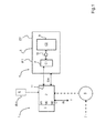
- a hybrid system 1 of the present invention equips a motor vehicle to allow a displacement of the latter.
- the hybrid system 1 comprises a heat engine 2 which is coupled to a gearbox 3.
- the heat engine 2 is an internal combustion engine that consumes fuel to allow the movement of the motor vehicle.
- the hybrid system 1 also comprises a pneumatic energy storage system 4 which comprises an air reserve 5 connected to the heat engine 2.
- the hybrid system 1 is configured to be implemented according to at least three modes of operation, of which:
- a first mode of operation M1 in which the hybrid system 1 converts a chemical energy Ech of the fuel contained inside a reservoir R into engine torque W which is transmitted to a wheel train T of motor vehicle,
- a mechanical energy Em such as a motor torque C or an engine speed
- a thermodynamic energy ET such that an increase of an air pressure P or an increase in an air temperature T, of a compressed air contained inside the air reserve 5
- the choice of the mode M1, M2, M3 to be activated among the modes M1, M2, M3 mentioned above is carried out by a calculator 6 which analyzes a request torque-engine 7 performed by a user of the motor vehicle. According to the amount of thermodynamic energy ET stored inside the air reserve 5 and the engine torque request 7, the computer 6 determines the mode M1, M2, M3 to activate and / or operates a mode change. M1, M2, M3.
- the motor torque W served in the third operating mode M3 is directly dependent on a value of the air pressure P of the compressed air stored inside the air reserve 5. More particularly, the torque motor W, which is generated and then serviced, is an increasing function of the air pressure P of the compressed air stored inside the air reserve 5.
- the air supply 5 comprises two air reservoirs 8, 9 placed in series with each other. More particularly, the air reserve 5 comprises a main reservoir 8 which is of a first capacitor C1 and a starter reservoir 9 which is of a second capacitor C2, lower than the first capacitor C1.
- the main tank 8 and the starter tank 9 are connected to each other by a pressure regulation system 10.
- the starter tank 9 is interposed between the heat engine 2 and the pressure control system 10.
- the pressure regulation system 10 is interposed between the starter tank 9 and the main tank 8.
- the starter tank 9 is connected to a valve 11 of the heat engine 1, so as to always have a satisfactory air pressure P inside the starter tank 9.
- the pressure regulation system 10 is intended to maintain an air pressure P which is satisfactory inside the starter tank 9, in particular by drawing air inside the main tank 8, during a operation of the heat engine 1 according to the third mode M3.
- the pressure regulating system 10 is also intended to recover a surplus of air pressure P of the compressed air coming from the main tank 8, during an operation according to the second mode M2.
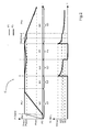
- FIG. 2 On the figure 2 , is shown a diagram of evolution of a first air pressure P1 contained inside the starter tank 9 and a second air pressure P2 contained inside the main tank 8 and a diagram of the evolution of the engine torque W during an operating cycle C of the hybrid system 1.
- the first operating step E1 comprises a first phase Ph1 and a second phase Ph2 which is consecutive to the first phase Ph1.
- the starter tank 8 fills with compressed air so that the first pressure P1 inside the latter changes from an initial pressure PO, of the order of 1 bar, until at a maximum pressure Pmax, for example of the order of 20 bars.
- the main reservoir 9 in turn contains compressed air at the initial pressure P0.
- the starting tank 8 is filled with compressed air until it reaches the maximum pressure Pmax while the main tank 9 is left at the initial pressure P0, which is notoriously equivalent to the pressure atmospheric.
- the starter tank 8 is maintained at the maximum pressure Pmax, while the main tank 9 fills with compressed air so that the second pressure P2 inside the latter evolves since the initial pressure P0 up to the maximum pressure Pmax.
- the second phase Ph2 thus constitutes a filling phase of the main tank 9 at the pressure Pmax.
- the first operating step E1 is an energy recovery step for the pneumatic energy storage system 4.
- the starter tank 8 and the main tank 9 are both held at the maximum pressure Pmax.
- the engine torque W generated by the pneumatic energy storage system 4 is zero. In other words, the motor vehicle moves only through the heat engine 2.
- the second operating step E2 is a pressure maintaining step for the pneumatic energy storage system 4, more particularly for the starter tank. 8 and the main tank 9.
- the first pressure P1 inside the starter tank 8 decreases from the maximum pressure Pmax to a threshold pressure Pseuil, for example of the order of 15 bars.
- the threshold pressure is between the maximum pressure Pmax and the initial pressure P0.
- the demand for engine torque 7 is small and / or short-lived.
- the pressure P1 thus remains greater than or equal to the threshold pressure Pseuil during the third operating step E3.
- the second pressure P2 remains equal to the maximum pressure Pmax.
- only the starter reservoir 8 is biased to provide a motor torque W the wheel train, the main reservoir 9 being maintained at constant pressure.
- the engine torque W generated by the pneumatic energy storage system 4 is non-zero.
- the engine torque W evolves from a maximum engine torque Wmax to a first engine torque W1.
- the third operating step E3 constitutes an operating step in a pneumatic motor for the motor vehicle that only biases the starter reservoir 8.
- the first capacitor C1 of the latter being lower than that of the main reservoir 9, the reservoir of start 8 is quickly refilled in the next step.
- the starter tank 8 is refilled with compressed air so that the first pressure P1 moves from the threshold pressure Pseuil to the maximum pressure Pmax.
- the main reservoir 9 is maintained at the maximum pressure Pmax.
- the engine torque W generated by the pneumatic energy storage system 4 is zero.
- the fourth operating step E4 constitutes an energy recovery step for the pneumatic energy storage system 4, more particularly for the starter tank 8.
- the fifth operating step E5 comprises a third phase Ph3, a fourth phase Ph4 which is consecutive to the third phase Ph3 and a fifth phase Ph5 which follows the fourth phase Ph4.
- the first pressure P1 inside the starter tank 8 decreases from the maximum pressure Pmax to the threshold pressure Pseuil.
- the second pressure P2 remains equal to the maximum pressure Pmax.
- the engine torque W generated by the pneumatic energy storage system 4 is non-zero.
- the engine torque W evolves from a maximum engine torque Wmax to a second engine torque W2, which is between the maximum engine torque Wmax and the first engine torque W1.
- the demand for engine torque 7 is important and / or long duration, the pressure P1 continues to fall and becomes lower than the threshold pressure Pseuil during the fourth phase Ph4.
- the first pressure P1 and the second pressure P2 evolve identically to one another from the threshold pressure Pseuil to a minimum pressure Pmin.
- the minimum pressure Pmin is between the threshold pressure Pseuil and the initial pressure P0.
- the motor torque W served decreases from the second motor torque W2 to a third motor torque W3, the latter possibly being zero in the case where the minimum pressure Pmin is equal to the initial pressure P0.
- the fifth operating step E5 constitutes a step of operation as a pneumatic motor for the motor vehicle that advantageously solicits the starter reservoir 8 and then the main reservoir 9.
- the pressure regulation system 10 illustrated on FIG. figure 3 which is an active pressure regulation system
- the latter comprises a solenoid valve 12 associated with a first pressure sensor 13 fitted to the starter tank 8 and a second pressure sensor 14 fitted to the main tank 9.
- the solenoid valve 12 is placed in the open position allowing an air passage between the starting tank 8 and the main tank 9 if and only if the first pressure P1 is greater than the maximum pressure Pmax or the second pressure P2 is greater than the first pressure P1 .
- the second variant embodiment of the pressure regulation system 10 illustrated on FIG. figure 4 is of the passive system type realized bydechanical means comprising a first non-return valve 16 which opens if the first pressure P1 is different from the second pressure P2 and a second valve 15 which opens if the first pressure is distinct from the maximum pressure Pmax.
- the first non-return valve 15 and the second valve 16 are connected in parallel with each other between the starting tank 8 and the main tank 9.
- the check valve 15 prevents the flow of fluid from the starter tank to the main tank. It allows the flow of fluid from the main tank to the starter tank when the pressure difference between the two tanks exceeds a first threshold.
- the other valve 15 allows the flow of fluid from the starter tank to the main tank when the pressure difference between the starter tank and the atmospheric pressure exceeds a second threshold.
Landscapes
- Engineering & Computer Science (AREA)
- Chemical & Material Sciences (AREA)
- Combustion & Propulsion (AREA)
- Mechanical Engineering (AREA)
- Transportation (AREA)
- General Engineering & Computer Science (AREA)
- Electric Propulsion And Braking For Vehicles (AREA)
- Hybrid Electric Vehicles (AREA)
Applications Claiming Priority (1)
| Application Number | Priority Date | Filing Date | Title |
|---|---|---|---|
| FR1251918A FR2987581B1 (fr) | 2012-03-02 | 2012-03-02 | Systeme hybride comprenant un systeme de stockage d'energie pneumatique et equipant un vehicule automobile |
Publications (1)
| Publication Number | Publication Date |
|---|---|
| EP2634029A1 true EP2634029A1 (de) | 2013-09-04 |
Family
ID=47683661
Family Applications (1)
| Application Number | Title | Priority Date | Filing Date |
|---|---|---|---|
| EP13155560.9A Withdrawn EP2634029A1 (de) | 2012-03-02 | 2013-02-18 | Hybridsystem, das ein pneumatisches Energiespeichersystem enthält und zur Ausstattung eines Kraftfahrzeugs bestimmt ist |
Country Status (2)
| Country | Link |
|---|---|
| EP (1) | EP2634029A1 (de) |
| FR (1) | FR2987581B1 (de) |
Cited By (1)
| Publication number | Priority date | Publication date | Assignee | Title |
|---|---|---|---|---|
| FR3014501A1 (fr) * | 2013-12-05 | 2015-06-12 | Peugeot Citroen Automobiles Sa | Procede d'aide au demarrage pour moteur hybride pneumatique |
Citations (8)
| Publication number | Priority date | Publication date | Assignee | Title |
|---|---|---|---|---|
| DE2422672A1 (de) * | 1974-05-10 | 1975-11-20 | Georg Ehses | Pressdruckluftmotor |
| US4478304A (en) * | 1980-08-14 | 1984-10-23 | Delano Tony M | Compressed air power engine |
| FR2754309A1 (fr) * | 1996-10-07 | 1998-04-10 | Guy Negre | Procede et dispositif de reacceleration pour vehicule equipe de compresseurs d'alimentation en air comprime haute pression pour moteur depollue ou depolluant |
| WO2004080744A1 (en) * | 2003-03-12 | 2004-09-23 | Thomas Tsoi-Hei Ma | Regenerative air hybrid engine |
| EP1470014A2 (de) | 2000-11-28 | 2004-10-27 | Shep Limited | Hydraulikenergiespeichersysteme |
| FR2905404A1 (fr) * | 2006-09-05 | 2008-03-07 | Mdi Motor Dev Internat Sa | Moteur a chambre active mono et/ou bi energie a air comprime et/ou energie additionnelle. |
| US7789181B1 (en) * | 2008-08-04 | 2010-09-07 | Michael Moses Schechter | Operating a plug-in air-hybrid vehicle |
| US20100314186A1 (en) * | 2008-01-16 | 2010-12-16 | Thomas Tsoi-Hei Ma | Air hybrid vehicle |
-
2012
- 2012-03-02 FR FR1251918A patent/FR2987581B1/fr not_active Expired - Fee Related
-
2013
- 2013-02-18 EP EP13155560.9A patent/EP2634029A1/de not_active Withdrawn
Patent Citations (8)
| Publication number | Priority date | Publication date | Assignee | Title |
|---|---|---|---|---|
| DE2422672A1 (de) * | 1974-05-10 | 1975-11-20 | Georg Ehses | Pressdruckluftmotor |
| US4478304A (en) * | 1980-08-14 | 1984-10-23 | Delano Tony M | Compressed air power engine |
| FR2754309A1 (fr) * | 1996-10-07 | 1998-04-10 | Guy Negre | Procede et dispositif de reacceleration pour vehicule equipe de compresseurs d'alimentation en air comprime haute pression pour moteur depollue ou depolluant |
| EP1470014A2 (de) | 2000-11-28 | 2004-10-27 | Shep Limited | Hydraulikenergiespeichersysteme |
| WO2004080744A1 (en) * | 2003-03-12 | 2004-09-23 | Thomas Tsoi-Hei Ma | Regenerative air hybrid engine |
| FR2905404A1 (fr) * | 2006-09-05 | 2008-03-07 | Mdi Motor Dev Internat Sa | Moteur a chambre active mono et/ou bi energie a air comprime et/ou energie additionnelle. |
| US20100314186A1 (en) * | 2008-01-16 | 2010-12-16 | Thomas Tsoi-Hei Ma | Air hybrid vehicle |
| US7789181B1 (en) * | 2008-08-04 | 2010-09-07 | Michael Moses Schechter | Operating a plug-in air-hybrid vehicle |
Cited By (2)
| Publication number | Priority date | Publication date | Assignee | Title |
|---|---|---|---|---|
| FR3014501A1 (fr) * | 2013-12-05 | 2015-06-12 | Peugeot Citroen Automobiles Sa | Procede d'aide au demarrage pour moteur hybride pneumatique |
| EP2886847A1 (de) * | 2013-12-05 | 2015-06-24 | Peugeot Citroën Automobiles Sa | Assistenzsystem zum Anlassen eines pneumatischen Hybridmotors |
Also Published As
| Publication number | Publication date |
|---|---|
| FR2987581B1 (fr) | 2015-03-13 |
| FR2987581A1 (fr) | 2013-09-06 |
Similar Documents
| Publication | Publication Date | Title |
|---|---|---|
| CA2692703C (fr) | Centrale hydraulique pour moteur a taux de compression variable | |
| EP2488380B1 (de) | Antriebssystem für ein hybridfahrzeug | |
| JP2010537105A (ja) | ブーストアシストシステム | |
| FR2978506A1 (fr) | Circuit de commande hydraulique | |
| WO2008003896A2 (fr) | Circuit hydraulique de recuperation d'energie | |
| FR2971741A1 (fr) | Chaine de traction d'un vehicule hybride utilisant une energie hydraulique | |
| EP2668054B1 (de) | Verfahren zur steuerung eines nachfüllmotors für den antrieb einer hydraulikpumpe | |
| FR2987581A1 (fr) | Systeme hybride comprenant un systeme de stockage d'energie pneumatique et equipant un vehicule automobile | |
| EP2445741B1 (de) | Verfahren und vorrichtung zum starten eines fahrzeugmotors | |
| EP3655640B1 (de) | Kraftwerk mit hilfskompressor in betrieb in der volllastphase | |
| EP2795714B1 (de) | Wärmespeichernde vorrichtung zum erwärmen einer fahrzeugbatterie | |
| EP2098425B1 (de) | Bremssysteme, die die Ausführung eines Stabilitäts- und Bewegungsbahnsteuerverfahrens erlauben | |
| US20140165965A1 (en) | Fuel supply system with accumulator | |
| EP4454046A1 (de) | Verfahren zur regelung eines drucks einer in einem kühlsystem zirkulierenden dielektrischen flüssigkeit | |
| EP3601056B1 (de) | Verfahren zur steuerung eines mehrfachmotorraums, steuerungssystem für einen mehrfachmotorraum und mehrfachmotorraum | |
| FR2928325A1 (fr) | Systeme de freinage avec control de stabilite et de trajectoire depourvu de pompe et muni d'un systeme de recuperation d'energie mecanique et procede de recuperation d'energie associe. | |
| EP2554819A1 (de) | Pneumatisch-thermischer Hybridmotor | |
| FR3054816A1 (fr) | Systeme d'actuation hydraulique d'un dispositif d'embrayage, notamment pour vehicule automobile | |
| WO2019238732A1 (fr) | Système de commande du groupe motopropulseur d'un véhicule hybride avec gestion de la surpression dans la rampe d'injection | |
| EP2739884B1 (de) | Vorrichtung zum hydraulischen steuern eines getriebes sowie entsprechendes verfahren und getriebe | |
| FR2989639A1 (fr) | Circuit d'air comprime pour un vehicule comprenant un materiau a changement de phase | |
| WO2015136170A1 (fr) | Systeme de freinage pour un vehicule hybride empechant le serrage des patins en mode recuperation d'energie | |
| JP2011512491A (ja) | 液圧ハイブリッド伝動遅延装置 | |
| FR3054001A1 (fr) | Systeme de commande hydraulique de soupapes pour moteur a combustion interne avec recuperation d'energie maximale | |
| FR2996876A1 (fr) | Moteur hybride pneumatique-thermique |
Legal Events
| Date | Code | Title | Description |
|---|---|---|---|
| PUAI | Public reference made under article 153(3) epc to a published international application that has entered the european phase |
Free format text: ORIGINAL CODE: 0009012 |
|
| AK | Designated contracting states |
Kind code of ref document: A1 Designated state(s): AL AT BE BG CH CY CZ DE DK EE ES FI FR GB GR HR HU IE IS IT LI LT LU LV MC MK MT NL NO PL PT RO RS SE SI SK SM TR |
|
| AX | Request for extension of the european patent |
Extension state: BA ME |
|
| 17P | Request for examination filed |
Effective date: 20140227 |
|
| RBV | Designated contracting states (corrected) |
Designated state(s): AL AT BE BG CH CY CZ DE DK EE ES FI FR GB GR HR HU IE IS IT LI LT LU LV MC MK MT NL NO PL PT RO RS SE SI SK SM TR |
|
| GRAP | Despatch of communication of intention to grant a patent |
Free format text: ORIGINAL CODE: EPIDOSNIGR1 |
|
| INTG | Intention to grant announced |
Effective date: 20151015 |
|
| STAA | Information on the status of an ep patent application or granted ep patent |
Free format text: STATUS: THE APPLICATION IS DEEMED TO BE WITHDRAWN |
|
| 18D | Application deemed to be withdrawn |
Effective date: 20160226 |