EP2634302A1 - Machine à laver avec unité de capteur - Google Patents
Machine à laver avec unité de capteur Download PDFInfo
- Publication number
- EP2634302A1 EP2634302A1 EP12157436.2A EP12157436A EP2634302A1 EP 2634302 A1 EP2634302 A1 EP 2634302A1 EP 12157436 A EP12157436 A EP 12157436A EP 2634302 A1 EP2634302 A1 EP 2634302A1
- Authority
- EP
- European Patent Office
- Prior art keywords
- gasket
- laundry machine
- machine according
- engagement
- tub
- Prior art date
- Legal status (The legal status is an assumption and is not a legal conclusion. Google has not performed a legal analysis and makes no representation as to the accuracy of the status listed.)
- Granted
Links
- 239000000523 sample Substances 0.000 claims abstract description 41
- 238000000034 method Methods 0.000 claims abstract description 22
- 230000008569 process Effects 0.000 claims abstract description 22
- 238000005406 washing Methods 0.000 claims abstract description 13
- 210000002105 tongue Anatomy 0.000 claims description 17
- 238000001035 drying Methods 0.000 claims description 9
- 230000000284 resting effect Effects 0.000 claims description 2
- XLYOFNOQVPJJNP-UHFFFAOYSA-N water Substances O XLYOFNOQVPJJNP-UHFFFAOYSA-N 0.000 description 13
- 210000003811 finger Anatomy 0.000 description 7
- 238000003860 storage Methods 0.000 description 7
- 238000007789 sealing Methods 0.000 description 4
- 239000000463 material Substances 0.000 description 3
- 238000004026 adhesive bonding Methods 0.000 description 2
- 238000003780 insertion Methods 0.000 description 2
- 230000037431 insertion Effects 0.000 description 2
- 238000003825 pressing Methods 0.000 description 2
- 230000001419 dependent effect Effects 0.000 description 1
- 230000000694 effects Effects 0.000 description 1
- 239000013536 elastomeric material Substances 0.000 description 1
- 238000009434 installation Methods 0.000 description 1
- 238000005304 joining Methods 0.000 description 1
- 238000005259 measurement Methods 0.000 description 1
- 230000007246 mechanism Effects 0.000 description 1
- 230000002265 prevention Effects 0.000 description 1
- 239000012858 resilient material Substances 0.000 description 1
- 239000003566 sealing material Substances 0.000 description 1
- 230000000087 stabilizing effect Effects 0.000 description 1
- 210000003813 thumb Anatomy 0.000 description 1
- 230000007704 transition Effects 0.000 description 1
- 238000003466 welding Methods 0.000 description 1
Images




Classifications
-
- D—TEXTILES; PAPER
- D06—TREATMENT OF TEXTILES OR THE LIKE; LAUNDERING; FLEXIBLE MATERIALS NOT OTHERWISE PROVIDED FOR
- D06F—LAUNDERING, DRYING, IRONING, PRESSING OR FOLDING TEXTILE ARTICLES
- D06F37/00—Details specific to washing machines covered by groups D06F21/00 - D06F25/00
- D06F37/26—Casings; Tubs
- D06F37/267—Tubs specially adapted for mounting thereto components or devices not provided for in preceding subgroups
-
- D—TEXTILES; PAPER
- D06—TREATMENT OF TEXTILES OR THE LIKE; LAUNDERING; FLEXIBLE MATERIALS NOT OTHERWISE PROVIDED FOR
- D06F—LAUNDERING, DRYING, IRONING, PRESSING OR FOLDING TEXTILE ARTICLES
- D06F2103/00—Parameters monitored or detected for the control of domestic laundry washing machines, washer-dryers or laundry dryers
- D06F2103/28—Air properties
- D06F2103/32—Temperature
Definitions
- the present invention relates to a laundry machine such as a washer/dryer or a washing machine.
- Laundry machines usually comprise one or more kinds of sensors for measuring or detecting process parameters of the laundry treatment process. Some of these sensors have sensor probes which have to be placed within an interior space of a laundry treatment container, e.g. a tub, in what the laundry treatment process is operated. Parameters of the laundry treatment process to be sensed may be for example the temperature or the concentration of moisture in the atmosphere of the laundry treatment container or the humidity of the laundry which is placed inside the container.
- the sensor probe can be arranged in a seat in a wall of the laundry treatment container, the detecting or measuring part of the sensor probe thereby within the interior space of the laundry treatment container and a part having electric or electronic connecting means on the outside of the laundry treatment container.
- the walls of the laundry treatment container usually comprise rib structures on the exterior side for structural enforcing the stability of the laundry treatment container.
- washing machines with drying function can have additional components such as condensers which have to be arranged or attached to the wall of the laundry treatment container on the exterior side.
- Such rib structures or additional parts complicate or impede the arrangement of the sensor probe in a desired position. Also the handling of the sensor probe in the mounting process is made difficult.
- the document EP 1 458 921 B1 discloses a water storage tub of a washing machine with a through hole, through which a fore end of a sensor is exposed to an inside of the water storage tub.
- the sensor has a mounting plate fastened to a fastening boss by fastening screws.
- a sealing material is applied between the mounting plate and the water storage for prevention of washing water leakage through the pass through hole for the sensor.
- said document describes a sensor that is fitted to the outside surface of the water storage tub firmly as the sensor is inserted into the pocket in the water storage tub from a fore end and a fixing plate seated on bosses is fastened with screws. Once the sensor is fitted thus, the sensor can receive the temperature of the water storage tub because the fore end of the sensor is in close contact with the pocket in the water storage tub. Thus, the washing water temperature can be measured indirectly.
- a laundry machine such as a washer/dryer or a washing machine, comprises:
- said at least one force receiving element is formed by at least one engagement recess and/or by at least one engagement tongue (or wing, or protrusion), preferably an alternating arrangement of at least two engagement recesses and at least two engagement tongues (or wing or protrusions), which can be gripped e.g. by a thumb and an index finger.
- the force receiving element(s) is/are adapted to fingers of a hand (of a worker) or to engagement elements of a tool so that for applying a rotational force fingers of a hand or engagement elements of a tool can engage in each force receiving element, in particular engagement recess and/or engagement tongue.
- the gasket has a contact portion and a clamping portion and, preferably, also an intermediate portion arranged between the contact portion and the clamping portion; the contact portion rests, in the mounted state, on a bearing surface of the gasket seat, preferably in plane contact, and the clamping portion is, in the mounted state, clamped in a through-hole of the gasket seat; if provided, the intermediate portion is, in the mounted state, arranged in a receiving space surrounded by a circumferential wall at a distance from the circumferential wall, wherein the bearing surface is preferably provided at the circumferential wall.
- This embodiment has good sealing characteristics.
- the force receiving element(s) is/are provided in an end face of the gasket.
- the end face is preferably arranged at the contact portion and, in the mounted state, on an opposite side opposite to the bearing surface of the gasket seat.
- the gasket can have a securing portion at the clamping portion being, in the mounted state, snapped into the through-hole for axially securing the gasket in one direction.
- each or the at least one engagement recess is open, i.e. has no side wall, at the outside or at the circumference of the end face or the contact portion.
- At least one pair or pairs of two engagement recesses and/or two engagement tongues (or wings or protrusions) are diametrically opposed which allows for a symmetric and easy gripping.
- steps are formed in the side walls of the engagement recesses and/or engagement tongues or wings or protrusions) for an improved gripping of the gasket.
- the force receiving element(s) is/are shaped like ring segments.
- said laundry machine comprises a tub unit having at least one tub wall and the at least one through hole of the gasket seat is provided in said tub wall, wherein, preferably, said sensor unit is fixedly mounted to said through hole.
- the end face of the gasket is arranged on the exterior side of the tub unit in a mounted state of the sensor unit.
- the sensor probe unit can be mounted or installed to the tub unit from the exterior of the tub in a mounting process.
- the sensor probe unit is easy to install.
- the sensor probe body is secured to the gasket in a way that safely fixes the sensor probe body in its position relative to the gasket.
- Further ring and flange improve the tightness between sensor probe body and gasket.
- said ring and said flange impede a movement of the sensor probe body relative to the gasket along its longitudinal extension.
- said sensor unit is arranged in a region of the tub wall that is covered by a condenser wall, wherein the condenser wall has an opening through which the sensor unit can be installed to the tub wall of said tub unit in a mounting process.
- the sensor unit is particularly advantageous when it is used in a region of the tub where the condenser is arranged.
- the sensor unit can be mounted easily to the tub wall even so when the accessibility of the intended seat of the sensor probe unit in the tub wall is limited.
- the tub unit has a flow channel formed thereto, through which drying air can be fed to a condenser unit which is provided on the exterior side of the tub unit, wherein said sensor unit is arranged in a region of the flow channel to sense the temperature of the drying air streaming within the flow channel.
- the gasket can be mounted from outside the tub into an advantageous position where the flow channel is arranged and where the air flowing through the flow channel can be measured reliably.
- a tool for example a sort of screwdriver which engaging head is substantially counter-shaped to the force receiving element, so as to be able to engage this element for transmitting a force to the latter
- a tool having at least one engagement element for cooperating with said at least one force receiving element.
- Such a tool could be used manually or connected to a machine and facilitates the reliable mounting and reproducible positioning of the sensor unit.
- said tool has a plurality of engagement elements for engaging into corresponding engagement recesses of said gasket and adapted to mount the sensor unit as a whole into the through hole of the tub wall by a forward movement and a rotational movement.
- a tool of such configuration allows manual or automatic mounting of the gasket in a reliable and repeatable way.
- the laundry machine 40 shown in FIG 1 (which in this case is advantageously a washer/drier, i.e. a washing machine comprising also drying functions) comprises a laundry treatment assembly 1 built-in the laundry machine 40.
- Laundry machine 40 has a housing with a front wall 41, side walls 42 and a rear wall 43.
- a front door 44 is provided in the front wall 41 for providing access to a treatment chamber of the laundry treatment assembly 1.
- a hot air duct 45 is advantageously coupled to the laundry treatment assembly 1 for providing a flow of hot or warm air to the treatment chamber.
- FIG 2 illustrates a rear view of a laundry treatment assembly 1 which, as mentioned above, in this advantageous example is be comprised in a washing machine with drying function (so called washer/dryer).
- the claimed invention can be applied also to a washing machine without drying function or any other laundry treatment appliance with the need for a sensor application as exemplified and described below.
- Rear view means that the side of the laundry treatment assembly 1 which is shown in FIG 2 corresponds to the rear side of the appliance where the laundry treatment assembly 1 is built in.
- the laundry treatment assembly 1 comprises a tub unit 2 and preferably a condenser unit 3.
- heated air coming from the hot air duct 45, is passed through the laundry which is placed inside a drum (not shown) arranged within the tub unit 2.
- the air is then guided into the condenser unit 3, wherein the air is cooled down and the water vapour is preferably condensed into a drain pipe or tank or is given to the sump 25 which is provided in a bottom part of the tub unit 2.
- the condenser unit 3 has a condenser wall 30, wherein the condenser unit 3 is arranged relative to the tub unit 2 in such a way that a condenser wall 30 covers a part of a back wall 27 of the tub unit 2.
- the tub unit 2 has preferably several support structures 4 by means of which a motor can be fixed to the tub unit 2.
- a back wall 27 of the tub unit 2 advantageously comprises a plurality of enforcement ribs 5 which provide additional stability for the tub unit 2, in particular, when the tub unit is made from plastic material.
- the condenser unit can be made from plastic material and can be advantageously provided with ribs for additional stability and support.
- One or more bushings 24 are advantageously integrated within the tub unit 2 serving as support or as a bearing for the rotating shaft of the drum.
- a sensor unit 6 is attached to the laundry treatment assembly 1, preferably in a recess formed in the tub unit 2, more preferably the recess being made also in the condenser unit 3, as in the example of FIG 2 .
- the recess is preferably provided in a region between two enforcement ribs of the condenser, in such a configuration, that the enforcement ribs almost need not to be discontinued and still a stable structure of the condenser wall is provided.
- the sensor unit 6 is preferably arranged in a lower region of the tub unit 2, but advantageously distanced from the sump 25 and preferably in a region where the condenser unit 3 is attached to the tub unit 2.
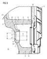
- FIG 3 shows the recess of the tub unit 2 without the sensor unit 6.
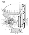
- the recess is formed as a gasket seat 38 for receiving and holding a gasket 18 of the sensor unit 6 as is shown in the mounted state in FIG 6 and FIG 7 .
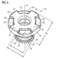
- FIG 4 shows an advantageous embodiment of the gasket 18,
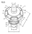
- FIG 5 shows a sensor unit 6 comprising this gasket 18 of FIG 4 with a sensor probe body 12 mounted therein.
- the gasket seat 38 of the tub unit 2 has a through hole 37 in a clamping section 10 formed by the tub unit 2.
- the through hole 37 has a diameter d and is preferably cylindrical or circular-shaped around a central axis A.
- the gasket seat 38 Adjacent to the clamping section 10 the gasket seat 38 comprises a circumferential wall 39 shaped preferably approximately cylindrically around the axis A and/or like a bushing or the like and enclosing a receiving space 31 having a (maximum) diameter Ds. At an end face of the circumferential wall 39 a bearing shoulder 11 is defined for bearing the contact portion 19 of the gasket 18 in the mounted state.
- the gasket seat 38 is, in the embodiment shown, preferably surrounded by circumferential wall(s) 9 which can be e.g. enforcement ribs of the tub unit 2.
- the circumferential walls 9 and 39 advantageously protrude in a direction opposite to the interior space 17 of the tub, i.e. in an outward direction.
- Joining portions 7a, 7b can be advantageously provided at the circumferential walls 9, to which the condenser unit 3 may be advantageously fixedly attached, e.g. by gluing or welding or in any other applicable way to form a water- and air-tight connection between tub unit 2 and condenser unit 3.
- the gasket 18 according to FIG 4 and 5 and FIG 6 and 7 has advantageously a central hole 26 around the central axis A, in which the sensor probe body 12 is or can be accommodated or fixed.
- the sensor probe body 12 is preferably at least partially cylindrical and/or has a diameter di which is slightly larger than the inner diameter of the central hole 26 to achieve a tight connection.
- the sensor probe body 12 can be advantageously provided with clamping ribs 13 which cooperate with corresponding clamping grooves 14 being provided in the clamping portion 20 of the gasket 18.
- the gasket 18 is preferably made from a resilient material such as an elastomeric material or rubber material. Furthermore, a ring 16 can be advantageously fixedly attached or integrally formed to the sensor probe body 12. The ring 16 can be accommodated within a corresponding free inner space preferably provided inside the gasket 18 to define a space for gluing or, in addition or alternatively, support the tight connection between sensor probe body 12 and gasket 18.
- the gasket 18 has a contact portion 19 and a clamping portion 20 arranged axially with respect to the axis A, preferably displaced one from another by an intermediate portion 36.
- the contact portion 19 is directly connected to the clamping portion 20, i.e. without any intermediate portion.
- the clamping portion 20 of the gasket 18 is positioned in the region of the clamping section 10 of the gasket seat 38.
- the clamping portion 20 of the gasket 18 has a diameter d' in the uncompressed state that is slightly larger than the diameter d of the through hole 37 in the clamping section 10 of the gasket seat 38.
- the clamping portion 20 of the gasket 18 is compressed within the through hole 37 in the mounted state and forms an air- and water-tight connection between gasket 18 and clamping portion 10.
- the intermediate portion 36 between the contact portion 19 and the clamping portion 20 of the gasket 18 is arranged within the receiving space 31 surrounded by the circumferential wall 39 advantageously at a distance or gap to the circumferential wall 39, thus not being in contact with the gasket seat 38.
- the intermediate portion 36 therefore has an outer diameter which is preferably smaller than the diameter Ds of the receiving space 31 and larger than the diameter d of the through hole 37 and preferably also larger than the diameter d' of the uncompressed clamping section 20 of the gasket 18.
- a securing portion 35 is arranged which is in the exemplary embodiment shown, is preferably ring-shaped and has advantageously a diameter D which is larger than the diameter d of the through hole 37.
- the axial end face 21 of the gasket 18 preferably acts as an actuation or gripping surface for a hand of a worker or a tool reaching to the gasket 18 from outside the tub for inserting the gasket 18 into its gasket seat 38, e.g. for pushing it into the through hole 37.
- the end face 21 is preferably formed in a special way, as described in the following, so as to allow for transfer of rotational forces/momentum onto the gasket 18 and, thus, rotational movement of the gasket 18 during mounting in the gasket seat 38 which improves and facilitates the mounting process significantly.
- the gasket 18 has at its front end face 21 an arrangement of engagement recesses 22 arranged at its circumference or periphery around the axis A, preferably at equal angular distances, and interposed engagement tongues (or wings or protrusions) 32 which reach to the circumference of the contact portion 19.
- the engagement recesses 22 are preferably open at their outside or towards the circumference or periphery of the end face 21 or contact portion 19, so that the recesses 22 can be accessed radially from the outside or bigger fingers or tool elements can reach outside.
- engagement recesses 22 and four engagement tongues (or wings or protrusions) 32 which are, preferably, arranged symmetrically at an angle of 90° to each other.
- the shape of the engagement recesses 22 and the engagement tongues 32 is preferably like a ring segment, although other shapes are of course possible.
- the gasket 18 shown has advantageously a rotational symmetry around the axis A wherein the contact portion 19 with the engagement recesses 22 and the engagement tongues 32 has a rotational symmetry with regard to multiples of 90° and the rest of the gasket has a rotational symmetry with regard to an arbitrary angle.
- two engagement recesses 22 are diametrically opposed with regard to the central axis A which allows for easy gripping by two fingers of a worker or two elements of a, e.g. fork-shaped, tool.
- the engagement recesses 22 and also the engagement tongues 32 constitute force receiving elements for receiving not only translational forces but in particular rotational forces or momentums around the axis A which are exerted manually or by means of a tool and facilitate the mounting of the sensor unit 6.
- Steps (or: grooves) 29 are preferably formed in the side walls of the engagement recesses 22 which further facilitate the gripping of the gasket 18.
- the steps 29 allow a transfer of a rotational force given by the worker's hand or the tool to the gasket 18.
- the gasket 18 can be pushed forward.
- the engagement recesses 22 and the steps 29 formed thereby it is possible to move the gasket 18 into the through hole 37 of the back wall 27 by a rotational movement in addition to a forward movement.
- engagement recesses 22 and engagement tongues 32 or force receiving elements in general can vary and be for instance only two, preferably arranged at an angle of 180°, or three, preferably arranged at an angle of 120°.
- the shape of the force receiving elements can vary in wide ranges, as long as a rotational force or momentum can be exerted onto the gasket 18 by gripping the force receiving elements arranged at the contact portion 19 at its end face 21.
- engagement recesses 22 instead of engagement recesses 22 also protruding parts such as lugs or pins or the like can be arranged at the end face 21 of the contact portion 19.
- the outer diameter of the contact portion 19 preferably corresponds to the outer diameter of the engagement tongues 32 and is designated by Da.
- the outer diameter Da is larger than the diameter Ds of the receiving space 31 and corresponds preferably to the outer diameter of the circumferential wall 39 so that the contact portion 19 bears on the bearing shoulder 11 axially with regard to the axis A over its complete surface.
- the outer dimensions of the circumferential wall 39 and the contact portion 19 can vary with respect to each other and do not have to be the same.
- the contact portion 19 is in flat or plane contact to the bearing shoulder 11 which improves the tightness of the connection between gasket 18 and tub unit 2.
- the gasket 18 is pushed forward while routeing at the same time until the forward movement is stopped when the contact portion 19 comes in contact with the bearing shoulder 11 and the securing portion 35 has passed the trough-hole 37. Then, the final position of the gasket 18 is reached.
- the bearing shoulder 11 can act advantageously as a stop to define the final axial position of the gasket 18 in the mounting direction.
- a flange 15 can also be fixedly attached to the sensor probe body 12 and abuts to an outer side of the contact portion 19.
- the cooperation of flange 15, ring 16 and clamping ribs 13 with the corresponding elements of the gasket 18 secure an air-and water-tight connection and a stable fixation of sensor probe body 12 and gasket 18.
- the through hole 37 is closed air- and water-tight by the sensor unit 6, wherein a cavity 8 is formed by the circumferential walls 9 and the gasket 18.
- the worker can pick up or grip the gasket 18 with e.g. two fingers and then can insert the gasket 18 into the through hole 37 in the back wall 27 by a pressing movement.
- the insertion is facilitated or relieved when the pressing movement is supported by a rotational movement of the gasket 18.
- the worker's fingers can add this rotational movement because of the engagement recesses 22 which form steps to transfer a rotational moment or a torque moment to the gasket 18.
- the clamping portion 20 is moved into position, where the clamping section 10 effects a clamping force on the clamped portion 20 and, thus, the gasket 18 is clamped in its intended place.
- a tool (not shown) is provided that is formed correspondingly to the contact portion 19 and to the axial end face with the force receiving element(s) (e.g. engagement recesses 22).
- the tool can have engagement elements that engage the force receiving element(s) in such a way that the gasket 18 can be inserted by means of the tool into the through hole of the back wall 27 of the tub unit 2 by combined forward and rotational movement.
- the tool for the insertion of the sensor unit 6 into its seat in the back wall 27 of the tub is adapted to the engagement recesses 22 and also to the sensor probe body 12 which protrudes in its longitudinal extension over the longitudinal extension of the gasket 18.
- the tool can be formed having engagement elements for engaging into the engagement recesses 22 and to engage around the protruding part of the sensor probe body 12. With such a tool it is possible to mount the complete sensor unit 6 into a seat in the back wall 27 of the tub.
- FIG 8 shows a front view of the internal side of the back wall of the tub unit 2 of the laundry treatment assembly 1.
- the tub unit 2 is shown without the drum.
- the bushing 24 can serve as a bearing for the drive shaft for the drum.
- An interior space 17 is defined by the walls of tub unit 2.
- the sensor unit 6 can be seen as it is arranged in its seat in a back wall 27 of the tub unit 2.
- the back wall 27 of the tub unit 2 preferably comprises several interior cavities 23 that are arranged circumferentially around a central portion of the back wall 27 of the tub unit 2. These interior cavities can be provided for supporting or stabilizing the mechanical structure of the tub unit 2.
- the interior cavities 23 are arranged in a region of the back wall 27 not comprising the bushing(s) 24 (in other words cavities 23 surrounds the bushings 24).
- cavities 23 are substantially parallelepiped-shaped, with an access opening substantially rectangular, preferably with the sides and/or the corners slightly rounded.
- a sump 25 is advantageously formed in a bottom region of the tub unit 2 .
- the sump 25 is in a ventilating connection with the condenser unit 3 via a flow channel 28.
- the flow channel 28 is at least partially formed to the back wall 27 of the tub unit 3.
- the sensor unit 6 In its mounted state, the sensor unit 6 is preferably arranged in a position where the sensitive part of the sensor probe body 12 can detect or measure air which is flowing inside the flow channel 28.
- the sensor unit 6 is placed adjacent or near an outlet of the flow channel 28 or a transition section of the flow channel 28 to the condenser unit 3.
- the sensor probe body 12 and the sensor unit 6 are preferably used or meant for sensing at least one process parameter of a laundry treatment process performed by the laundry machine within the interior space 17 of the laundry machine, wherein the process parameter is in particular a temperature.
Landscapes
- Engineering & Computer Science (AREA)
- Textile Engineering (AREA)
- Main Body Construction Of Washing Machines And Laundry Dryers (AREA)
- Control Of Washing Machine And Dryer (AREA)
Priority Applications (3)
| Application Number | Priority Date | Filing Date | Title |
|---|---|---|---|
| PL12157436T PL2634302T3 (pl) | 2012-02-29 | 2012-02-29 | Urządzenie pralnicze z jednostką czujnika |
| EP12157436.2A EP2634302B1 (fr) | 2012-02-29 | 2012-02-29 | Machine à laver avec unité de capteur |
| PCT/EP2013/053881 WO2013127822A2 (fr) | 2012-02-29 | 2013-02-27 | Machine à laver ayant une unité de capteur |
Applications Claiming Priority (1)
| Application Number | Priority Date | Filing Date | Title |
|---|---|---|---|
| EP12157436.2A EP2634302B1 (fr) | 2012-02-29 | 2012-02-29 | Machine à laver avec unité de capteur |
Publications (2)
| Publication Number | Publication Date |
|---|---|
| EP2634302A1 true EP2634302A1 (fr) | 2013-09-04 |
| EP2634302B1 EP2634302B1 (fr) | 2016-10-19 |
Family
ID=47754519
Family Applications (1)
| Application Number | Title | Priority Date | Filing Date |
|---|---|---|---|
| EP12157436.2A Not-in-force EP2634302B1 (fr) | 2012-02-29 | 2012-02-29 | Machine à laver avec unité de capteur |
Country Status (3)
| Country | Link |
|---|---|
| EP (1) | EP2634302B1 (fr) |
| PL (1) | PL2634302T3 (fr) |
| WO (1) | WO2013127822A2 (fr) |
Cited By (3)
| Publication number | Priority date | Publication date | Assignee | Title |
|---|---|---|---|---|
| EP3629879A4 (fr) * | 2017-05-30 | 2021-03-17 | Serdar Plastik Sanayi Ve Ticaret Anonim Sirketi | Boîtier de capteur de mesure de la pollution |
| EP2758583B2 (fr) † | 2011-09-19 | 2022-08-24 | Electrolux Home Products Corporation N.V. | Laveuse-sécheuse avec au moins un condensateur |
| EP4085815A1 (fr) * | 2021-05-04 | 2022-11-09 | Miele & Cie. KG | Lave-vaisselle |
Citations (3)
| Publication number | Priority date | Publication date | Assignee | Title |
|---|---|---|---|---|
| EP1048775A1 (fr) * | 1999-04-27 | 2000-11-02 | Miele & Cie. GmbH & Co. | Machine à laver à chargement frontal avec dispositif lumineaux |
| EP1458921A1 (fr) * | 2001-12-27 | 2004-09-22 | Lg Electronics Inc. | Machine a laver |
| WO2009066939A2 (fr) * | 2007-11-20 | 2009-05-28 | Lg Electronics Inc. | Machine de traitement du linge et détecteur permettant de détecter la qualité de l'eau associé |
-
2012
- 2012-02-29 PL PL12157436T patent/PL2634302T3/pl unknown
- 2012-02-29 EP EP12157436.2A patent/EP2634302B1/fr not_active Not-in-force
-
2013
- 2013-02-27 WO PCT/EP2013/053881 patent/WO2013127822A2/fr not_active Ceased
Patent Citations (4)
| Publication number | Priority date | Publication date | Assignee | Title |
|---|---|---|---|---|
| EP1048775A1 (fr) * | 1999-04-27 | 2000-11-02 | Miele & Cie. GmbH & Co. | Machine à laver à chargement frontal avec dispositif lumineaux |
| EP1458921A1 (fr) * | 2001-12-27 | 2004-09-22 | Lg Electronics Inc. | Machine a laver |
| EP1458921B1 (fr) | 2001-12-27 | 2008-05-07 | Lg Electronics Inc. | Machine a laver |
| WO2009066939A2 (fr) * | 2007-11-20 | 2009-05-28 | Lg Electronics Inc. | Machine de traitement du linge et détecteur permettant de détecter la qualité de l'eau associé |
Cited By (4)
| Publication number | Priority date | Publication date | Assignee | Title |
|---|---|---|---|---|
| EP2758583B2 (fr) † | 2011-09-19 | 2022-08-24 | Electrolux Home Products Corporation N.V. | Laveuse-sécheuse avec au moins un condensateur |
| EP3629879A4 (fr) * | 2017-05-30 | 2021-03-17 | Serdar Plastik Sanayi Ve Ticaret Anonim Sirketi | Boîtier de capteur de mesure de la pollution |
| EP4085815A1 (fr) * | 2021-05-04 | 2022-11-09 | Miele & Cie. KG | Lave-vaisselle |
| BE1029372B1 (de) * | 2021-05-04 | 2022-12-05 | Miele & Cie | Geschirrspülmaschine |
Also Published As
| Publication number | Publication date |
|---|---|
| PL2634302T3 (pl) | 2017-08-31 |
| WO2013127822A3 (fr) | 2013-12-19 |
| WO2013127822A2 (fr) | 2013-09-06 |
| EP2634302B1 (fr) | 2016-10-19 |
Similar Documents
| Publication | Publication Date | Title |
|---|---|---|
| EP2387643B1 (fr) | Sèche-linge comprenant un capteur de siccité | |
| EP2634302B1 (fr) | Machine à laver avec unité de capteur | |
| KR102178451B1 (ko) | 의류건조기 | |
| US8516716B2 (en) | Laundry dryer with gasket-supporting collar | |
| EP1997951A1 (fr) | Machine à laver le linge | |
| EP2876197B1 (fr) | Machine à laver avec ensemble tiroir | |
| EP2620541A1 (fr) | Machine pour sécher le linge | |
| CN103518015A (zh) | 具有湿度传感器系统的滚筒式干衣机 | |
| JP6349069B2 (ja) | ドラム式洗濯機 | |
| JP2007516370A (ja) | 筐体 | |
| US10584437B2 (en) | Drum type washing machine | |
| JP5274948B2 (ja) | 温度センサの取付構造 | |
| CN101563497B (zh) | 具有背后的入口盖的蒸汽熨烫装置 | |
| EP2843114A1 (fr) | Sèche-linge à tambour rotatif | |
| KR20100037449A (ko) | 세탁물 처리기기 | |
| WO2011080114A1 (fr) | Sèche-linge | |
| WO2010076131A1 (fr) | Séchoir comprenant un capteur de siccité | |
| US20250116459A1 (en) | Food waste disposer | |
| WO2014161787A1 (fr) | Lave-linge/sèche-linge comprenant un verrou | |
| US10648114B2 (en) | Wall-mounted washing machine | |
| EP2631356B1 (fr) | Sèche-linge à tambour rotatif | |
| EP1291480A1 (fr) | Poignée extérieure pour véhicule | |
| HUE030214T2 (hu) | Kefeelrendezés villamos gép kommutátor-egységéhez | |
| KR100509337B1 (ko) | 전기압력밥솥의 온도센서 장착장치 | |
| KR20110056147A (ko) | 조리기기 |
Legal Events
| Date | Code | Title | Description |
|---|---|---|---|
| PUAI | Public reference made under article 153(3) epc to a published international application that has entered the european phase |
Free format text: ORIGINAL CODE: 0009012 |
|
| AK | Designated contracting states |
Kind code of ref document: A1 Designated state(s): AL AT BE BG CH CY CZ DE DK EE ES FI FR GB GR HR HU IE IS IT LI LT LU LV MC MK MT NL NO PL PT RO RS SE SI SK SM TR |
|
| AX | Request for extension of the european patent |
Extension state: BA ME |
|
| 17P | Request for examination filed |
Effective date: 20140304 |
|
| RBV | Designated contracting states (corrected) |
Designated state(s): AL AT BE BG CH CY CZ DE DK EE ES FI FR GB GR HR HU IE IS IT LI LT LU LV MC MK MT NL NO PL PT RO RS SE SI SK SM TR |
|
| RIC1 | Information provided on ipc code assigned before grant |
Ipc: D06F 37/26 20060101ALI20140321BHEP Ipc: D06F 39/00 20060101AFI20140321BHEP |
|
| GRAP | Despatch of communication of intention to grant a patent |
Free format text: ORIGINAL CODE: EPIDOSNIGR1 |
|
| INTG | Intention to grant announced |
Effective date: 20160725 |
|
| GRAS | Grant fee paid |
Free format text: ORIGINAL CODE: EPIDOSNIGR3 |
|
| GRAA | (expected) grant |
Free format text: ORIGINAL CODE: 0009210 |
|
| AK | Designated contracting states |
Kind code of ref document: B1 Designated state(s): AL AT BE BG CH CY CZ DE DK EE ES FI FR GB GR HR HU IE IS IT LI LT LU LV MC MK MT NL NO PL PT RO RS SE SI SK SM TR |
|
| REG | Reference to a national code |
Ref country code: GB Ref legal event code: FG4D |
|
| REG | Reference to a national code |
Ref country code: CH Ref legal event code: EP |
|
| REG | Reference to a national code |
Ref country code: AT Ref legal event code: REF Ref document number: 838442 Country of ref document: AT Kind code of ref document: T Effective date: 20161115 |
|
| REG | Reference to a national code |
Ref country code: IE Ref legal event code: FG4D |
|
| REG | Reference to a national code |
Ref country code: DE Ref legal event code: R096 Ref document number: 602012024235 Country of ref document: DE |
|
| REG | Reference to a national code |
Ref country code: NL Ref legal event code: MP Effective date: 20161019 |
|
| REG | Reference to a national code |
Ref country code: LT Ref legal event code: MG4D |
|
| PG25 | Lapsed in a contracting state [announced via postgrant information from national office to epo] |
Ref country code: LV Free format text: LAPSE BECAUSE OF FAILURE TO SUBMIT A TRANSLATION OF THE DESCRIPTION OR TO PAY THE FEE WITHIN THE PRESCRIBED TIME-LIMIT Effective date: 20161019 |
|
| REG | Reference to a national code |
Ref country code: AT Ref legal event code: MK05 Ref document number: 838442 Country of ref document: AT Kind code of ref document: T Effective date: 20161019 |
|
| PG25 | Lapsed in a contracting state [announced via postgrant information from national office to epo] |
Ref country code: NO Free format text: LAPSE BECAUSE OF FAILURE TO SUBMIT A TRANSLATION OF THE DESCRIPTION OR TO PAY THE FEE WITHIN THE PRESCRIBED TIME-LIMIT Effective date: 20170119 Ref country code: LT Free format text: LAPSE BECAUSE OF FAILURE TO SUBMIT A TRANSLATION OF THE DESCRIPTION OR TO PAY THE FEE WITHIN THE PRESCRIBED TIME-LIMIT Effective date: 20161019 Ref country code: GR Free format text: LAPSE BECAUSE OF FAILURE TO SUBMIT A TRANSLATION OF THE DESCRIPTION OR TO PAY THE FEE WITHIN THE PRESCRIBED TIME-LIMIT Effective date: 20170120 Ref country code: SE Free format text: LAPSE BECAUSE OF FAILURE TO SUBMIT A TRANSLATION OF THE DESCRIPTION OR TO PAY THE FEE WITHIN THE PRESCRIBED TIME-LIMIT Effective date: 20161019 |
|
| PG25 | Lapsed in a contracting state [announced via postgrant information from national office to epo] |
Ref country code: ES Free format text: LAPSE BECAUSE OF FAILURE TO SUBMIT A TRANSLATION OF THE DESCRIPTION OR TO PAY THE FEE WITHIN THE PRESCRIBED TIME-LIMIT Effective date: 20161019 Ref country code: RS Free format text: LAPSE BECAUSE OF FAILURE TO SUBMIT A TRANSLATION OF THE DESCRIPTION OR TO PAY THE FEE WITHIN THE PRESCRIBED TIME-LIMIT Effective date: 20161019 Ref country code: NL Free format text: LAPSE BECAUSE OF FAILURE TO SUBMIT A TRANSLATION OF THE DESCRIPTION OR TO PAY THE FEE WITHIN THE PRESCRIBED TIME-LIMIT Effective date: 20161019 Ref country code: BE Free format text: LAPSE BECAUSE OF FAILURE TO SUBMIT A TRANSLATION OF THE DESCRIPTION OR TO PAY THE FEE WITHIN THE PRESCRIBED TIME-LIMIT Effective date: 20161019 Ref country code: PT Free format text: LAPSE BECAUSE OF FAILURE TO SUBMIT A TRANSLATION OF THE DESCRIPTION OR TO PAY THE FEE WITHIN THE PRESCRIBED TIME-LIMIT Effective date: 20170220 Ref country code: HR Free format text: LAPSE BECAUSE OF FAILURE TO SUBMIT A TRANSLATION OF THE DESCRIPTION OR TO PAY THE FEE WITHIN THE PRESCRIBED TIME-LIMIT Effective date: 20161019 Ref country code: IS Free format text: LAPSE BECAUSE OF FAILURE TO SUBMIT A TRANSLATION OF THE DESCRIPTION OR TO PAY THE FEE WITHIN THE PRESCRIBED TIME-LIMIT Effective date: 20170219 Ref country code: AT Free format text: LAPSE BECAUSE OF FAILURE TO SUBMIT A TRANSLATION OF THE DESCRIPTION OR TO PAY THE FEE WITHIN THE PRESCRIBED TIME-LIMIT Effective date: 20161019 Ref country code: FI Free format text: LAPSE BECAUSE OF FAILURE TO SUBMIT A TRANSLATION OF THE DESCRIPTION OR TO PAY THE FEE WITHIN THE PRESCRIBED TIME-LIMIT Effective date: 20161019 |
|
| REG | Reference to a national code |
Ref country code: DE Ref legal event code: R097 Ref document number: 602012024235 Country of ref document: DE |
|
| PG25 | Lapsed in a contracting state [announced via postgrant information from national office to epo] |
Ref country code: CZ Free format text: LAPSE BECAUSE OF FAILURE TO SUBMIT A TRANSLATION OF THE DESCRIPTION OR TO PAY THE FEE WITHIN THE PRESCRIBED TIME-LIMIT Effective date: 20161019 Ref country code: RO Free format text: LAPSE BECAUSE OF FAILURE TO SUBMIT A TRANSLATION OF THE DESCRIPTION OR TO PAY THE FEE WITHIN THE PRESCRIBED TIME-LIMIT Effective date: 20161019 Ref country code: EE Free format text: LAPSE BECAUSE OF FAILURE TO SUBMIT A TRANSLATION OF THE DESCRIPTION OR TO PAY THE FEE WITHIN THE PRESCRIBED TIME-LIMIT Effective date: 20161019 Ref country code: SK Free format text: LAPSE BECAUSE OF FAILURE TO SUBMIT A TRANSLATION OF THE DESCRIPTION OR TO PAY THE FEE WITHIN THE PRESCRIBED TIME-LIMIT Effective date: 20161019 Ref country code: DK Free format text: LAPSE BECAUSE OF FAILURE TO SUBMIT A TRANSLATION OF THE DESCRIPTION OR TO PAY THE FEE WITHIN THE PRESCRIBED TIME-LIMIT Effective date: 20161019 |
|
| PLBE | No opposition filed within time limit |
Free format text: ORIGINAL CODE: 0009261 |
|
| STAA | Information on the status of an ep patent application or granted ep patent |
Free format text: STATUS: NO OPPOSITION FILED WITHIN TIME LIMIT |
|
| PG25 | Lapsed in a contracting state [announced via postgrant information from national office to epo] |
Ref country code: BG Free format text: LAPSE BECAUSE OF FAILURE TO SUBMIT A TRANSLATION OF THE DESCRIPTION OR TO PAY THE FEE WITHIN THE PRESCRIBED TIME-LIMIT Effective date: 20170119 Ref country code: SM Free format text: LAPSE BECAUSE OF FAILURE TO SUBMIT A TRANSLATION OF THE DESCRIPTION OR TO PAY THE FEE WITHIN THE PRESCRIBED TIME-LIMIT Effective date: 20161019 |
|
| 26N | No opposition filed |
Effective date: 20170720 |
|
| PG25 | Lapsed in a contracting state [announced via postgrant information from national office to epo] |
Ref country code: MC Free format text: LAPSE BECAUSE OF FAILURE TO SUBMIT A TRANSLATION OF THE DESCRIPTION OR TO PAY THE FEE WITHIN THE PRESCRIBED TIME-LIMIT Effective date: 20161019 |
|
| REG | Reference to a national code |
Ref country code: CH Ref legal event code: PL |
|
| GBPC | Gb: european patent ceased through non-payment of renewal fee |
Effective date: 20170228 |
|
| PG25 | Lapsed in a contracting state [announced via postgrant information from national office to epo] |
Ref country code: LI Free format text: LAPSE BECAUSE OF NON-PAYMENT OF DUE FEES Effective date: 20170228 Ref country code: CH Free format text: LAPSE BECAUSE OF NON-PAYMENT OF DUE FEES Effective date: 20170228 |
|
| REG | Reference to a national code |
Ref country code: IE Ref legal event code: MM4A |
|
| PG25 | Lapsed in a contracting state [announced via postgrant information from national office to epo] |
Ref country code: SI Free format text: LAPSE BECAUSE OF FAILURE TO SUBMIT A TRANSLATION OF THE DESCRIPTION OR TO PAY THE FEE WITHIN THE PRESCRIBED TIME-LIMIT Effective date: 20161019 |
|
| REG | Reference to a national code |
Ref country code: FR Ref legal event code: ST Effective date: 20171031 |
|
| PG25 | Lapsed in a contracting state [announced via postgrant information from national office to epo] |
Ref country code: LU Free format text: LAPSE BECAUSE OF NON-PAYMENT OF DUE FEES Effective date: 20170228 |
|
| PG25 | Lapsed in a contracting state [announced via postgrant information from national office to epo] |
Ref country code: FR Free format text: LAPSE BECAUSE OF NON-PAYMENT OF DUE FEES Effective date: 20170228 |
|
| PG25 | Lapsed in a contracting state [announced via postgrant information from national office to epo] |
Ref country code: IE Free format text: LAPSE BECAUSE OF NON-PAYMENT OF DUE FEES Effective date: 20170228 Ref country code: GB Free format text: LAPSE BECAUSE OF NON-PAYMENT OF DUE FEES Effective date: 20170228 |
|
| PG25 | Lapsed in a contracting state [announced via postgrant information from national office to epo] |
Ref country code: MT Free format text: LAPSE BECAUSE OF NON-PAYMENT OF DUE FEES Effective date: 20170228 |
|
| PG25 | Lapsed in a contracting state [announced via postgrant information from national office to epo] |
Ref country code: HU Free format text: LAPSE BECAUSE OF FAILURE TO SUBMIT A TRANSLATION OF THE DESCRIPTION OR TO PAY THE FEE WITHIN THE PRESCRIBED TIME-LIMIT; INVALID AB INITIO Effective date: 20120229 |
|
| PG25 | Lapsed in a contracting state [announced via postgrant information from national office to epo] |
Ref country code: CY Free format text: LAPSE BECAUSE OF NON-PAYMENT OF DUE FEES Effective date: 20161019 |
|
| PG25 | Lapsed in a contracting state [announced via postgrant information from national office to epo] |
Ref country code: MK Free format text: LAPSE BECAUSE OF FAILURE TO SUBMIT A TRANSLATION OF THE DESCRIPTION OR TO PAY THE FEE WITHIN THE PRESCRIBED TIME-LIMIT Effective date: 20161019 |
|
| PG25 | Lapsed in a contracting state [announced via postgrant information from national office to epo] |
Ref country code: TR Free format text: LAPSE BECAUSE OF FAILURE TO SUBMIT A TRANSLATION OF THE DESCRIPTION OR TO PAY THE FEE WITHIN THE PRESCRIBED TIME-LIMIT Effective date: 20161019 |
|
| PG25 | Lapsed in a contracting state [announced via postgrant information from national office to epo] |
Ref country code: AL Free format text: LAPSE BECAUSE OF FAILURE TO SUBMIT A TRANSLATION OF THE DESCRIPTION OR TO PAY THE FEE WITHIN THE PRESCRIBED TIME-LIMIT Effective date: 20161019 |
|
| PGFP | Annual fee paid to national office [announced via postgrant information from national office to epo] |
Ref country code: PL Payment date: 20230203 Year of fee payment: 12 Ref country code: IT Payment date: 20230220 Year of fee payment: 12 Ref country code: DE Payment date: 20230227 Year of fee payment: 12 |
|
| P01 | Opt-out of the competence of the unified patent court (upc) registered |
Effective date: 20230625 |
|
| REG | Reference to a national code |
Ref country code: DE Ref legal event code: R119 Ref document number: 602012024235 Country of ref document: DE |
|
| PG25 | Lapsed in a contracting state [announced via postgrant information from national office to epo] |
Ref country code: DE Free format text: LAPSE BECAUSE OF NON-PAYMENT OF DUE FEES Effective date: 20240903 |
|
| PG25 | Lapsed in a contracting state [announced via postgrant information from national office to epo] |
Ref country code: DE Free format text: LAPSE BECAUSE OF NON-PAYMENT OF DUE FEES Effective date: 20240903 |
|
| PG25 | Lapsed in a contracting state [announced via postgrant information from national office to epo] |
Ref country code: IT Free format text: LAPSE BECAUSE OF NON-PAYMENT OF DUE FEES Effective date: 20240229 |
|
| PG25 | Lapsed in a contracting state [announced via postgrant information from national office to epo] |
Ref country code: PL Free format text: LAPSE BECAUSE OF NON-PAYMENT OF DUE FEES Effective date: 20240229 |