EP2634323B1 - Dispositif d'assemblage - Google Patents
Dispositif d'assemblage Download PDFInfo
- Publication number
- EP2634323B1 EP2634323B1 EP13156668.9A EP13156668A EP2634323B1 EP 2634323 B1 EP2634323 B1 EP 2634323B1 EP 13156668 A EP13156668 A EP 13156668A EP 2634323 B1 EP2634323 B1 EP 2634323B1
- Authority
- EP
- European Patent Office
- Prior art keywords
- rotating body
- opening
- rotation
- coupling
- axis
- Prior art date
- Legal status (The legal status is an assumption and is not a legal conclusion. Google has not performed a legal analysis and makes no representation as to the accuracy of the status listed.)
- Active
Links
- 230000008878 coupling Effects 0.000 claims description 27
- 238000010168 coupling process Methods 0.000 claims description 27
- 238000005859 coupling reaction Methods 0.000 claims description 27
- 229910000831 Steel Inorganic materials 0.000 description 7
- 239000010959 steel Substances 0.000 description 7
- 238000011065 in-situ storage Methods 0.000 description 4
- 238000005352 clarification Methods 0.000 description 1
- 238000010276 construction Methods 0.000 description 1
- 230000000694 effects Effects 0.000 description 1
- 238000004519 manufacturing process Methods 0.000 description 1
- 230000002093 peripheral effect Effects 0.000 description 1
- 229910052705 radium Inorganic materials 0.000 description 1
- 238000003860 storage Methods 0.000 description 1
- 230000007704 transition Effects 0.000 description 1
Images
Classifications
-
- E—FIXED CONSTRUCTIONS
- E04—BUILDING
- E04B—GENERAL BUILDING CONSTRUCTIONS; WALLS, e.g. PARTITIONS; ROOFS; FLOORS; CEILINGS; INSULATION OR OTHER PROTECTION OF BUILDINGS
- E04B1/00—Constructions in general; Structures which are not restricted either to walls, e.g. partitions, or floors or ceilings or roofs
- E04B1/38—Connections for building structures in general
- E04B1/61—Connections for building structures in general of slab-shaped building elements with each other
- E04B1/6108—Connections for building structures in general of slab-shaped building elements with each other the frontal surfaces of the slabs connected together
- E04B1/612—Connections for building structures in general of slab-shaped building elements with each other the frontal surfaces of the slabs connected together by means between frontal surfaces
- E04B1/6183—Connections for building structures in general of slab-shaped building elements with each other the frontal surfaces of the slabs connected together by means between frontal surfaces with rotatable locking means co-operating with a recess
-
- E—FIXED CONSTRUCTIONS
- E05—LOCKS; KEYS; WINDOW OR DOOR FITTINGS; SAFES
- E05B—LOCKS; ACCESSORIES THEREFOR; HANDCUFFS
- E05B65/00—Locks or fastenings for special use
- E05B65/006—Locks or fastenings for special use for covers or panels
-
- E—FIXED CONSTRUCTIONS
- E04—BUILDING
- E04B—GENERAL BUILDING CONSTRUCTIONS; WALLS, e.g. PARTITIONS; ROOFS; FLOORS; CEILINGS; INSULATION OR OTHER PROTECTION OF BUILDINGS
- E04B1/00—Constructions in general; Structures which are not restricted either to walls, e.g. partitions, or floors or ceilings or roofs
- E04B1/02—Structures consisting primarily of load-supporting, block-shaped, or slab-shaped elements
- E04B1/04—Structures consisting primarily of load-supporting, block-shaped, or slab-shaped elements the elements consisting of concrete, e.g. reinforced concrete, or other stone-like material
- E04B1/043—Connections specially adapted therefor
-
- E—FIXED CONSTRUCTIONS
- E05—LOCKS; KEYS; WINDOW OR DOOR FITTINGS; SAFES
- E05B—LOCKS; ACCESSORIES THEREFOR; HANDCUFFS
- E05B65/00—Locks or fastenings for special use
- E05B65/08—Locks or fastenings for special use for sliding wings
- E05B65/0811—Locks or fastenings for special use for sliding wings the bolts pivoting about an axis perpendicular to the wings
- E05B65/0817—Locks or fastenings for special use for sliding wings the bolts pivoting about an axis perpendicular to the wings with additional movement, e.g. toggle, overcenter, excentric
Definitions
- the invention relates to a device for connecting wall and / or ceiling components in the construction of buildings, with a connecting element having a connecting body with means for coupling one of the components to the connecting body and a rotatable against the connecting body rotary body with means for coupling the other component to the rotary body eccentric to its axis of rotation, wherein the rotary body is rotatable in an opening in the connecting body to generate by the connecting element on the coupled components transverse to the rotational axis of the rotary body tensile forces exerted.
- Such a device for connecting wall or / and ceiling components is in the DE 10 2007 015 830 A1 described.
- the connecting element of this known device can be coupled to a U-shaped, cast into the concrete of the wall and / or ceiling components steel rods, wherein the connecting body is designed as a couplable to the U-shaped steel rod hook.
- a circular opening in the connecting body of the rotary body is mounted, projecting axially from each of its two sides an eccentrically arranged axle journal.
- Each of the stub axles is encompassed by a U-shaped bent steel rod.
- the invention has for its object to provide a new, safe from unwanted loosening connection device.
- the device according to the invention which achieves this object is characterized in that the opening has an extension which extends counter to the tensile force exerted on the other component by the rotary body and which narrows in its width below the diameter of the rotary body.
- the pulling force exerted by the rotary body on one of the wall and / or ceiling components to be connected ensures that the rotary body acts from the moment in which a coupling between the connecting body and one of the components takes effect, for example when a hook part of the connecting body engages begins, the rotary body enters the constriction and wedged in the constriction with increasing tensile stress.
- the wedging is so strong that it can not come under any circumstances to a loosening of the rotating body, not even if a torque is applied via the coupling to the body to be connected to the rotary body by the effective tensile force.
- the constriction has a constant wedge angle in a portion of the extension.
- the clamping force increases steadily with increasing depth of entry into the constriction.
- the length of the section is 3% to 15% of the diameter of the rotating body.
- the wedge angle preferably moves between 5 ° to 15 °.
- the constant wedge angle is 9 °.
- the opening has different radii with radius centers arranged at a distance from each other.
- the section in which the wedge angle of the constriction remains constant lies between the respective points of contact of the tangents on both circles corresponding to the radii.
- the rotary body is formed exclusively by a circular plate, wherein the axis of rotation of the rotary body is perpendicular to the plate planes and extends through the center of the circle.
- a seat opening to one of the plate planes may be formed for receiving a turning tool.
- the means for coupling the other part suitably comprise an opening arranged offset with respect to the axis of rotation, in particular a passage opening into which a bent or U-shaped steel rod, e.g. embedded in the concrete wall components to be joined together, can intervene.
- the rotary body is secured in the opening up to a limit torque by a lock relative to the connecting body against rotation.
- the lock may be, for example, by a shear body extending into a recess in the rotating body and the connecting body, e.g. be formed by a shear-off pin.
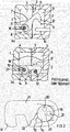
- Fig. 1 shows sections of concrete building boards 1 and 2, which are perpendicular to each other and form a room wall corner in a building erected by such concrete building boards (not shown).
- the abutting at 3 concrete slabs 1 and 2 each have a recess open on one side 4 and 5 respectively. Through the recesses 4 and 5 is formed when joining the plates, a closed space. 6
- a connecting element 7 is arranged, that is pivotally held on a cast in the concrete building board 1 coupling element 8 as indicated by arrow 9.
- a cast in the concrete building board 2 coupling counter-element 10 protrudes into the formed by the recess 5 portion of the space 6 inside.
- the Coupling element 8 comprises two U-shaped bent steel strand, the coupling counter-element 10 only such a steel strand.
- the connecting element 7 comprises a plate-shaped connecting body 11 with an undercut hook leg 12 at one end.
- a circular opening 13 for the storage of a circular rotating body 14 is formed.
- the rotary body 14 is eccentrically to its axis of rotation on each side of a journal 15, which engages in one of the two U-bend of the coupling element 8 respectively.
- the journal 15 has a frontal seat 16 for engagement of a hexagon turning tool, which is aligned to a (not shown) opening channel in the concrete slab 1.
- the connecting element 7 is pivoted by means of said hexagonal tool, the hook leg 12 engages between the U-legs of the coupling counter-element 10 and the connecting body 7 finally comes to rest on the coupling counter-element.
- a grain attached to the peripheral surface of the rotary body 14 and / or the inner surface of the opening 13 prevents the connector body 11 from moving relative to the rotary body 14 during this phase. From the time of the stop of the connecting body 11 against the coupling counter-element 10 is caused by further rotation of the rotary body 14 by means of the hexagonal turning tool caused by the grain locking of the rotary body 14 and the rotary body 14 in the in Fig. 1 b shown rotated position in which the hook leg 12 according to arrow 17 exerts a pulling force on the coupling counter-element 10.
- connection lock By a further (not shown) opening, which is arranged above the aligned to the seat 16 passage opening, the cavity 6 is then poured with in-situ concrete 18 and fixed the connecting element 7 in the position shown. Disadvantageously, before this fixation by the hardened in-situ concrete 18 by unintentional rotation of the rotary body 14 against the connecting body 11, the connection lock.
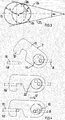
- the opening 13 in the connecting body 11 is not circular, but on its side facing away from the hook leg 12 has an extension 19.
- the width of the extension narrows below the diameter of the rotary body 14, wherein the wedge angle a of the constriction over a portion of the extension 19 is constant.
- the opening 13 is based on two circular openings whose centers are offset from each other in the direction mentioned and whose radii differ slightly.
- the inner wall of the opening 13 is bounded by the tangents to both circles, whereby the constriction area results with the constant wedge angle over a certain distance.
- the opening 13 has a first radius r 1 with a first radius center and in the region of the extension a second radius r 2 with a second radium center which is at a distance s from the first radius center. Between points where tangents 24 and 25 touch the circles corresponding to the radii r 1 and r 2 , the opening 13 is bounded by said tangents 24 and 25. In this section 26 delimited by the tangents, the wedge angle ⁇ of the constriction enclosed between the tangents 24, 25 is constant.
- the circular rotary body 14 has a seat 20 for the engagement of a hexagonal tool and an axis of rotation 23 of the rotary body 14 eccentrically arranged, extending in the axial direction through hole 21 for the coupling of a coupling element. Both the seat 20 and the through hole are formed directly in the rotary body, which is like the connecting body 11 plate-shaped.
- the reference numeral 22 indicates a shear-off pin, which ensures a co-movement of the connecting body 11 with the rotary body 14 up to a limit torque.
- the connecting element 7 is located on the coupling body 11 on the coupling counter-element 10, which thus prevents further rotation of the connecting element 7 in its entirety.
- the pin 22 can now be sheared off and the rotary body 14 can rotate in the opening 13 against the connecting body 11.
- the connecting body 11 shifts, inter alia, in the direction of the arrow 17 and the coupling counterpart 10 comes to bear against the undercut hook leg 12 of the connecting body 11.
- the rotary body shifts 14 now in the narrowing of the extension 19 of the opening 13 into and wedged in the constriction.
- the rotary body 14 is now rotatably locked in the opening 13 such that regardless of the rotational position of the rotary body 14, that is, regardless of whether the coupling element 8 on the rotary body 14 has a torque or not, there is no tendency to loosen the connection.
- connection device according to the prior art as far as possible avoided torque
- the device according to the invention avoids this disadvantage.
- a large rotational range of the rotary body 14 is available for the closed position.
- the device according to the invention allows a secure mounting of wall components, by in the phase in which in the cavity is not filled in situ fixing concrete, there is no risk to loosen the connection.
Landscapes
- Engineering & Computer Science (AREA)
- Architecture (AREA)
- Physics & Mathematics (AREA)
- Electromagnetism (AREA)
- Civil Engineering (AREA)
- Structural Engineering (AREA)
- Joining Of Building Structures In Genera (AREA)
- Building Environments (AREA)
Claims (10)
- Dispositif pour assembler des éléments de paroi et/ou de plafond lors de la construction de bâtiments, présentant un élément de liaison (7), qui présente un corps de liaison (11) pourvu de dispositifs pour l'accouplement d'un des éléments (8,10) au corps de liaison (11) et un corps rotatif (14) pouvant être tourné contre le corps de liaison (11) présentant des dispositifs pour l'accouplement de l'autre élément (8) au corps rotatif (14) de manière excentrique par rapport à son axe de rotation, le corps rotatif (14) pouvant tourner dans une ouverture (13) dans le corps de liaison (11) avec génération de forces de traction exercées par l'élément de liaison (7) aux éléments accouplés (8,10) transversalement par rapport à l'axe de rotation du corps de rotation (14), caractérisé en ce que l'ouverture (13) présente un prolongement (19) s'étendant contre la force de traction exercée par le corps rotatif (14) sur l'autre pièce (8), se rétrécissant dans sa largeur sous le diamètre du corps rotatif (14).
- Dispositif selon la revendication 1, caractérisé en ce que le rétrécissement présente une section pourvue d'un angle d'inclinaison α constant de rétrécissement.
- Dispositif selon la revendication 2, caractérisé en ce que la longueur de la section représente 3% à 15% du diamètre du corps rotatif (14).
- Dispositif selon l'une quelconque des revendications 1 à 3, caractérisé en ce que l'angle d'inclinaison du rétrécissement est de 5° à 15° et en particulier, l'angle d'inclinaison constant est de 9°.
- Dispositif selon l'une quelconque des revendications 1 à 4, caractérisé en ce que l'ouverture (13) présente différents rayons (r1, r2) pourvus de points centraux de rayon disposés à une certaine distance (s) l'un par rapport à l'autre.
- Dispositif selon l'une quelconque des revendications 1 à 5, caractérisé en ce que le corps rotatif (14) est formé exclusivement par une plaque circulaire et l'axe de rotation du corps rotatif (14) s'étend perpendiculairement par rapport au plan de la plaque à travers le centre du cercle.
- Dispositif selon la revendication 6, caractérisé en ce qu'un siège (20), s'ouvrant vers l'un des plans de la plaque, destiné à recevoir un outil rotatif, est formé dans la plaque.
- Dispositif selon l'une quelconque des revendications 1 ou 7, caractérisé en ce que les dispositifs pour l'accouplement de l'autre partie (8) présentent, dans le corps rotatif (14), une ouverture, en particulier une ouverture traversante (21) disposée de manière décalée par rapport à l'axe de rotation (23) du corps rotatif (14).
- Dispositif selon l'une quelconque des revendications 1 à 8, caractérisé en ce que le corps rotatif (14) est protégé contre une rotation par un dispositif de blocage (22) pouvant être sollicité jusqu'à un couple limite.
- Dispositif selon la revendication 9, caractérisé en ce que le dispositif de blocage est formé par un corps (22) pouvant être cisaillé, s'encliquetant dans le corps rotatif (14) et le corps de liaison (11).
Applications Claiming Priority (1)
| Application Number | Priority Date | Filing Date | Title |
|---|---|---|---|
| DE102012101639A DE102012101639A1 (de) | 2012-02-29 | 2012-02-29 | Verbindungsvorrichtung |
Publications (3)
| Publication Number | Publication Date |
|---|---|
| EP2634323A2 EP2634323A2 (fr) | 2013-09-04 |
| EP2634323A3 EP2634323A3 (fr) | 2014-03-26 |
| EP2634323B1 true EP2634323B1 (fr) | 2017-01-18 |
Family
ID=47900558
Family Applications (1)
| Application Number | Title | Priority Date | Filing Date |
|---|---|---|---|
| EP13156668.9A Active EP2634323B1 (fr) | 2012-02-29 | 2013-02-26 | Dispositif d'assemblage |
Country Status (3)
| Country | Link |
|---|---|
| EP (1) | EP2634323B1 (fr) |
| DE (1) | DE102012101639A1 (fr) |
| DK (1) | DK2634323T3 (fr) |
Families Citing this family (1)
| Publication number | Priority date | Publication date | Assignee | Title |
|---|---|---|---|---|
| DE102014117832A1 (de) | 2014-12-04 | 2016-06-09 | Christian Weidemann | Vorrichtung zum Verbinden von Wand- oder/und Deckenbauteilen beim Errichten von Bauten |
Citations (1)
| Publication number | Priority date | Publication date | Assignee | Title |
|---|---|---|---|---|
| CH98264A (fr) * | 1921-07-21 | 1923-03-01 | Rohmer Gabriel Emile | Tampon de scellement. |
Family Cites Families (1)
| Publication number | Priority date | Publication date | Assignee | Title |
|---|---|---|---|---|
| DE102007015830A1 (de) | 2007-03-30 | 2008-10-02 | Weidemann, Christian | Vorrichtung zum Verbinden von Wand- oder/und Deckenbauteilen |
-
2012
- 2012-02-29 DE DE102012101639A patent/DE102012101639A1/de not_active Withdrawn
-
2013
- 2013-02-26 EP EP13156668.9A patent/EP2634323B1/fr active Active
- 2013-02-26 DK DK13156668.9T patent/DK2634323T3/en active
Patent Citations (1)
| Publication number | Priority date | Publication date | Assignee | Title |
|---|---|---|---|---|
| CH98264A (fr) * | 1921-07-21 | 1923-03-01 | Rohmer Gabriel Emile | Tampon de scellement. |
Also Published As
| Publication number | Publication date |
|---|---|
| EP2634323A2 (fr) | 2013-09-04 |
| EP2634323A3 (fr) | 2014-03-26 |
| DK2634323T3 (en) | 2017-05-01 |
| DE102012101639A1 (de) | 2013-08-29 |
Similar Documents
| Publication | Publication Date | Title |
|---|---|---|
| EP2678571B1 (fr) | Dispositif d'assemblage d'angle pour profilés creux | |
| EP3214234B1 (fr) | Connecteur pour éléments préfabriqués et systeme de connection pour éléments préfabriqués en béton | |
| WO2005040526A1 (fr) | Systeme de coffrage | |
| DE1650975A1 (de) | Vorrichtung zum Anschliessen bzw. Verbinden von Bauelementen | |
| EP2786026A1 (fr) | Barre profilée, assemblage de profilés et procédé de fabrication d'un assemblage de profilés | |
| EP3529430B1 (fr) | Montant pour une construction à montant et traverse | |
| EP2636830B1 (fr) | Fixation de penture, ensemble avec fixation de penture et penture ainsi qu'agencement de porte | |
| EP3214235B1 (fr) | Systeme de connection de pieces préfabriquées en beton | |
| AT519093B1 (de) | Verbindungsvorrichtung zur Verbindung von dünnwandigen Fertigteilen und damit ausgestattete Fertigteile | |
| DE102007015830A1 (de) | Vorrichtung zum Verbinden von Wand- oder/und Deckenbauteilen | |
| EP2634323B1 (fr) | Dispositif d'assemblage | |
| DE102014106068B4 (de) | Vorrichtung zur Verbindung zweier einander gegenüberliegender plattenförmiger Schalungselemente | |
| EP1702120B1 (fr) | Systeme de coffrage | |
| DE3931494A1 (de) | Befestigungsvorrichtung fuer betonkoerper | |
| DE112023004887T5 (de) | Klemme | |
| EP2982807B1 (fr) | Dispositif destiné à relier deux composants séparés par un joint | |
| EP2873778A1 (fr) | Agencement de liaison et système de liaison pour pièces finies en béton | |
| DE202018105138U1 (de) | Seilverbindung | |
| EP3227501A1 (fr) | Dispositif d'assemblage d'éléments de construction formant plafond et/ou mur lors de la construction de bâtiments | |
| DE2734520C3 (de) | Schalungszuganker aus Kunststoff | |
| EP3663592B1 (fr) | Système de raccordement | |
| DE102010031807A1 (de) | Hochlastverbinder zur trockenen Montage | |
| WO2017036579A1 (fr) | Visseuse dynamométrique | |
| DE3101205C2 (fr) | ||
| EP4386216A1 (fr) | Assemblage de tôles |
Legal Events
| Date | Code | Title | Description |
|---|---|---|---|
| PUAI | Public reference made under article 153(3) epc to a published international application that has entered the european phase |
Free format text: ORIGINAL CODE: 0009012 |
|
| AK | Designated contracting states |
Kind code of ref document: A2 Designated state(s): AL AT BE BG CH CY CZ DE DK EE ES FI FR GB GR HR HU IE IS IT LI LT LU LV MC MK MT NL NO PL PT RO RS SE SI SK SM TR |
|
| AX | Request for extension of the european patent |
Extension state: BA ME |
|
| PUAL | Search report despatched |
Free format text: ORIGINAL CODE: 0009013 |
|
| AK | Designated contracting states |
Kind code of ref document: A3 Designated state(s): AL AT BE BG CH CY CZ DE DK EE ES FI FR GB GR HR HU IE IS IT LI LT LU LV MC MK MT NL NO PL PT RO RS SE SI SK SM TR |
|
| AX | Request for extension of the european patent |
Extension state: BA ME |
|
| RIC1 | Information provided on ipc code assigned before grant |
Ipc: E04B 1/04 20060101ALN20140218BHEP Ipc: E04B 1/61 20060101AFI20140218BHEP |
|
| 17P | Request for examination filed |
Effective date: 20140923 |
|
| RAX | Requested extension states of the european patent have changed |
Extension state: ME Payment date: 20140923 Extension state: BA Payment date: 20140923 |
|
| RBV | Designated contracting states (corrected) |
Designated state(s): AL AT BE BG CH CY CZ DE DK EE ES FI FR GB GR HR HU IE IS IT LI LT LU LV MC MK MT NL NO PL PT RO RS SE SI SK SM TR |
|
| 17Q | First examination report despatched |
Effective date: 20150518 |
|
| GRAP | Despatch of communication of intention to grant a patent |
Free format text: ORIGINAL CODE: EPIDOSNIGR1 |
|
| RIC1 | Information provided on ipc code assigned before grant |
Ipc: E05B 65/08 20060101ALN20160509BHEP Ipc: E04B 1/04 20060101ALN20160509BHEP Ipc: E04B 1/61 20060101AFI20160509BHEP |
|
| INTG | Intention to grant announced |
Effective date: 20160602 |
|
| RIC1 | Information provided on ipc code assigned before grant |
Ipc: E04B 1/61 20060101AFI20160524BHEP Ipc: E04B 1/04 20060101ALN20160524BHEP Ipc: E05B 65/08 20060101ALN20160524BHEP |
|
| GRAJ | Information related to disapproval of communication of intention to grant by the applicant or resumption of examination proceedings by the epo deleted |
Free format text: ORIGINAL CODE: EPIDOSDIGR1 |
|
| GRAP | Despatch of communication of intention to grant a patent |
Free format text: ORIGINAL CODE: EPIDOSNIGR1 |
|
| INTG | Intention to grant announced |
Effective date: 20160805 |
|
| RIC1 | Information provided on ipc code assigned before grant |
Ipc: E04B 1/61 20060101AFI20160728BHEP Ipc: E04B 1/04 20060101ALN20160728BHEP Ipc: E05B 65/08 20060101ALN20160728BHEP |
|
| GRAS | Grant fee paid |
Free format text: ORIGINAL CODE: EPIDOSNIGR3 |
|
| GRAA | (expected) grant |
Free format text: ORIGINAL CODE: 0009210 |
|
| AK | Designated contracting states |
Kind code of ref document: B1 Designated state(s): AL AT BE BG CH CY CZ DE DK EE ES FI FR GB GR HR HU IE IS IT LI LT LU LV MC MK MT NL NO PL PT RO RS SE SI SK SM TR |
|
| AX | Request for extension of the european patent |
Extension state: BA ME |
|
| REG | Reference to a national code |
Ref country code: GB Ref legal event code: FG4D Free format text: NOT ENGLISH |
|
| REG | Reference to a national code |
Ref country code: CH Ref legal event code: EP |
|
| REG | Reference to a national code |
Ref country code: AT Ref legal event code: REF Ref document number: 863010 Country of ref document: AT Kind code of ref document: T Effective date: 20170215 |
|
| REG | Reference to a national code |
Ref country code: IE Ref legal event code: FG4D Free format text: LANGUAGE OF EP DOCUMENT: GERMAN |
|
| REG | Reference to a national code |
Ref country code: DE Ref legal event code: R096 Ref document number: 502013006127 Country of ref document: DE |
|
| REG | Reference to a national code |
Ref country code: NL Ref legal event code: FP |
|
| REG | Reference to a national code |
Ref country code: SE Ref legal event code: TRGR |
|
| REG | Reference to a national code |
Ref country code: DK Ref legal event code: T3 Effective date: 20170427 |
|
| REG | Reference to a national code |
Ref country code: LT Ref legal event code: MG4D |
|
| PG25 | Lapsed in a contracting state [announced via postgrant information from national office to epo] |
Ref country code: BE Free format text: LAPSE BECAUSE OF NON-PAYMENT OF DUE FEES Effective date: 20170228 |
|
| REG | Reference to a national code |
Ref country code: NO Ref legal event code: T2 Effective date: 20170118 |
|
| PG25 | Lapsed in a contracting state [announced via postgrant information from national office to epo] |
Ref country code: LT Free format text: LAPSE BECAUSE OF FAILURE TO SUBMIT A TRANSLATION OF THE DESCRIPTION OR TO PAY THE FEE WITHIN THE PRESCRIBED TIME-LIMIT Effective date: 20170118 Ref country code: HR Free format text: LAPSE BECAUSE OF FAILURE TO SUBMIT A TRANSLATION OF THE DESCRIPTION OR TO PAY THE FEE WITHIN THE PRESCRIBED TIME-LIMIT Effective date: 20170118 Ref country code: IS Free format text: LAPSE BECAUSE OF FAILURE TO SUBMIT A TRANSLATION OF THE DESCRIPTION OR TO PAY THE FEE WITHIN THE PRESCRIBED TIME-LIMIT Effective date: 20170518 Ref country code: GR Free format text: LAPSE BECAUSE OF FAILURE TO SUBMIT A TRANSLATION OF THE DESCRIPTION OR TO PAY THE FEE WITHIN THE PRESCRIBED TIME-LIMIT Effective date: 20170419 |
|
| PG25 | Lapsed in a contracting state [announced via postgrant information from national office to epo] |
Ref country code: RS Free format text: LAPSE BECAUSE OF FAILURE TO SUBMIT A TRANSLATION OF THE DESCRIPTION OR TO PAY THE FEE WITHIN THE PRESCRIBED TIME-LIMIT Effective date: 20170118 Ref country code: LV Free format text: LAPSE BECAUSE OF FAILURE TO SUBMIT A TRANSLATION OF THE DESCRIPTION OR TO PAY THE FEE WITHIN THE PRESCRIBED TIME-LIMIT Effective date: 20170118 Ref country code: PT Free format text: LAPSE BECAUSE OF FAILURE TO SUBMIT A TRANSLATION OF THE DESCRIPTION OR TO PAY THE FEE WITHIN THE PRESCRIBED TIME-LIMIT Effective date: 20170518 Ref country code: BG Free format text: LAPSE BECAUSE OF FAILURE TO SUBMIT A TRANSLATION OF THE DESCRIPTION OR TO PAY THE FEE WITHIN THE PRESCRIBED TIME-LIMIT Effective date: 20170418 Ref country code: PL Free format text: LAPSE BECAUSE OF FAILURE TO SUBMIT A TRANSLATION OF THE DESCRIPTION OR TO PAY THE FEE WITHIN THE PRESCRIBED TIME-LIMIT Effective date: 20170118 Ref country code: ES Free format text: LAPSE BECAUSE OF FAILURE TO SUBMIT A TRANSLATION OF THE DESCRIPTION OR TO PAY THE FEE WITHIN THE PRESCRIBED TIME-LIMIT Effective date: 20170118 |
|
| REG | Reference to a national code |
Ref country code: CH Ref legal event code: PL |
|
| REG | Reference to a national code |
Ref country code: DE Ref legal event code: R097 Ref document number: 502013006127 Country of ref document: DE |
|
| PG25 | Lapsed in a contracting state [announced via postgrant information from national office to epo] |
Ref country code: RO Free format text: LAPSE BECAUSE OF FAILURE TO SUBMIT A TRANSLATION OF THE DESCRIPTION OR TO PAY THE FEE WITHIN THE PRESCRIBED TIME-LIMIT Effective date: 20170118 Ref country code: SK Free format text: LAPSE BECAUSE OF FAILURE TO SUBMIT A TRANSLATION OF THE DESCRIPTION OR TO PAY THE FEE WITHIN THE PRESCRIBED TIME-LIMIT Effective date: 20170118 Ref country code: CH Free format text: LAPSE BECAUSE OF NON-PAYMENT OF DUE FEES Effective date: 20170228 Ref country code: LI Free format text: LAPSE BECAUSE OF NON-PAYMENT OF DUE FEES Effective date: 20170228 Ref country code: CZ Free format text: LAPSE BECAUSE OF FAILURE TO SUBMIT A TRANSLATION OF THE DESCRIPTION OR TO PAY THE FEE WITHIN THE PRESCRIBED TIME-LIMIT Effective date: 20170118 Ref country code: EE Free format text: LAPSE BECAUSE OF FAILURE TO SUBMIT A TRANSLATION OF THE DESCRIPTION OR TO PAY THE FEE WITHIN THE PRESCRIBED TIME-LIMIT Effective date: 20170118 |
|
| PLBE | No opposition filed within time limit |
Free format text: ORIGINAL CODE: 0009261 |
|
| STAA | Information on the status of an ep patent application or granted ep patent |
Free format text: STATUS: NO OPPOSITION FILED WITHIN TIME LIMIT |
|
| REG | Reference to a national code |
Ref country code: IE Ref legal event code: MM4A |
|
| PG25 | Lapsed in a contracting state [announced via postgrant information from national office to epo] |
Ref country code: SM Free format text: LAPSE BECAUSE OF FAILURE TO SUBMIT A TRANSLATION OF THE DESCRIPTION OR TO PAY THE FEE WITHIN THE PRESCRIBED TIME-LIMIT Effective date: 20170118 Ref country code: MC Free format text: LAPSE BECAUSE OF FAILURE TO SUBMIT A TRANSLATION OF THE DESCRIPTION OR TO PAY THE FEE WITHIN THE PRESCRIBED TIME-LIMIT Effective date: 20170118 |
|
| REG | Reference to a national code |
Ref country code: FR Ref legal event code: ST Effective date: 20171031 |
|
| 26N | No opposition filed |
Effective date: 20171019 |
|
| PG25 | Lapsed in a contracting state [announced via postgrant information from national office to epo] |
Ref country code: LU Free format text: LAPSE BECAUSE OF NON-PAYMENT OF DUE FEES Effective date: 20170226 |
|
| PG25 | Lapsed in a contracting state [announced via postgrant information from national office to epo] |
Ref country code: FR Free format text: LAPSE BECAUSE OF NON-PAYMENT OF DUE FEES Effective date: 20170320 |
|
| REG | Reference to a national code |
Ref country code: BE Ref legal event code: MM Effective date: 20170228 |
|
| PG25 | Lapsed in a contracting state [announced via postgrant information from national office to epo] |
Ref country code: IE Free format text: LAPSE BECAUSE OF NON-PAYMENT OF DUE FEES Effective date: 20170226 Ref country code: SI Free format text: LAPSE BECAUSE OF FAILURE TO SUBMIT A TRANSLATION OF THE DESCRIPTION OR TO PAY THE FEE WITHIN THE PRESCRIBED TIME-LIMIT Effective date: 20170118 |
|
| PGFP | Annual fee paid to national office [announced via postgrant information from national office to epo] |
Ref country code: NL Payment date: 20180221 Year of fee payment: 6 |
|
| PGFP | Annual fee paid to national office [announced via postgrant information from national office to epo] |
Ref country code: DE Payment date: 20180125 Year of fee payment: 6 Ref country code: FI Payment date: 20180216 Year of fee payment: 6 Ref country code: GB Payment date: 20180221 Year of fee payment: 6 Ref country code: NO Payment date: 20180221 Year of fee payment: 6 Ref country code: DK Payment date: 20180221 Year of fee payment: 6 |
|
| PGFP | Annual fee paid to national office [announced via postgrant information from national office to epo] |
Ref country code: IT Payment date: 20180221 Year of fee payment: 6 Ref country code: AT Payment date: 20180220 Year of fee payment: 6 Ref country code: SE Payment date: 20180222 Year of fee payment: 6 |
|
| PG25 | Lapsed in a contracting state [announced via postgrant information from national office to epo] |
Ref country code: MT Free format text: LAPSE BECAUSE OF FAILURE TO SUBMIT A TRANSLATION OF THE DESCRIPTION OR TO PAY THE FEE WITHIN THE PRESCRIBED TIME-LIMIT Effective date: 20170118 |
|
| PG25 | Lapsed in a contracting state [announced via postgrant information from national office to epo] |
Ref country code: HU Free format text: LAPSE BECAUSE OF FAILURE TO SUBMIT A TRANSLATION OF THE DESCRIPTION OR TO PAY THE FEE WITHIN THE PRESCRIBED TIME-LIMIT; INVALID AB INITIO Effective date: 20130226 |
|
| REG | Reference to a national code |
Ref country code: DE Ref legal event code: R119 Ref document number: 502013006127 Country of ref document: DE |
|
| REG | Reference to a national code |
Ref country code: DK Ref legal event code: EBP Effective date: 20190228 Ref country code: NO Ref legal event code: MMEP |
|
| REG | Reference to a national code |
Ref country code: SE Ref legal event code: EUG |
|
| REG | Reference to a national code |
Ref country code: NL Ref legal event code: MM Effective date: 20190301 |
|
| REG | Reference to a national code |
Ref country code: AT Ref legal event code: MM01 Ref document number: 863010 Country of ref document: AT Kind code of ref document: T Effective date: 20190226 |
|
| GBPC | Gb: european patent ceased through non-payment of renewal fee |
Effective date: 20190226 |
|
| PG25 | Lapsed in a contracting state [announced via postgrant information from national office to epo] |
Ref country code: CY Free format text: LAPSE BECAUSE OF NON-PAYMENT OF DUE FEES Effective date: 20170118 Ref country code: NO Free format text: LAPSE BECAUSE OF NON-PAYMENT OF DUE FEES Effective date: 20190228 Ref country code: SE Free format text: LAPSE BECAUSE OF NON-PAYMENT OF DUE FEES Effective date: 20190227 Ref country code: FI Free format text: LAPSE BECAUSE OF NON-PAYMENT OF DUE FEES Effective date: 20190226 |
|
| PG25 | Lapsed in a contracting state [announced via postgrant information from national office to epo] |
Ref country code: MK Free format text: LAPSE BECAUSE OF FAILURE TO SUBMIT A TRANSLATION OF THE DESCRIPTION OR TO PAY THE FEE WITHIN THE PRESCRIBED TIME-LIMIT Effective date: 20170118 |
|
| PG25 | Lapsed in a contracting state [announced via postgrant information from national office to epo] |
Ref country code: AT Free format text: LAPSE BECAUSE OF NON-PAYMENT OF DUE FEES Effective date: 20190226 |
|
| PG25 | Lapsed in a contracting state [announced via postgrant information from national office to epo] |
Ref country code: DK Free format text: LAPSE BECAUSE OF NON-PAYMENT OF DUE FEES Effective date: 20190228 Ref country code: DE Free format text: LAPSE BECAUSE OF NON-PAYMENT OF DUE FEES Effective date: 20190903 Ref country code: GB Free format text: LAPSE BECAUSE OF NON-PAYMENT OF DUE FEES Effective date: 20190226 Ref country code: NL Free format text: LAPSE BECAUSE OF NON-PAYMENT OF DUE FEES Effective date: 20190301 |
|
| PG25 | Lapsed in a contracting state [announced via postgrant information from national office to epo] |
Ref country code: IT Free format text: LAPSE BECAUSE OF NON-PAYMENT OF DUE FEES Effective date: 20190226 |
|
| PG25 | Lapsed in a contracting state [announced via postgrant information from national office to epo] |
Ref country code: TR Free format text: LAPSE BECAUSE OF FAILURE TO SUBMIT A TRANSLATION OF THE DESCRIPTION OR TO PAY THE FEE WITHIN THE PRESCRIBED TIME-LIMIT Effective date: 20170118 |
|
| PG25 | Lapsed in a contracting state [announced via postgrant information from national office to epo] |
Ref country code: AL Free format text: LAPSE BECAUSE OF FAILURE TO SUBMIT A TRANSLATION OF THE DESCRIPTION OR TO PAY THE FEE WITHIN THE PRESCRIBED TIME-LIMIT Effective date: 20170118 |