EP2634340B1 - Dispositif de support et de manipulation de panneaux coulissants de portes - Google Patents
Dispositif de support et de manipulation de panneaux coulissants de portes Download PDFInfo
- Publication number
- EP2634340B1 EP2634340B1 EP20130156308 EP13156308A EP2634340B1 EP 2634340 B1 EP2634340 B1 EP 2634340B1 EP 20130156308 EP20130156308 EP 20130156308 EP 13156308 A EP13156308 A EP 13156308A EP 2634340 B1 EP2634340 B1 EP 2634340B1
- Authority
- EP
- European Patent Office
- Prior art keywords
- frame
- panel
- door
- fixed
- sliding
- Prior art date
- Legal status (The legal status is an assumption and is not a legal conclusion. Google has not performed a legal analysis and makes no representation as to the accuracy of the status listed.)
- Active
Links
Images





Classifications
-
- E—FIXED CONSTRUCTIONS
- E05—LOCKS; KEYS; WINDOW OR DOOR FITTINGS; SAFES
- E05D—HINGES OR SUSPENSION DEVICES FOR DOORS, WINDOWS OR WINGS
- E05D15/00—Suspension arrangements for wings
- E05D15/06—Suspension arrangements for wings for wings sliding horizontally more or less in their own plane
- E05D15/10—Suspension arrangements for wings for wings sliding horizontally more or less in their own plane movable out of one plane into a second parallel plane
- E05D15/1065—Suspension arrangements for wings for wings sliding horizontally more or less in their own plane movable out of one plane into a second parallel plane with transversely moving track
-
- E—FIXED CONSTRUCTIONS
- E05—LOCKS; KEYS; WINDOW OR DOOR FITTINGS; SAFES
- E05D—HINGES OR SUSPENSION DEVICES FOR DOORS, WINDOWS OR WINGS
- E05D15/00—Suspension arrangements for wings
- E05D15/06—Suspension arrangements for wings for wings sliding horizontally more or less in their own plane
- E05D15/10—Suspension arrangements for wings for wings sliding horizontally more or less in their own plane movable out of one plane into a second parallel plane
- E05D15/1065—Suspension arrangements for wings for wings sliding horizontally more or less in their own plane movable out of one plane into a second parallel plane with transversely moving track
- E05D2015/1097—Suspension arrangements for wings for wings sliding horizontally more or less in their own plane movable out of one plane into a second parallel plane with transversely moving track with the carriage and track forming a telescopic element
-
- E—FIXED CONSTRUCTIONS
- E05—LOCKS; KEYS; WINDOW OR DOOR FITTINGS; SAFES
- E05Y—INDEXING SCHEME ASSOCIATED WITH SUBCLASSES E05D AND E05F, RELATING TO CONSTRUCTION ELEMENTS, ELECTRIC CONTROL, POWER SUPPLY, POWER SIGNAL OR TRANSMISSION, USER INTERFACES, MOUNTING OR COUPLING, DETAILS, ACCESSORIES, AUXILIARY OPERATIONS NOT OTHERWISE PROVIDED FOR, APPLICATION THEREOF
- E05Y2201/00—Constructional elements; Accessories therefor
- E05Y2201/60—Suspension or transmission members; Accessories therefor
- E05Y2201/606—Accessories therefor
- E05Y2201/62—Synchronisation of suspension or transmission members
-
- E—FIXED CONSTRUCTIONS
- E05—LOCKS; KEYS; WINDOW OR DOOR FITTINGS; SAFES
- E05Y—INDEXING SCHEME ASSOCIATED WITH SUBCLASSES E05D AND E05F, RELATING TO CONSTRUCTION ELEMENTS, ELECTRIC CONTROL, POWER SUPPLY, POWER SIGNAL OR TRANSMISSION, USER INTERFACES, MOUNTING OR COUPLING, DETAILS, ACCESSORIES, AUXILIARY OPERATIONS NOT OTHERWISE PROVIDED FOR, APPLICATION THEREOF
- E05Y2201/00—Constructional elements; Accessories therefor
- E05Y2201/60—Suspension or transmission members; Accessories therefor
- E05Y2201/622—Suspension or transmission members elements
- E05Y2201/638—Cams; Ramps
-
- E—FIXED CONSTRUCTIONS
- E05—LOCKS; KEYS; WINDOW OR DOOR FITTINGS; SAFES
- E05Y—INDEXING SCHEME ASSOCIATED WITH SUBCLASSES E05D AND E05F, RELATING TO CONSTRUCTION ELEMENTS, ELECTRIC CONTROL, POWER SUPPLY, POWER SIGNAL OR TRANSMISSION, USER INTERFACES, MOUNTING OR COUPLING, DETAILS, ACCESSORIES, AUXILIARY OPERATIONS NOT OTHERWISE PROVIDED FOR, APPLICATION THEREOF
- E05Y2201/00—Constructional elements; Accessories therefor
- E05Y2201/60—Suspension or transmission members; Accessories therefor
- E05Y2201/622—Suspension or transmission members elements
- E05Y2201/644—Flexible elongated pulling elements
- E05Y2201/652—Belts
-
- E—FIXED CONSTRUCTIONS
- E05—LOCKS; KEYS; WINDOW OR DOOR FITTINGS; SAFES
- E05Y—INDEXING SCHEME ASSOCIATED WITH SUBCLASSES E05D AND E05F, RELATING TO CONSTRUCTION ELEMENTS, ELECTRIC CONTROL, POWER SUPPLY, POWER SIGNAL OR TRANSMISSION, USER INTERFACES, MOUNTING OR COUPLING, DETAILS, ACCESSORIES, AUXILIARY OPERATIONS NOT OTHERWISE PROVIDED FOR, APPLICATION THEREOF
- E05Y2201/00—Constructional elements; Accessories therefor
- E05Y2201/60—Suspension or transmission members; Accessories therefor
- E05Y2201/622—Suspension or transmission members elements
- E05Y2201/658—Members cooperating with flexible elongated pulling elements
- E05Y2201/668—Pulleys; Wheels
-
- E—FIXED CONSTRUCTIONS
- E05—LOCKS; KEYS; WINDOW OR DOOR FITTINGS; SAFES
- E05Y—INDEXING SCHEME ASSOCIATED WITH SUBCLASSES E05D AND E05F, RELATING TO CONSTRUCTION ELEMENTS, ELECTRIC CONTROL, POWER SUPPLY, POWER SIGNAL OR TRANSMISSION, USER INTERFACES, MOUNTING OR COUPLING, DETAILS, ACCESSORIES, AUXILIARY OPERATIONS NOT OTHERWISE PROVIDED FOR, APPLICATION THEREOF
- E05Y2201/00—Constructional elements; Accessories therefor
- E05Y2201/60—Suspension or transmission members; Accessories therefor
- E05Y2201/622—Suspension or transmission members elements
- E05Y2201/706—Shafts
-
- E—FIXED CONSTRUCTIONS
- E05—LOCKS; KEYS; WINDOW OR DOOR FITTINGS; SAFES
- E05Y—INDEXING SCHEME ASSOCIATED WITH SUBCLASSES E05D AND E05F, RELATING TO CONSTRUCTION ELEMENTS, ELECTRIC CONTROL, POWER SUPPLY, POWER SIGNAL OR TRANSMISSION, USER INTERFACES, MOUNTING OR COUPLING, DETAILS, ACCESSORIES, AUXILIARY OPERATIONS NOT OTHERWISE PROVIDED FOR, APPLICATION THEREOF
- E05Y2201/00—Constructional elements; Accessories therefor
- E05Y2201/60—Suspension or transmission members; Accessories therefor
- E05Y2201/622—Suspension or transmission members elements
- E05Y2201/71—Toothed gearing
- E05Y2201/716—Pinions
-
- E—FIXED CONSTRUCTIONS
- E05—LOCKS; KEYS; WINDOW OR DOOR FITTINGS; SAFES
- E05Y—INDEXING SCHEME ASSOCIATED WITH SUBCLASSES E05D AND E05F, RELATING TO CONSTRUCTION ELEMENTS, ELECTRIC CONTROL, POWER SUPPLY, POWER SIGNAL OR TRANSMISSION, USER INTERFACES, MOUNTING OR COUPLING, DETAILS, ACCESSORIES, AUXILIARY OPERATIONS NOT OTHERWISE PROVIDED FOR, APPLICATION THEREOF
- E05Y2201/00—Constructional elements; Accessories therefor
- E05Y2201/60—Suspension or transmission members; Accessories therefor
- E05Y2201/622—Suspension or transmission members elements
- E05Y2201/71—Toothed gearing
- E05Y2201/722—Racks
-
- E—FIXED CONSTRUCTIONS
- E05—LOCKS; KEYS; WINDOW OR DOOR FITTINGS; SAFES
- E05Y—INDEXING SCHEME ASSOCIATED WITH SUBCLASSES E05D AND E05F, RELATING TO CONSTRUCTION ELEMENTS, ELECTRIC CONTROL, POWER SUPPLY, POWER SIGNAL OR TRANSMISSION, USER INTERFACES, MOUNTING OR COUPLING, DETAILS, ACCESSORIES, AUXILIARY OPERATIONS NOT OTHERWISE PROVIDED FOR, APPLICATION THEREOF
- E05Y2800/00—Details, accessories and auxiliary operations not otherwise provided for
- E05Y2800/26—Form or shape
- E05Y2800/266—Form or shape curved
-
- E—FIXED CONSTRUCTIONS
- E05—LOCKS; KEYS; WINDOW OR DOOR FITTINGS; SAFES
- E05Y—INDEXING SCHEME ASSOCIATED WITH SUBCLASSES E05D AND E05F, RELATING TO CONSTRUCTION ELEMENTS, ELECTRIC CONTROL, POWER SUPPLY, POWER SIGNAL OR TRANSMISSION, USER INTERFACES, MOUNTING OR COUPLING, DETAILS, ACCESSORIES, AUXILIARY OPERATIONS NOT OTHERWISE PROVIDED FOR, APPLICATION THEREOF
- E05Y2800/00—Details, accessories and auxiliary operations not otherwise provided for
- E05Y2800/26—Form or shape
- E05Y2800/292—Form or shape having apertures
- E05Y2800/296—Slots
-
- E—FIXED CONSTRUCTIONS
- E05—LOCKS; KEYS; WINDOW OR DOOR FITTINGS; SAFES
- E05Y—INDEXING SCHEME ASSOCIATED WITH SUBCLASSES E05D AND E05F, RELATING TO CONSTRUCTION ELEMENTS, ELECTRIC CONTROL, POWER SUPPLY, POWER SIGNAL OR TRANSMISSION, USER INTERFACES, MOUNTING OR COUPLING, DETAILS, ACCESSORIES, AUXILIARY OPERATIONS NOT OTHERWISE PROVIDED FOR, APPLICATION THEREOF
- E05Y2900/00—Application of doors, windows, wings or fittings thereof
- E05Y2900/10—Application of doors, windows, wings or fittings thereof for buildings or parts thereof
- E05Y2900/13—Type of wing
- E05Y2900/132—Doors
Definitions
- the present invention relates to a device for support and handling of sliding panels for doors.
- the panel is hung to simple rectilinear tracks fixed in external position on the wall above the door lintel, in such manner that said tracks inevitably remain visible, unless they are concealed under masking elements.
- Said first type of doors also include the so-called sliding doors in which the panel is concealed inside a suitable space provided on the wall where the door obtained, in such manner that, when opening, the panel can be laterally inserted inside said space and disappear when it reaches its maximum opening position.
- This second type of doors can be technically defined as "doors with sliding abutting panel”.
- the panel slides by moving along two different, parallel close vertical planes, of which one plane lying inside the door, and one lying in external position to the door close to the vertical wall where the door is obtained.
- the second type of doors with sliding abutting panel requires the use of complicated and expensive devices to support and make the panel slide.
- Some models of "doors with sliding abutting panel” are provided with support and sliding devices for the panel that are aesthetically impaired by the fact that they remain permanently visible on the wall on the side of the door where the panel slides during opening.
- EP 1 559 861 , DE 20 2011 022 810 U1 , DE 36 10 775 and DE 33 43 366 disclose devices used to handle sliding panels. Nevertheless, in order to make the panel slide from right to left and vice versa, said devices must be mounted as a pair in suitable frames above and under the panel. Consequently, the device mounted under the panel remains visible, when the panel is open, with a very negative aesthetic and functional impact because it creates an obstacle for users when passing through the door. Moreover, special works are required in the door frame in order to house the two handling devices. It must be also noted that a single device is not self-standing, meaning that it is not capable of supporting the panel.
- the purpose of the present invention is to remedy the aforementioned drawbacks with reference to the known types of support and sliding devices of panels of "doors with sliding abutting panel", which comprises sliding tracks that are not visible on the masonry wall when the door is opened or closed.
- An additional purpose of the present invention is to disclose a device for sliding panels that can be mounted both on new doors and on existing doors without requiring any masonry works to embed or conceal support and guide tracks of the sliding panel.
- a further purpose of the present invention is to disclose a device for sliding panels that can be used both on sliding doors with right-side opening and sliding doors with left-side opening, in such manner to avoid the manufacturing costs of two specific versions of the same device, one for left-opening doors and one for right-opening doors.
- the device comprises a first fixed frame adapted to be housed into a door opening and fixed under the door lintel, a second mobile frame disposed under the first fixed frame and connected to it with means that allow it to assume a retracted position, in which the panel is housed inside the door opening and abuts against the jambs of the door frame, without sliding laterally, and an extracted position, in which the door is not housed inside the door opening and does not abut against the jambs of the door frame, thus being free slide laterally.
- the device comprises a telescopic guide with two or more tracks, used to support and handle the sliding panel, the upper edge of which must be coupled to the last translating track of the telescopic guide, whereas the first track of the telescopic guide must be coupled with said mobile frame of the device.
- the device further comprises:
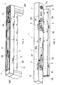
- FIGs. 1A to 1D are diagrammatic views of the device, generally indicated with reference numeral (1), applied on a "door with sliding panel abut against jambs", which comprises only one panel (A).
- An opening is obtained in a masonry wall (M), generating a door opening (V) wherein a frame of the door comprising two uprights (MO) is mounted.
- Jambs (S) are mounted on the uprights (MO).
- the panel (A) can have the following three positions:
- the device (1) comprises a first fixed frame (10) adapted to be fixed to the door frame.
- the first fixed frame (10) consists in a box-shaped cross-piece with parallelepiped shape, having suitable length to be housed inside the door opening (V), resting on the uprights (MO) of the door frame.
- the first fixed frame (10) is removably connected to a second frame (20), likewise composed of a cross-piece.
- the second frame (20) has length (L2) lower than length (L1) of the first frame (10).
- the second frame (20) is positioned close to and under the first frame (10).
- the second mobile frame (20) is connected to the first fixed frame (10) with connection means (M1) allowing said second frame (20) to be in retracted position, as shown in Fig. 5B , wherein the panel (A), supported by the device (1), is housed inside the door opening (V) and abut against jambs (S) of the door frame, and an extracted position, as shown in Fig. 5B , wherein the panel (A) is not housed inside the door opening (V) and is separated from the jambs (S) of the door frame.
- connection means (M1) comprise a pair of identical rockers (2).
- Each rocker (2) comprises a first pin (2a) situated on the first frame (10), and a second pin (2b) situated on the second frame (20).
- first frame (10), the second frame (20) and the pair of rockers (2) form an articulated quadrilateral that allows the second frame (20) to roto-translate with respect to the first frame, while always remaining parallel to the first fixed frame.
- the roto-translations of the second frame (20) are guided by guiding means comprising two identical curvilinear guide tracks (3) obtained on the first frame (10), in which second pins (2b) of the rockers (2) are inserted with freedom of sliding.
- the device (1) further comprises means to provide perfect synchronism between the alternate oscillations of the rockers (2).
- each first pin (2a) consists in a revolving shaft with vertical axis, provided with lower end wherein one of the two ends of the rocker (2) is splined, and provided with upper end wherein a toothed pulley (4) is splined, as shown in Fig. 2 .
- the two toothed pulleys (4) are housed inside the first frame (10), which also contains a toothed belt (5) engaged with both toothed pulleys (4), thus ensuring perfect synchronism between oscillations of the two rockers (2).
- Said toothed belt (5) engages also with a third toothed pulley (6), which is also housed inside the first frame (10), confined at one end of the first frame (10).
- Said third pulley (6) is splined to an upper end of a vertical shaft (7), supported by the first frame (10).
- the vertical shaft (7) has an axial hole (7a) (refer to Fig. 3 ), with splined profile, with opening accessible from the bottom.
- the shaft (7) is situated in correspondence of an ending section of the first frame (10), which protrudes from said second frame (20), in view of the fact that the first frame (10) is provided, as mentioned earlier, with length (L1) higher than length (L2) of the second frame (20).
- the first frame (10) has length (L1) such to be housed inside the door opening (V), astride uprights (MO) of the door frame. Therefore, said shaft (7) surmounts one of the uprights (MO) of the door frame, as shown in Fig. 2 .
- the upper section of a vertical return rod (8) is inserted into the opening of the hole (7a) of said shaft (refer to Figs. 3 and 4 ) with prismatic profile.
- the return rod (8) is adapted to be disposed and concealed behind one of the uprights (MO) of the door frame.
- a horizontal arm (9) is applied, ending with a roll (9a) with vertical axis, slidingly inserted into a central groove (SL) (refer to Fig. 1 D) longitudinally obtained along the lower edge (A1) of the panel (A).
- the device (1) comprises a telescopic guide (30) with two or more tracks, for support and handling of the sliding panel (A).
- the last translating track of the telescopic guide (30) is joined with the upper edge (A2) of the panel.
- the second mobile frame (20) acts as support for the first non-translating track of the telescopic guide (30).
- the second frame (20) acts as first non-translating track of the telescopic guide (30). Therefore, the second frame (20) is an integral part of the telescopic guide.
- said second frame (20) comprises a series of idle wheels (32) with horizontal axis, to which an intermediate track (33) is slidingly associated.
- the intermediate track (33) supports a series of idle wheels (34) to which the last translating track (35) of the telescopic guide (30) is slidingly associated; the last track (35) is joined with the panel (A) near the upper edge (A2) of the door.
- a telescopic guide that can be efficaciously used in the device (1) is disclosed in the Italian patent application RM2010A000594 under the name of the Applicant.
- the device (1) also comprises actuator (T) (refer to Fig. 3 ) for decelerated automatic return of the panel (A) during the first opening phase or the last closing phase, i.e. in those two phases in which the panel does not slide parallel to the wall (M), but simply moves inside the door opening (V), respectively moving away from the jambs (S) or moving closer to the jambs (S)
- said actuators (T) consist in a gas spring, composed of a jack with cylinder (40a) hinged under the first frame (10) and stem (40b) hinged above the second frame (20) .
- the first frame (10) remains protected and concealed behind finish bands (F) of the door frame.
- Fig. 6 shows an alternative embodiment of the first frame (10), in which the driving belt (5) is replaced by an opposite pair of racks (5a), meshing with two toothed pulleys (4) and the third toothed pulleys (6).
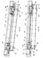
- Figs. 7A , 7A' and 7B shows a second embodiment of the device (1), which uses mobile connection means (M2) between the first frame (10) and the second frame (20), which differ from the connection means (M1) of the first embodiment.
- M2 mobile connection means
- connection means (M2) comprise a pair of identical slides (50) joined with the second frame (20), slidingly coupled within corresponding guide tracks (51) joined with the first frame (10).
- the sliding axis (X) of said slides (50) is horizontal and orthogonal to the panel (A), which is fixed to the second frame (20), after interposition of the telescopic guide (30) (described in the first embodiment and not shown in Figs. 7A and 7B ).
- the telescopic guide (30) allows the panel (A) to make rectilinear alternate travels on a vertical plane, orthogonal to the horizontal sliding axis (X) of the slides (50).
- the second frame (20) supports a shaft (52) with horizontal axis orthogonal to the sliding axis (X) of said slides (50).
- two identical pinions (53) are splined, engaging with corresponding racks (54) joined with the first frame (10) and parallel to the sliding axis (X) of the slides (50).
- this embodiment provides for a return rod (8) with vertical axis, which starts rotating around its vertical axis every time the second mobile frame (20) moves with respect to the first fixed frame (10).
- the return rod (8) is inserted into a revolving bush (55) with vertical axis housed into a suitable seat obtained in the first frame (10).
- the bush (55) has an external toothed ring (56) engaging with a rack (57) joined with the slide (50), so that every travel of the slide (50) corresponds to a simultaneous rotation of said revolving bush (55) around its axis, in clockwise direction or vice versa, according to the direction (forward or backward) of the travel of the slide (50).
- the first frame (10) is provided at its ends with two identical bushes (55), wherein the return rod (8) is selectively inserted according to the opening direction (right or left) of the panel (A).
- the return rod (8) is not provided with circular section, but with at least one facet allowing for insertion into the bush (55) or the shaft (7) of the first embodiment according to the opening direction (right or left) of the panel (A).
- This second embodiment of the device (1) which is shown in Figs. 7A and 7B , is characterized by higher flexibility compared to the first one, in the realization of devices (1) with different lengths, compatible with the width of the door opening (V).
- connection means (M2) are mounted at the two ends of a simple mounting plate, which can have different length from time to time, without requiring any dimensional adjustment of said means (M2), which have therefore standardized shape and dimensions (V).
- Each slide (50) is preferably provided with decelerated automatic return means, which also guarantee the stable stop of the slide in its two opposite stop positions.
- Said means can be gas springs or other equivalent means, of known type and therefore not illustrated herein.
- Figs. 8 to 11 show a third embodiment of the device (1), which uses mobile connection means (M3) between the first frame (10) and the second frame (20), which differ from the connection means (M1 and M2) of the first two embodiments.
- said mobile connection means (M3) comprise a pair of roto-translating plates (60) fixed on the side of the second frame (20) facing towards the door opening (V) and connected to the first fixed frame (10) by means of an eccentric mechanism (E).
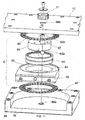
- Fig. 11 is an exploded view of all parts of said eccentric mechanism (E).
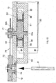
- Fig. 12 shows said eccentric mechanism (E) cut with a vertical plane passing through its axis of rotation.
- said eccentric mechanism (E) comprises:
- Said circular housing (64) consists in a through hole obtained on each plate (60), the lower and upper openings of which are circumscribed by two annular cavities (65) where axial push bearings (66) are housed.
- Said eccentric mechanism (E) and the relevant plate (60) are housed in a compartment (67) obtained in the first fixed frame (10) and provided with front opening for the mobile plate (60) that makes roto-translation motions inside said compartment (67).
- Said compartment (67) is obtained by fixing a sort of frontally open drawer (68) under the first frame (10).
- Said base and top ends (62a and 62b) of the off-centered shaft (62) are inserted into corresponding housings (69a and 69b), respectively obtained on a bottom wall (70) of said drawer (68) and in said first fixed frame (10), as shown in Fig. 11 .
- Said axial push bearings (66) are interposed between the roto-translating plate (60) and the first frame (10), on one side, and between the roto-translating plate (60) and the bottom wall (70) of the drawer (68), on the other side.
- this embodiment provides for a return rod (8) with vertical axis, which starts rotating around its vertical axis every time the second mobile frame (20) moves with respect to the first fixed frame (10).
- the kinematic mechanism used to drive said return rod (8) into rotation every time the second mobile frame (20) moves with respect to the first fixed frame (10) comprises:
- the rod (8) is inserted from below into said bush (74), as shown in Fig. 12 .
- the panel (A) is fixed to the second frame (20) with the interposition of a telescopic guide that allows the panel (A) to make alternate rectilinear travels over a vertical plane.
- Fig. 9 shows the position of the eccentric mechanism (E) when the door is closed.
- the disk (61) is induced and forced to rotate together with the shaft (62), which is constrained to the first fixed frame (10).
- the rotation of the disk (61) causes the movement of the plate (60) that makes a roto-translation with center of rotation on the shaft (62), consequently extracting said second mobile frame (20) from the door opening (V), as shown in Fig. 10 , which also shows the different position of the eccentric mechanism (E) compared to Fig. 9 .
- Such a roto-translating motion of the plate (60) corresponds to a simultaneous synchronized rotation of the return rod (8), given the fact that the pinion (71), revolving jointly with the shaft (62), drives into rotation, by means of the rack (73), the pinion (72) mounted on the bush (74) coupled at the top end of the return rod (8).
- This third embodiment can be motorized easily and inexpensively, by associating the shaft (62) to an electric motor with two directions of rotation, mounted on the first frame (10).
- the device (1) illustrated in the three embodiments shown in the figures comprises two independent parts, which can be separately ordered by the final user and combined together (being possibly already available in the warehouse):
- the handling movements and the relevant guides have a predefined direction. This means that different devices are provided for doors with right-side opening and doors with left-side opening. Moreover, the guide is constrained to the handling device.
Landscapes
- Engineering & Computer Science (AREA)
- Mechanical Engineering (AREA)
- Wing Frames And Configurations (AREA)
- Power-Operated Mechanisms For Wings (AREA)
Claims (15)
- Dispositif (1) pour le support et le déplacement de panneaux coulissants pour portes comprenant :- un premier châssis fixe (10) logé dans un ouverture-porte (V) définie par un châssis de la porte et à cheval de montants (MO) du châssis de la porte ;- un second châssis mobile (20) sous-jacent au premier châssis fixe (10) ;- une coulisse télescopique (30), à deux ou plusieurs rails, interposée entre le second châssis mobile (20) et le panneau (A) de la porte, en correspondance du bord supérieur (A2) du panneau, de manière que le panneau (A) puisse glisser par rapport au second châssis mobile (20) et être supporté par le dispositif (1),- des moyens de liaison mobile (M1, M2, M3) entre le premier châssis (10) et le second châssis (20), de manière que le second châssis (20) puisse se déplacer d'une première position, où le panneau coulissant (A) est logé à l'intérieur de l'ouverture-porte (V) et va en battement contre les intrados (S) du châssis de la porte, et une seconde position, où le panneau coulissant (A) n'est pas logé dans l'ouverture-porte (V) et il est distancié des intrados (S) du châssis de la porte,- au moins une roue pivotante (6; 55 56; 72) à axe vertical, disposée dans ledit premier châssis fixe (10),- une tige de renvoi (8), ayant axe vertical, reliée à ladite roue pivotante (6; 55; 72),- un bras horizontal (9) relié à la tige de renvoi (8) et doté d'un roulement ou d'un patin de coulissement (9a) pivotant à axe vertical, enfilé et coulissant dans une rainure longitudinale (SL) le long du bord inférieur (A1) du panneau (A),- des moyens de synchronisation (5; 5a; 57; 73) qui synchronisent le mouvement des dits moyens de liaison mobile (M1; M2; M3) avec la rotation de ladite roue pivotante (6; 55; 72), de manière à consentir le mouvement synchronisé du bord supérieur (A2) et du bord inférieur (A1) du panneau de la porte.
- Dispositif selon la revendication 1, caractérisé en ce que le second châssis (20) fonctionne en tant que premier rail, non de translation, de la coulisse télescopique (30).
- Dispositif selon l'une des revendications précédentes, caractérisé en ce que lesdits moyens de liaison mobile (M1) comprennent :- une paire de culbuteurs identiques (2) ayant un premier pivot (2a) positionné sur le premier châssis (10) et un second pivot (2b) positionné sur le second châssis (20) ; et- deux guides identiques curvilignes de coulissement (3), réalisées sur le premier châssis (10), dans lesquelles sont enfilés avec liberté de coulissement lesdits seconds pivots (2b) des culbuteurs (2).
- Dispositif selon la revendication précédente, caractérisé en ce qu'il comprend :- deux poulies dentées (4) logées à l'intérieur du premier châssis (10) et reliées à leurs respectifs premiers pivots (2a) des culbuteurs et- une courroie dentée (5) qui s'engage avec les deux poulies dentées (4), en assurant ainsi un synchronisme parfait entre les oscillations des deux culbuteurs (2).
- Dispositif selon la revendication précédente, caractérisé en ce que ladite au moins une roue pivotante (6) reliée à la tige de renvoi (8) est une troisième poulie dentée (6) disposée à une extrémité du premier châssis (10) et lesdits moyens de synchronisation (5) sont ladite courroie dentée (5) qui s'embraye avec ladite troisième poulie dentée (6).
- Dispositif selon les revendication 1 ou 2, caractérisé en ce que lesdits moyens de liaison mobile (M2) comprennent une paire identique de traineaux (50) solidaires au second châssis (20), accrochés de manière coulissante dans des respectifs rails de coulissement (51) solidaires au premier châssis (10).
- Dispositif selon la revendication précédente, caractérisé en ce qu'il comprend :- un arbre horizontal (52) supporté par le second châssis (20) ayant un axe (Y) orthogonal à l'axe horizontal de coulissement (X) desdits traineaux (50) ;- deux crémaillères (54) solidaires au premier châssis (10) et parallèles à l'axe de coulissement (X) des traineaux (50) ; et- deux pignons (53) caletés aux deux extrémités du dit arbre (52) et embrayés avec lesdites crémaillères (54).
- Dispositif, selon la revendication précédente, caractérisé en ce que ladite roue pivotante (55) est une douille (55) ayant une bague externe dentée (56) et lesdits moyens de synchronisation (57) sont une crémaillère (57) solidaire avec le traineau (50).
- Dispositif, selon les revendications 1 ou 2, caractérisé en ce que lesdits moyens de liaison mobile (M3) comprennent une paire identique de plaques à translation rotative (60) fixées sur le côté du second châssis (20) tourné vers l'ouverture-porte (V) et reliées au premier châssis fixe (10) moyennant un mécanisme à excentrique (E) comprenant :- un disque (61) qui supporte un arbre hors centre (62), ayant axe vertical, qui présente une extrémité de base (62a) et une extrémité de tête (62b) ;- un roulement radial (63) qui circonscrit le disque (61) ;- un siège circulaire (64) qui accueille ledit roulement radial (63) et qui consiste en un trou passant réalisé sur chaque plaque (60),- deux roulements axiaux de poussée (66) logés dans des respectives cavités annulaires (65) du siège circulaire (64).
- Dispositif, selon la revendication précédente, caractérisé en ce que chaque dispositif à excentrique (E) et la plaque correspondante (60) sont logés dans un espacement (67) réalisé dans le premier châssis fixe (10) et ayant une ouverture frontale de passage pour la plaque mobile (60), qui accomplit des mouvements de translation rotative à l'intérieur de cet espacement (67).
- Dispositif, selon la revendication précédente, caractérisé en ce que en-dessous du premier châssis fixe (10) on installe un tiroir (68), ouvert frontalement et qui délimite cet espacement (67) et en ce que lesdites extrémités de base et de tête (62a et 62b) de l'arbre hors centre (62) sont enfilées dans des sièges correspondants (69a et 69b), réalisés respectivement sur une paroi de fond (70) du dit tiroir (68) et sur le premier châssis fixe (10).
- Dispositif, selon la revendication précédente, caractérisé en ce qu'il comprend un premier pignon (71) fixé sur l'extrémité de tête (62b) de l'arbre excentrique (62) ; où ladite roue pivotante (72) est un deuxième pignon (72), fixé sur l'extrémité de tête d'une douille (74) logée et pivotante dans un siège prévu à cet effet réalisé sur le premier châssis (10) ; et lesdits moyens de synchronisation (73) sont une crémaillère (73) qui s'embraye avec lesdits premier pignon (70) et second pignon (71).
- Dispositif selon l'une quelconque des revendications de 9 à 12, caractérisé en ce qu'il comprend un moteur électrique à deux directions de rotation, monté sur le premier châssis (10) et relié au dit arbre hors centre (62).
- Dispositif selon l'une quelconque des revendications de 2 à 13, caractérisé en ce que ledit second châssis (20) supporte une série de roues folles (32), ayant axe horizontal, auxquelles est associé de manière coulissante un rail intermédiaire (33) qui supporte une série de petites roues folles (34), auxquelles est associé le dernier rail coulissant (35) de la coulisse télescopique (30), fixé au panneau coulissant (A) en proximité du bord supérieur (A2) du panneau.
- Dispositif selon l'une quelconque des revendications précédentes, caractérisé en ce que ladite roue pivotante (6; 55; 72) à axe vertical comprend un trou (7a) ayant profil rainure et ladite tige de renvoi (8) comprend au moins un segment d'extrémité ayant profil prismatique qui se couple dans ledit trou (7a) ayant profil rainuré.
Applications Claiming Priority (1)
| Application Number | Priority Date | Filing Date | Title |
|---|---|---|---|
| ITAN20120016 | 2012-03-02 |
Publications (2)
| Publication Number | Publication Date |
|---|---|
| EP2634340A1 EP2634340A1 (fr) | 2013-09-04 |
| EP2634340B1 true EP2634340B1 (fr) | 2015-01-14 |
Family
ID=45992585
Family Applications (1)
| Application Number | Title | Priority Date | Filing Date |
|---|---|---|---|
| EP20130156308 Active EP2634340B1 (fr) | 2012-03-02 | 2013-02-22 | Dispositif de support et de manipulation de panneaux coulissants de portes |
Country Status (3)
| Country | Link |
|---|---|
| EP (1) | EP2634340B1 (fr) |
| ES (1) | ES2534977T3 (fr) |
| IT (1) | ITAN20130016A1 (fr) |
Families Citing this family (2)
| Publication number | Priority date | Publication date | Assignee | Title |
|---|---|---|---|---|
| EP4001562A1 (fr) * | 2020-11-13 | 2022-05-25 | Nabtesco Corporation | Dispositif de porte encastrée |
| CN113133645B (zh) * | 2021-05-31 | 2022-01-21 | 东山县东隆金属设备制造有限公司 | 一种改进型蒸煮炉 |
Family Cites Families (5)
| Publication number | Priority date | Publication date | Assignee | Title |
|---|---|---|---|---|
| DE3343366A1 (de) | 1983-11-30 | 1985-06-05 | Schaumburg-Lippische Baubeschlag-Fabrik W. Hautau GmbH, 3061 Helpsen | Beschlag fuer den schiebefluegel von fenstern oder tueren |
| DE3610775A1 (de) | 1986-03-29 | 1987-10-08 | Audi Ag | Drehmomentuebertragende verbindung |
| DE3619775A1 (de) * | 1986-06-12 | 1987-12-17 | Heinz Hanewinkel | Schiebetuerschrank |
| DE102004005170B4 (de) | 2004-02-02 | 2006-06-01 | Klima-Delta Gmbh | Fenster |
| DE202011002810U1 (de) | 2011-02-16 | 2011-06-09 | Inter Ikea Systems B.V. | Mechanismus für Schiebetür |
-
2013
- 2013-01-31 IT ITAN20130016 patent/ITAN20130016A1/it unknown
- 2013-02-22 EP EP20130156308 patent/EP2634340B1/fr active Active
- 2013-02-22 ES ES13156308.2T patent/ES2534977T3/es active Active
Also Published As
| Publication number | Publication date |
|---|---|
| EP2634340A1 (fr) | 2013-09-04 |
| ES2534977T3 (es) | 2015-04-30 |
| ITAN20130016A1 (it) | 2013-09-03 |
Similar Documents
| Publication | Publication Date | Title |
|---|---|---|
| JP6006728B2 (ja) | 横方向に引かれる扉、特に家具の一部に設ける装置 | |
| JP6258344B2 (ja) | 引戸の開閉装置 | |
| EP2032791B1 (fr) | Armoire ou article mobilier similaire comprenant une porte pliante coulissante | |
| TWI647371B (zh) | 用於門扇的引導系統 | |
| JP2014500417A5 (fr) | ||
| RU2337600C2 (ru) | Выдвижной ящик | |
| TWI726223B (zh) | 用於移動可移動家具部件的配置以及具有該配置之家具 | |
| EP2634340B1 (fr) | Dispositif de support et de manipulation de panneaux coulissants de portes | |
| EP2021567B1 (fr) | Meuble suspendu doté de portes basculantes | |
| JP2016520742A (ja) | スライドドアのための機能的フィティング | |
| JP2016520742A5 (fr) | ||
| US20100275822A1 (en) | Hinge | |
| CN112689697B (zh) | 门板-框架组件和具有所述门板-框架组件的橱柜 | |
| EP2801686B1 (fr) | Dispositif d'ouverture pour portes coplanaires | |
| WO2024245281A1 (fr) | Structure d'ouverture/fermeture de porte de réfrigérateur et réfrigérateur | |
| KR102453024B1 (ko) | 조립 및 현장시공이 용이한 댐핑장치를 갖는 동시 개폐형 여닫이 도어 | |
| KR200488569Y1 (ko) | 여닫이와 미닫이를 겸한 장롱 도어 개폐장치 | |
| RU2826024C2 (ru) | Способ изготовления вертикальной направляющей для предмета мебели и предмет мебели | |
| CN113273858A (zh) | 一种穿衣镜的收纳结构 | |
| JP4152867B2 (ja) | キャビネットにおける引戸の戸閉装置。 | |
| ITUB20154078A1 (it) | Sistema per lo scorrimento e la rotazione, selettivi, di una anta e mobile provvisto di tale sistema. | |
| JP4321973B2 (ja) | 扉収納機構 | |
| RU2775210C2 (ru) | Панель предмета мебели, имеющая шарнир, и предмет мебели, имеющий такую панель предмета мебели | |
| CN110685553A (zh) | 一种家具弹性平移开闭结构 | |
| CN118997630A (zh) | 一种暗藏轨道式推拉门 |
Legal Events
| Date | Code | Title | Description |
|---|---|---|---|
| PUAI | Public reference made under article 153(3) epc to a published international application that has entered the european phase |
Free format text: ORIGINAL CODE: 0009012 |
|
| AK | Designated contracting states |
Kind code of ref document: A1 Designated state(s): AL AT BE BG CH CY CZ DE DK EE ES FI FR GB GR HR HU IE IS IT LI LT LU LV MC MK MT NL NO PL PT RO RS SE SI SK SM TR |
|
| AX | Request for extension of the european patent |
Extension state: BA ME |
|
| 17P | Request for examination filed |
Effective date: 20140224 |
|
| RBV | Designated contracting states (corrected) |
Designated state(s): AL AT BE BG CH CY CZ DE DK EE ES FI FR GB GR HR HU IE IS IT LI LT LU LV MC MK MT NL NO PL PT RO RS SE SI SK SM TR |
|
| RIC1 | Information provided on ipc code assigned before grant |
Ipc: E05D 15/10 20060101AFI20140717BHEP |
|
| GRAP | Despatch of communication of intention to grant a patent |
Free format text: ORIGINAL CODE: EPIDOSNIGR1 |
|
| INTG | Intention to grant announced |
Effective date: 20140827 |
|
| GRAS | Grant fee paid |
Free format text: ORIGINAL CODE: EPIDOSNIGR3 |
|
| GRAA | (expected) grant |
Free format text: ORIGINAL CODE: 0009210 |
|
| AK | Designated contracting states |
Kind code of ref document: B1 Designated state(s): AL AT BE BG CH CY CZ DE DK EE ES FI FR GB GR HR HU IE IS IT LI LT LU LV MC MK MT NL NO PL PT RO RS SE SI SK SM TR |
|
| REG | Reference to a national code |
Ref country code: GB Ref legal event code: FG4D |
|
| REG | Reference to a national code |
Ref country code: CH Ref legal event code: EP |
|
| REG | Reference to a national code |
Ref country code: IE Ref legal event code: FG4D |
|
| REG | Reference to a national code |
Ref country code: AT Ref legal event code: REF Ref document number: 707167 Country of ref document: AT Kind code of ref document: T Effective date: 20150215 |
|
| REG | Reference to a national code |
Ref country code: DE Ref legal event code: R096 Ref document number: 602013000820 Country of ref document: DE Effective date: 20150226 |
|
| REG | Reference to a national code |
Ref country code: CH Ref legal event code: NV Representative=s name: OFFICE ERNEST T. FREYLINGER S.A., CH |
|
| REG | Reference to a national code |
Ref country code: ES Ref legal event code: FG2A Ref document number: 2534977 Country of ref document: ES Kind code of ref document: T3 Effective date: 20150430 |
|
| REG | Reference to a national code |
Ref country code: NL Ref legal event code: VDEP Effective date: 20150114 |
|
| REG | Reference to a national code |
Ref country code: AT Ref legal event code: MK05 Ref document number: 707167 Country of ref document: AT Kind code of ref document: T Effective date: 20150114 |
|
| REG | Reference to a national code |
Ref country code: LT Ref legal event code: MG4D |
|
| PG25 | Lapsed in a contracting state [announced via postgrant information from national office to epo] |
Ref country code: BE Free format text: LAPSE BECAUSE OF NON-PAYMENT OF DUE FEES Effective date: 20150228 |
|
| PG25 | Lapsed in a contracting state [announced via postgrant information from national office to epo] |
Ref country code: SE Free format text: LAPSE BECAUSE OF FAILURE TO SUBMIT A TRANSLATION OF THE DESCRIPTION OR TO PAY THE FEE WITHIN THE PRESCRIBED TIME-LIMIT Effective date: 20150114 Ref country code: HR Free format text: LAPSE BECAUSE OF FAILURE TO SUBMIT A TRANSLATION OF THE DESCRIPTION OR TO PAY THE FEE WITHIN THE PRESCRIBED TIME-LIMIT Effective date: 20150114 Ref country code: FI Free format text: LAPSE BECAUSE OF FAILURE TO SUBMIT A TRANSLATION OF THE DESCRIPTION OR TO PAY THE FEE WITHIN THE PRESCRIBED TIME-LIMIT Effective date: 20150114 Ref country code: NO Free format text: LAPSE BECAUSE OF FAILURE TO SUBMIT A TRANSLATION OF THE DESCRIPTION OR TO PAY THE FEE WITHIN THE PRESCRIBED TIME-LIMIT Effective date: 20150414 Ref country code: LT Free format text: LAPSE BECAUSE OF FAILURE TO SUBMIT A TRANSLATION OF THE DESCRIPTION OR TO PAY THE FEE WITHIN THE PRESCRIBED TIME-LIMIT Effective date: 20150114 Ref country code: BG Free format text: LAPSE BECAUSE OF FAILURE TO SUBMIT A TRANSLATION OF THE DESCRIPTION OR TO PAY THE FEE WITHIN THE PRESCRIBED TIME-LIMIT Effective date: 20150414 |
|
| PG25 | Lapsed in a contracting state [announced via postgrant information from national office to epo] |
Ref country code: GR Free format text: LAPSE BECAUSE OF FAILURE TO SUBMIT A TRANSLATION OF THE DESCRIPTION OR TO PAY THE FEE WITHIN THE PRESCRIBED TIME-LIMIT Effective date: 20150415 Ref country code: LV Free format text: LAPSE BECAUSE OF FAILURE TO SUBMIT A TRANSLATION OF THE DESCRIPTION OR TO PAY THE FEE WITHIN THE PRESCRIBED TIME-LIMIT Effective date: 20150114 Ref country code: AT Free format text: LAPSE BECAUSE OF FAILURE TO SUBMIT A TRANSLATION OF THE DESCRIPTION OR TO PAY THE FEE WITHIN THE PRESCRIBED TIME-LIMIT Effective date: 20150114 Ref country code: PL Free format text: LAPSE BECAUSE OF FAILURE TO SUBMIT A TRANSLATION OF THE DESCRIPTION OR TO PAY THE FEE WITHIN THE PRESCRIBED TIME-LIMIT Effective date: 20150114 Ref country code: RS Free format text: LAPSE BECAUSE OF FAILURE TO SUBMIT A TRANSLATION OF THE DESCRIPTION OR TO PAY THE FEE WITHIN THE PRESCRIBED TIME-LIMIT Effective date: 20150114 Ref country code: NL Free format text: LAPSE BECAUSE OF FAILURE TO SUBMIT A TRANSLATION OF THE DESCRIPTION OR TO PAY THE FEE WITHIN THE PRESCRIBED TIME-LIMIT Effective date: 20150114 Ref country code: IS Free format text: LAPSE BECAUSE OF FAILURE TO SUBMIT A TRANSLATION OF THE DESCRIPTION OR TO PAY THE FEE WITHIN THE PRESCRIBED TIME-LIMIT Effective date: 20150514 |
|
| REG | Reference to a national code |
Ref country code: DE Ref legal event code: R097 Ref document number: 602013000820 Country of ref document: DE |
|
| PG25 | Lapsed in a contracting state [announced via postgrant information from national office to epo] |
Ref country code: RO Free format text: LAPSE BECAUSE OF FAILURE TO SUBMIT A TRANSLATION OF THE DESCRIPTION OR TO PAY THE FEE WITHIN THE PRESCRIBED TIME-LIMIT Effective date: 20150114 Ref country code: DK Free format text: LAPSE BECAUSE OF FAILURE TO SUBMIT A TRANSLATION OF THE DESCRIPTION OR TO PAY THE FEE WITHIN THE PRESCRIBED TIME-LIMIT Effective date: 20150114 Ref country code: SK Free format text: LAPSE BECAUSE OF FAILURE TO SUBMIT A TRANSLATION OF THE DESCRIPTION OR TO PAY THE FEE WITHIN THE PRESCRIBED TIME-LIMIT Effective date: 20150114 Ref country code: CZ Free format text: LAPSE BECAUSE OF FAILURE TO SUBMIT A TRANSLATION OF THE DESCRIPTION OR TO PAY THE FEE WITHIN THE PRESCRIBED TIME-LIMIT Effective date: 20150114 Ref country code: MC Free format text: LAPSE BECAUSE OF FAILURE TO SUBMIT A TRANSLATION OF THE DESCRIPTION OR TO PAY THE FEE WITHIN THE PRESCRIBED TIME-LIMIT Effective date: 20150114 Ref country code: EE Free format text: LAPSE BECAUSE OF FAILURE TO SUBMIT A TRANSLATION OF THE DESCRIPTION OR TO PAY THE FEE WITHIN THE PRESCRIBED TIME-LIMIT Effective date: 20150114 |
|
| REG | Reference to a national code |
Ref country code: IE Ref legal event code: MM4A |
|
| PLBE | No opposition filed within time limit |
Free format text: ORIGINAL CODE: 0009261 |
|
| STAA | Information on the status of an ep patent application or granted ep patent |
Free format text: STATUS: NO OPPOSITION FILED WITHIN TIME LIMIT |
|
| 26N | No opposition filed |
Effective date: 20151015 |
|
| PG25 | Lapsed in a contracting state [announced via postgrant information from national office to epo] |
Ref country code: IE Free format text: LAPSE BECAUSE OF NON-PAYMENT OF DUE FEES Effective date: 20150222 |
|
| REG | Reference to a national code |
Ref country code: FR Ref legal event code: PLFP Year of fee payment: 4 |
|
| PG25 | Lapsed in a contracting state [announced via postgrant information from national office to epo] |
Ref country code: SI Free format text: LAPSE BECAUSE OF FAILURE TO SUBMIT A TRANSLATION OF THE DESCRIPTION OR TO PAY THE FEE WITHIN THE PRESCRIBED TIME-LIMIT Effective date: 20150114 |
|
| PG25 | Lapsed in a contracting state [announced via postgrant information from national office to epo] |
Ref country code: BE Free format text: LAPSE BECAUSE OF FAILURE TO SUBMIT A TRANSLATION OF THE DESCRIPTION OR TO PAY THE FEE WITHIN THE PRESCRIBED TIME-LIMIT Effective date: 20150114 |
|
| PG25 | Lapsed in a contracting state [announced via postgrant information from national office to epo] |
Ref country code: MT Free format text: LAPSE BECAUSE OF FAILURE TO SUBMIT A TRANSLATION OF THE DESCRIPTION OR TO PAY THE FEE WITHIN THE PRESCRIBED TIME-LIMIT Effective date: 20150114 |
|
| REG | Reference to a national code |
Ref country code: FR Ref legal event code: PLFP Year of fee payment: 5 |
|
| PG25 | Lapsed in a contracting state [announced via postgrant information from national office to epo] |
Ref country code: HU Free format text: LAPSE BECAUSE OF FAILURE TO SUBMIT A TRANSLATION OF THE DESCRIPTION OR TO PAY THE FEE WITHIN THE PRESCRIBED TIME-LIMIT; INVALID AB INITIO Effective date: 20130222 |
|
| PG25 | Lapsed in a contracting state [announced via postgrant information from national office to epo] |
Ref country code: CY Free format text: LAPSE BECAUSE OF FAILURE TO SUBMIT A TRANSLATION OF THE DESCRIPTION OR TO PAY THE FEE WITHIN THE PRESCRIBED TIME-LIMIT Effective date: 20150114 |
|
| PG25 | Lapsed in a contracting state [announced via postgrant information from national office to epo] |
Ref country code: TR Free format text: LAPSE BECAUSE OF FAILURE TO SUBMIT A TRANSLATION OF THE DESCRIPTION OR TO PAY THE FEE WITHIN THE PRESCRIBED TIME-LIMIT Effective date: 20150114 |
|
| PG25 | Lapsed in a contracting state [announced via postgrant information from national office to epo] |
Ref country code: LU Free format text: LAPSE BECAUSE OF NON-PAYMENT OF DUE FEES Effective date: 20150222 |
|
| REG | Reference to a national code |
Ref country code: FR Ref legal event code: PLFP Year of fee payment: 6 |
|
| PG25 | Lapsed in a contracting state [announced via postgrant information from national office to epo] |
Ref country code: SM Free format text: LAPSE BECAUSE OF FAILURE TO SUBMIT A TRANSLATION OF THE DESCRIPTION OR TO PAY THE FEE WITHIN THE PRESCRIBED TIME-LIMIT Effective date: 20150114 |
|
| PG25 | Lapsed in a contracting state [announced via postgrant information from national office to epo] |
Ref country code: PT Free format text: LAPSE BECAUSE OF FAILURE TO SUBMIT A TRANSLATION OF THE DESCRIPTION OR TO PAY THE FEE WITHIN THE PRESCRIBED TIME-LIMIT Effective date: 20150114 Ref country code: MK Free format text: LAPSE BECAUSE OF FAILURE TO SUBMIT A TRANSLATION OF THE DESCRIPTION OR TO PAY THE FEE WITHIN THE PRESCRIBED TIME-LIMIT Effective date: 20150114 |
|
| PG25 | Lapsed in a contracting state [announced via postgrant information from national office to epo] |
Ref country code: AL Free format text: LAPSE BECAUSE OF FAILURE TO SUBMIT A TRANSLATION OF THE DESCRIPTION OR TO PAY THE FEE WITHIN THE PRESCRIBED TIME-LIMIT Effective date: 20150114 |
|
| PGFP | Annual fee paid to national office [announced via postgrant information from national office to epo] |
Ref country code: GB Payment date: 20200226 Year of fee payment: 8 |
|
| GBPC | Gb: european patent ceased through non-payment of renewal fee |
Effective date: 20210222 |
|
| PG25 | Lapsed in a contracting state [announced via postgrant information from national office to epo] |
Ref country code: GB Free format text: LAPSE BECAUSE OF NON-PAYMENT OF DUE FEES Effective date: 20210222 |
|
| REG | Reference to a national code |
Ref country code: CH Ref legal event code: U11 Free format text: ST27 STATUS EVENT CODE: U-0-0-U10-U11 (AS PROVIDED BY THE NATIONAL OFFICE) Effective date: 20260301 |
|
| PGFP | Annual fee paid to national office [announced via postgrant information from national office to epo] |
Ref country code: ES Payment date: 20260317 Year of fee payment: 14 |
|
| PGFP | Annual fee paid to national office [announced via postgrant information from national office to epo] |
Ref country code: DE Payment date: 20260220 Year of fee payment: 14 |
|
| PGFP | Annual fee paid to national office [announced via postgrant information from national office to epo] |
Ref country code: IT Payment date: 20260120 Year of fee payment: 14 |
|
| PGFP | Annual fee paid to national office [announced via postgrant information from national office to epo] |
Ref country code: FR Payment date: 20260227 Year of fee payment: 14 |
|
| PGFP | Annual fee paid to national office [announced via postgrant information from national office to epo] |
Ref country code: CH Payment date: 20260301 Year of fee payment: 14 |