EP2634366B1 - Pompe à vis à broche double dans une construction à simple flux - Google Patents
Pompe à vis à broche double dans une construction à simple flux Download PDFInfo
- Publication number
- EP2634366B1 EP2634366B1 EP13000395.7A EP13000395A EP2634366B1 EP 2634366 B1 EP2634366 B1 EP 2634366B1 EP 13000395 A EP13000395 A EP 13000395A EP 2634366 B1 EP2634366 B1 EP 2634366B1
- Authority
- EP
- European Patent Office
- Prior art keywords
- section
- pump
- gear
- fastening element
- shaft
- Prior art date
- Legal status (The legal status is an assumption and is not a legal conclusion. Google has not performed a legal analysis and makes no representation as to the accuracy of the status listed.)
- Active
Links
Images




Classifications
-
- F—MECHANICAL ENGINEERING; LIGHTING; HEATING; WEAPONS; BLASTING
- F04—POSITIVE - DISPLACEMENT MACHINES FOR LIQUIDS; PUMPS FOR LIQUIDS OR ELASTIC FLUIDS
- F04C—ROTARY-PISTON, OR OSCILLATING-PISTON, POSITIVE-DISPLACEMENT MACHINES FOR LIQUIDS; ROTARY-PISTON, OR OSCILLATING-PISTON, POSITIVE-DISPLACEMENT PUMPS
- F04C2/00—Rotary-piston machines or pumps
-
- F—MECHANICAL ENGINEERING; LIGHTING; HEATING; WEAPONS; BLASTING
- F01—MACHINES OR ENGINES IN GENERAL; ENGINE PLANTS IN GENERAL; STEAM ENGINES
- F01C—ROTARY-PISTON OR OSCILLATING-PISTON MACHINES OR ENGINES
- F01C17/00—Arrangements for drive of co-operating members, e.g. for rotary piston and casing
- F01C17/02—Arrangements for drive of co-operating members, e.g. for rotary piston and casing of toothed-gearing type
-
- F—MECHANICAL ENGINEERING; LIGHTING; HEATING; WEAPONS; BLASTING
- F01—MACHINES OR ENGINES IN GENERAL; ENGINE PLANTS IN GENERAL; STEAM ENGINES
- F01C—ROTARY-PISTON OR OSCILLATING-PISTON MACHINES OR ENGINES
- F01C21/00—Component parts, details or accessories not provided for in groups F01C1/00 - F01C20/00
- F01C21/10—Outer members for co-operation with rotary pistons; Casings
-
- F—MECHANICAL ENGINEERING; LIGHTING; HEATING; WEAPONS; BLASTING
- F04—POSITIVE - DISPLACEMENT MACHINES FOR LIQUIDS; PUMPS FOR LIQUIDS OR ELASTIC FLUIDS
- F04C—ROTARY-PISTON, OR OSCILLATING-PISTON, POSITIVE-DISPLACEMENT MACHINES FOR LIQUIDS; ROTARY-PISTON, OR OSCILLATING-PISTON, POSITIVE-DISPLACEMENT PUMPS
- F04C15/00—Component parts, details or accessories of machines, pumps or pumping installations, not provided for in groups F04C2/00 - F04C14/00
- F04C15/0057—Driving elements, brakes, couplings, transmission specially adapted for machines or pumps
- F04C15/0061—Means for transmitting movement from the prime mover to driven parts of the pump, e.g. clutches, couplings, transmissions
-
- F—MECHANICAL ENGINEERING; LIGHTING; HEATING; WEAPONS; BLASTING
- F04—POSITIVE - DISPLACEMENT MACHINES FOR LIQUIDS; PUMPS FOR LIQUIDS OR ELASTIC FLUIDS
- F04C—ROTARY-PISTON, OR OSCILLATING-PISTON, POSITIVE-DISPLACEMENT MACHINES FOR LIQUIDS; ROTARY-PISTON, OR OSCILLATING-PISTON, POSITIVE-DISPLACEMENT PUMPS
- F04C2/00—Rotary-piston machines or pumps
- F04C2/08—Rotary-piston machines or pumps of intermeshing-engagement type, i.e. with engagement of co-operating members similar to that of toothed gearing
- F04C2/12—Rotary-piston machines or pumps of intermeshing-engagement type, i.e. with engagement of co-operating members similar to that of toothed gearing of other than internal-axis type
- F04C2/14—Rotary-piston machines or pumps of intermeshing-engagement type, i.e. with engagement of co-operating members similar to that of toothed gearing of other than internal-axis type with toothed rotary pistons
- F04C2/16—Rotary-piston machines or pumps of intermeshing-engagement type, i.e. with engagement of co-operating members similar to that of toothed gearing of other than internal-axis type with toothed rotary pistons with helical teeth, e.g. chevron-shaped, screw type
-
- F—MECHANICAL ENGINEERING; LIGHTING; HEATING; WEAPONS; BLASTING
- F04—POSITIVE - DISPLACEMENT MACHINES FOR LIQUIDS; PUMPS FOR LIQUIDS OR ELASTIC FLUIDS
- F04C—ROTARY-PISTON, OR OSCILLATING-PISTON, POSITIVE-DISPLACEMENT MACHINES FOR LIQUIDS; ROTARY-PISTON, OR OSCILLATING-PISTON, POSITIVE-DISPLACEMENT PUMPS
- F04C2230/00—Manufacture
- F04C2230/60—Assembly methods
- F04C2230/601—Adjustment
-
- F—MECHANICAL ENGINEERING; LIGHTING; HEATING; WEAPONS; BLASTING
- F04—POSITIVE - DISPLACEMENT MACHINES FOR LIQUIDS; PUMPS FOR LIQUIDS OR ELASTIC FLUIDS
- F04C—ROTARY-PISTON, OR OSCILLATING-PISTON, POSITIVE-DISPLACEMENT MACHINES FOR LIQUIDS; ROTARY-PISTON, OR OSCILLATING-PISTON, POSITIVE-DISPLACEMENT PUMPS
- F04C2230/00—Manufacture
- F04C2230/80—Repairing methods
-
- F—MECHANICAL ENGINEERING; LIGHTING; HEATING; WEAPONS; BLASTING
- F04—POSITIVE - DISPLACEMENT MACHINES FOR LIQUIDS; PUMPS FOR LIQUIDS OR ELASTIC FLUIDS
- F04C—ROTARY-PISTON, OR OSCILLATING-PISTON, POSITIVE-DISPLACEMENT MACHINES FOR LIQUIDS; ROTARY-PISTON, OR OSCILLATING-PISTON, POSITIVE-DISPLACEMENT PUMPS
- F04C2240/00—Components
- F04C2240/60—Shafts
-
- F—MECHANICAL ENGINEERING; LIGHTING; HEATING; WEAPONS; BLASTING
- F04—POSITIVE - DISPLACEMENT MACHINES FOR LIQUIDS; PUMPS FOR LIQUIDS OR ELASTIC FLUIDS
- F04C—ROTARY-PISTON, OR OSCILLATING-PISTON, POSITIVE-DISPLACEMENT MACHINES FOR LIQUIDS; ROTARY-PISTON, OR OSCILLATING-PISTON, POSITIVE-DISPLACEMENT PUMPS
- F04C2270/00—Control; Monitoring or safety arrangements
- F04C2270/16—Wear
-
- F—MECHANICAL ENGINEERING; LIGHTING; HEATING; WEAPONS; BLASTING
- F04—POSITIVE - DISPLACEMENT MACHINES FOR LIQUIDS; PUMPS FOR LIQUIDS OR ELASTIC FLUIDS
- F04C—ROTARY-PISTON, OR OSCILLATING-PISTON, POSITIVE-DISPLACEMENT MACHINES FOR LIQUIDS; ROTARY-PISTON, OR OSCILLATING-PISTON, POSITIVE-DISPLACEMENT PUMPS
- F04C2270/00—Control; Monitoring or safety arrangements
- F04C2270/17—Tolerance; Play; Gap
Definitions
- the invention relates to a two-spindle screw pump in a single-flow design with a pump housing which has a pump section, a bearing section and a gear section with a gear room, the bearing section and the pump section being designed separately from one another, with a delivery housing part as part of the pump section, in which two Shafts arranged conveyor screws with flanks are provided, the shafts being mounted in the bearing section and extending into the gear section, with gears arranged on the shafts in the gear section, by means of which the shafts are rotationally coupled, with a fastening element arranged on the shaft in operative connection with these Establishing a holding connection between the shaft and the gear, the fastening element and the gear having corresponding bores via which a holding connection can be established between the gear and the fastening element via a locking element, the screw spindle pump being mountable on a drive module.
- the conveyor screws arranged on the shafts are fastened with a defined clearance between the flanks (backlash).
- Such a pump structure is known from DE 20 2009 014 604 U1 and WO 2004 053 333 A1 . These pumps are particularly characterized by product-friendly operation and the associated low wear. There are no connections between such pumps and a drive module via a gearbox EP 0 096 666 A1 known.
- EP 1 054 160 A1 An alternative setting option for the backlash is available EP 1 054 160 A1 shown.
- the rotor shafts are each driven by their own electric motors.
- the angular positions of the shafts are determined using resolvers, which are used to electronically synchronize the rotors.
- the object of the invention is to improve the aforementioned pump of the preamble in such a way that simpler and less time-consuming maintenance or readjustment can be carried out.
- the holes in the fastening element are designed in such a way that the gear and the fastening element can be rotated relative to one another, so that a distance between the flanks of the delivery screws can be adjusted, and that an opening is provided on the gear section of the pump housing, so that the opening with a detachable cover is provided, that the opening is arranged in such a way that the cover is detachable in the mounted state of the spindle pump when the screw spindle pump is mounted on the drive module, that the gear room for adjusting the backlash of the delivery screws can be reached with the necessary tools, and that the holes in the fastening element are provided as an elongated hole in the circumferential direction with a center line with a constant radius, in which the locking element is displaceable in the inserted but not locked state, and that the length of the elongated hole in the circumferential direction is provided such that its When moving the locking element in the slot, the end points must at least match the contact points of the flanks of the conveyor screws.
- the opening in the housing By providing the opening in the housing, it is possible to significantly reduce the time required for spindle readjustment because it is no longer necessary to dismantle the gear housing to expose the gear chamber and it is also not necessary to dismantle the drive module.
- the maintenance and adjustability of the spindle pump are improved by the fact that it is possible to adjust the entire backlash of the delivery screws by providing the elongated hole. Previously it was necessary that the gear wheel had to be removed from the shaft and repositioned in a twisted manner in order to be able to adjust the backlash adequately. This setting effort is thereby significantly reduced.
- a further teaching of the invention provides that the fastening element with the elongated holes is only provided on one shaft. This takes into account the fact that it has been found that it is sufficient to simply adjust one shaft while the other shaft is constantly mounted.
- a further teaching of the invention provides that there is a hydraulic separation between the pump section and the bearing section, preferably via a mechanical seal and/or that there is a spatial separation between the bearing section and the gear section. These spatial separations have proven to be particularly advantageous with regard to the adjustability of the backlash and the bearing.
- the fastening element has a socket section for sliding onto the shaft, the socket section preferably having a receiving section for the gear, and/or the shaft and the socket section having a groove for receiving a key to produce a rotationally effective connection between the shaft and have fastening element.
- This embodiment element represents a cost-effective and particularly maintenance-friendly embodiment of the invention.
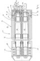
- Fig. 1a and Fig. 1b show a sectional view in plan view of a spindle pump 10 according to the invention.
- the spindle pump 10 has a housing 11 which has a pump section 12, a bearing section 13 and a gear section 14. These are spatially and hydraulically separated from each other.
- the spindle pump 10 comprises a driven shaft 15 and a driven shaft 16.
- a delivery screw 17 is arranged on the driven shaft 15 and a delivery screw 18 is arranged on the driven shaft 16, which are in engagement.
- a needle bearing 19 and a roller bearing 20 are provided in the bearing section 13, so that the shafts are mounted in external bearings outside the pump section 12.
- the shaft ends 22, 23 are located in the gear room 21.
- the shaft end 22 of the driven shaft 15 extends out of the housing 11 and has a connection 24 for a drive unit 49 there.
- On the driven shaft is a gear 26 is arranged. The teeth of the gears 25, 26 are in meshing engagement.
- a fastening element 27 is arranged on the shaft end 23 of the driven shaft 16.
- the fastening element 27 has a socket section 28 and a flange section 29.
- the outside of the socket section 28 is also a receiving surface 30 for the gear 26.
- a key 31 is inserted into a groove (not shown) in the shaft end 23 and in the fastening element 27, via which a rotary connection between the shaft 16 and the fastening element 27 is established.
- a hexagonal screw 33 is screwed into a hole (not shown) in the end face 32 of the shaft end 23, with which a tension washer 34 is screwed against a seat 35 on the fastening element 27. As a result, the fastening element 27 is connected to the shaft end 23 in a locking manner.
- the flange section 29 has a bore 36.
- the gear 26 has a corresponding bore 37, which can be designed as a through bore or as a hole bore.
- a thread (not shown) is arranged in the bore 37.
- a hexagonal screw 38 is screwed into this thread, whereby the flange section 29 of the fastening element 27 is locked with the gear 26.
- Fig. 2 a sectional view through the gear section 14 is shown.
- the meshing gears 25, 26 can be seen.
- the fastening element 27 with its flange section 29 is shown on the gear 26.
- the clamping disk 34 is mounted in the seat 35 of the flange section 29 via the hexagonal screw 33.
- the bore 36 in the flange section 29 is designed as an elongated hole 41.
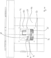
- the gear section 14 has an opening 42 on its upper side, which is connected to the gear section 14 in a holding manner with a cover 43 via hexagonal screws 44.
- Fig. 3 shows a sectional view through the engaged conveyor screws 17, 18.
- the conveyor screws have screw projections 45, each of which has flanks 46.
- the distance between the flanks 46 represents the backlash 47.
- the backlash 47 is therefore adjusted in such a way that the fastening element 27 is arranged in a rotationally fixed manner on the shaft end 23 or the driven shaft 16 via the key 31.
- the tension washer 34 is then screwed into the seat 35 using the hexagon screw 33.
- the gear 26 is already located on the receiving surface 30 of the socket section 28 of the fastening element 27 and is in engagement with the gear 25 of the driven shaft 15.
- the flange section 29 with the elongated holes 41 located therein is now placed over the bores 37 is arranged in the gear 26 and the hexagon screws 38 are screwed in, with no locking connection between the flange section 29 and the gear 26 being created.
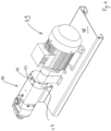
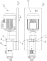
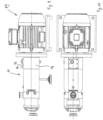
- Fig. 4 to Fig. 7 show an arrangement of the spindle pump 10 on a base plate 48.
- the spindle pump 10 is connected to a drive unit 49.
- Fig. 8 to Fig. 11 show a further embodiment in which the pump has a block design.
- Top views of the gear section 14 are shown without the cover 43 mounted on the opening 42.
- the gear section 14 has a flat section 50 in which holes 51 are arranged around the opening 42 and have a thread (not shown) into which the hexagon screws 44 are screwed.
Landscapes
- Engineering & Computer Science (AREA)
- Mechanical Engineering (AREA)
- General Engineering & Computer Science (AREA)
- Rotary Pumps (AREA)
- Details And Applications Of Rotary Liquid Pumps (AREA)
Claims (6)
- Pompe à vis à doubles broches (10) en version à simple flux pourvue d'un corps de pompe (11) qui comporte une portion formant pompe (12), une portion formant palier (13) et une portion formant transmission (14) pourvue d'un espace de transmission (21), la portion formant palier (13) et la portion formant pompe (12) étant réalisées séparément l'une de l'autre,- comprenant une partie de boîtier de refoulement qui fait partie de la portion formant pompe (12) et dans laquelle sont prévues deux vis de refoulement (17, 18) disposées sur des arbres (15, 16) et pourvues de flancs (46), les arbres (15, 16) étant logés dans la portion formant palier (13) et s'étendant dans la portion formant transmission (14),- comprenant des roues dentées (25, 26) qui sont disposées sur les arbres (15, 16) dans la portion formant transmission (14) et au moyen desquelles les arbres (15, 16) sont accouplés en rotation,- comprenant un élément de fixation (27) qui est disposé sur l'arbre (16), qui est relié fonctionnellement à celui-ci et qui est destiné à établir une liaison de maintien entre l'arbre (16) et la roue dentée (26), l'élément de fixation (27) et la roue dentée (26) comportant des alésages correspondants (36, 37) qui permettent d'établir une liaison de maintien entre la roue dentée (26) et l'élément de fixation (27) par le biais d'un élément de blocage, la pompe à vis (10) pouvant être montée sur un module d'entraînement (47), les alésages (36) dans l'élément de fixation (27) étant conçus de telle sorte que la roue dentée (26) et l'élément de fixation (27) puissent tourner l'un par rapport à l'autre de façon à régler une distance entre les flancs (46) des vis de refoulement (17, 18), caractérisée en ce qu'une ouverture (42) est prévue sur la portion formant transmission (14) du corps de pompe (11), en ce que l'ouverture (42) est munie d'un couvercle amovible (43), en ce que l'ouverture (42) est disposée de telle sorte que le couvercle (43) puisse être détaché si la pompe à vis (10) est montée sur le module d'entraînement (47), en ce que l'espace de transmission (21) peut être atteint avec l'outil nécessaire pour régler le jeu des flancs des vis de refoulement (17, 18) et en ce que les alésages (36) dans l'élément de fixation (27) sont prévus sous la forme d'un trou oblong (41) dans la direction circonférentielle avec une ligne médiane à rayon constant, dans lesquels l'élément de blocage peut coulisser à l'état inséré mais non bloqué, et en ce que la longueur du trou oblong (41) dans la direction circonférentielle est prévue là de telle sorte que les points d'extrémité de celui-ci coïncident au moins avec les points de contact des flancs (46) des vis de refoulement (17, 18) lorsque l'élément de blocage coulisse dans le trou oblong (41).
- Pompe à broches (10) selon la revendication 1, caractérisée en ce que l'élément de fixation (27) est pourvu des trous oblongs (41) seulement sur un arbre (16) .
- Pompe (10) selon la revendication 1 ou 2, caractérisée en ce qu'une séparation hydraulique est ménagée entre la portion formant pompe (12) et la portion formant palier (13), de préférence par le biais d'une garniture d'étanchéité mécanique, et/ou en ce qu'une séparation spatiale est ménagée entre la portion formant palier (13) et la portion formant transmission (14).
- Pompe (10) selon l'une des revendications 1 à 3, caractérisée en ce que l'élément de fixation (27) comporte une portion formant douille (28) destinée à coulisser sur l'arbre (16), la portion formant douille (28) comportant de préférence une portion de réception destinée à la roue dentée (26), et/ou l'arbre (16) et la portion formant douille (28) comportant une rainure destinée à recevoir un ressort d'ajustage destiné à établir une liaison fonctionnelle rotative entre l'arbre (16) et l'élément de fixation (27).
- Pompe (10) selon l'une des revendications 1 à 4, caractérisée en ce que les alésages (37) de la roue dentée (26) sont conçus comme forages de trous comportant des portions filetées et/ou en ce qu'un élément de blocage se présentant sous la forme d'une vis et permettant d'établir la liaison de maintien peut être inséré dans l'alésage (37).
- Pompe (10) selon l'une des revendications 1 à 5, caractérisée en ce qu'un alésage, dans lequel un élément de blocage peut être inséré de manière à bloquer l'élément de fixation (27) contre l'arbre, est ménagé dans la tête d'arbre.
Applications Claiming Priority (1)
| Application Number | Priority Date | Filing Date | Title |
|---|---|---|---|
| DE102012001700A DE102012001700B4 (de) | 2012-01-31 | 2012-01-31 | Zweispindelige Schraubenspindelpumpe in einflutiger Bauweise |
Publications (4)
| Publication Number | Publication Date |
|---|---|
| EP2634366A2 EP2634366A2 (fr) | 2013-09-04 |
| EP2634366A3 EP2634366A3 (fr) | 2015-11-18 |
| EP2634366C0 EP2634366C0 (fr) | 2024-02-28 |
| EP2634366B1 true EP2634366B1 (fr) | 2024-02-28 |
Family
ID=47681604
Family Applications (1)
| Application Number | Title | Priority Date | Filing Date |
|---|---|---|---|
| EP13000395.7A Active EP2634366B1 (fr) | 2012-01-31 | 2013-01-28 | Pompe à vis à broche double dans une construction à simple flux |
Country Status (4)
| Country | Link |
|---|---|
| US (1) | US9624925B2 (fr) |
| EP (1) | EP2634366B1 (fr) |
| DE (1) | DE102012001700B4 (fr) |
| ES (1) | ES2974944T3 (fr) |
Families Citing this family (16)
| Publication number | Priority date | Publication date | Assignee | Title |
|---|---|---|---|---|
| DE102014002396A1 (de) | 2014-02-24 | 2015-08-27 | Jung & Co. Gerätebau GmbH | Zweispindelige Schraubenspindelpumpe in einflutiger Bauweise |
| DE202014010877U1 (de) | 2014-02-24 | 2017-01-02 | Jung & Co. Gerätebau GmbH | Zweispindelige Schraubenspindelpumpe in einflutiger Bauweise |
| DE202014010816U1 (de) | 2014-08-11 | 2016-09-21 | Jung & Co. Gerätebau GmbH | Schraubenspindelpumpe mit Dampfsperre |
| USD749138S1 (en) | 2014-12-19 | 2016-02-09 | Q-Pumps S.A. de C.V. | Twin screw pump |
| DE102017007832A1 (de) | 2017-08-22 | 2019-02-28 | Pumpenfabrik Wangen Gmbh | Verfahren zur Herstellung eines Drehkolbens für eine Schraubenspindelpumpe |
| USD896845S1 (en) * | 2018-06-12 | 2020-09-22 | Alfa Laval Corporate Ab | Twin screw pump |
| USD896846S1 (en) * | 2018-06-12 | 2020-09-22 | Alfa Laval Corporate Ab | Twin screw pump |
| JP6766850B2 (ja) * | 2018-08-24 | 2020-10-14 | 株式会社タツノ | 容積型ポンプ |
| CN111082629B (zh) * | 2020-01-10 | 2021-02-19 | 宁波金锐机械有限公司 | 一种单线环绕的无刷马达 |
| DE102020103384B4 (de) | 2020-02-11 | 2025-11-13 | Gardner Denver Deutschland Gmbh | Schraubenverdichter mit einseitig gelagerten Rotoren |
| DE102020124392A1 (de) * | 2020-09-18 | 2022-03-24 | Itt Bornemann Gmbh | Abstandseinstellung für doppelschneckenpumpen |
| USD976962S1 (en) * | 2021-01-19 | 2023-01-31 | Alfa Laval Corporate Ab | Rotary positive-displacement pump |
| USD973722S1 (en) * | 2021-01-19 | 2022-12-27 | Alfa Laval Corporate Ab | Rotary positive displacement pump |
| DE102021113724A1 (de) * | 2021-05-27 | 2022-12-01 | Jung & Co. Gerätebau GmbH | Schraubenspindelpumpe in einflutiger Bauweise |
| DE102024104230A1 (de) | 2024-02-15 | 2025-08-21 | FRISTAM Pumpen Schaumburg GmbH | Verdrängerpumpe mit Synchrongetriebe |
| DE202024100727U1 (de) | 2024-02-15 | 2024-02-29 | FRISTAM Pumpen Schaumburg GmbH | Verdrängerpumpe mit Synchrongetriebe |
Family Cites Families (16)
| Publication number | Priority date | Publication date | Assignee | Title |
|---|---|---|---|---|
| US1805875A (en) * | 1917-02-13 | 1931-05-19 | Jeffrey Mfg Co | Rotary engine |
| US2287716A (en) * | 1941-04-22 | 1942-06-23 | Joseph E Whitfield | Fluid device |
| US2641937A (en) * | 1949-07-15 | 1953-06-16 | Crown Cork & Seal Co | Adjustable torsion shaft in flying shears |
| US2683994A (en) * | 1951-05-17 | 1954-07-20 | Read Standard Corp | Adjusting device |
| US3037396A (en) * | 1959-05-11 | 1962-06-05 | Merrill David Martin | Backlash preventing gears for coupled driven and drive shafts |
| US3057665A (en) * | 1960-06-24 | 1962-10-09 | Warren Pumps Inc | Pump |
| DE2001000A1 (de) * | 1970-01-10 | 1971-07-15 | Allweiler Ag | Einstelleinrichtung an Schraubenspindelpumpen |
| CH613258A5 (fr) * | 1975-09-24 | 1979-09-14 | Suter Fa Alois | |
| SE454202B (sv) * | 1982-06-07 | 1988-04-11 | Atlas Copco Ab | Kompressordrivarrangemang for justering av driftkarakteristika |
| US6027322A (en) * | 1997-10-29 | 2000-02-22 | Coltec Industries Inc | Method and apparatus for adjusting the rotors of a rotary screw compressor |
| ES2187848T3 (es) * | 1998-04-11 | 2003-06-16 | Bornemann J H Gmbh | Maquina que conduce fluidos. |
| EP1061260A1 (fr) * | 1999-05-18 | 2000-12-20 | Sterling Fluid Systems (Germany) GmbH | Machine à déplacement positif pour des fluides compressibles |
| DE10257859C5 (de) * | 2002-12-11 | 2012-03-15 | Joh. Heinr. Bornemann Gmbh | Schraubenspindelpumpe |
| WO2006087038A1 (fr) * | 2005-02-16 | 2006-08-24 | Ateliers Busch Sa | Machine rotative volumétriques avec rotors à profils asymétriques |
| GB2432631A (en) * | 2005-11-24 | 2007-05-30 | Timothy John Sweatman | Meshing gear type pump controlled by phase adjustment |
| DE202009014604U1 (de) * | 2009-10-29 | 2010-01-28 | Jung & Co. Gerätebau GmbH | Schraubenspindelpumpe mit Kupplung |
-
2012
- 2012-01-31 DE DE102012001700A patent/DE102012001700B4/de active Active
-
2013
- 2013-01-28 ES ES13000395T patent/ES2974944T3/es active Active
- 2013-01-28 EP EP13000395.7A patent/EP2634366B1/fr active Active
- 2013-01-30 US US13/754,650 patent/US9624925B2/en active Active
Non-Patent Citations (3)
Also Published As
| Publication number | Publication date |
|---|---|
| EP2634366A3 (fr) | 2015-11-18 |
| DE102012001700A1 (de) | 2013-08-01 |
| US9624925B2 (en) | 2017-04-18 |
| EP2634366C0 (fr) | 2024-02-28 |
| ES2974944T3 (es) | 2024-07-02 |
| US20130251581A1 (en) | 2013-09-26 |
| EP2634366A2 (fr) | 2013-09-04 |
| DE102012001700B4 (de) | 2013-09-12 |
Similar Documents
| Publication | Publication Date | Title |
|---|---|---|
| EP2634366B1 (fr) | Pompe à vis à broche double dans une construction à simple flux | |
| DE102012005949B4 (de) | Zweispindelige Schraubenspindelpumpe in zweiflutiger Bauweise | |
| EP1236929B1 (fr) | Engrenage planétaire | |
| EP3472492B1 (fr) | Transmission à train épicycloïdal | |
| EP2960490B1 (fr) | Outil rotatif destiné à la torsion d'un composant monté en rotation sur une éolienne | |
| EP1054160B1 (fr) | Machine à déplacement positif pour des fluides compressibles | |
| DE10054798A1 (de) | Elektrisch angetriebene Vorrichtung zur Drehwinkelverstellung einer Welle gegenüber ihrem Antrieb | |
| DE102012002361B4 (de) | Matrizenscheibe für Matrizenbuchsen einer Rundläufertablettenpresse sowie Rotor mit einer solchen Matrizenscheibe | |
| EP1525411A1 (fr) | Engrenage a pignons coniques | |
| DE102012001699B4 (de) | Zweispindelige Schraubenspindelpumpe in einflutiger Bauweise | |
| DE202012000894U1 (de) | Zweispindelige Schraubenspindelpumpe in einflutiger Bauweise | |
| DE2649130B2 (de) | Zahnradpumpe | |
| DE102012216415A1 (de) | Getriebemechanismus mit wenigstens einem Zahnrad | |
| DE102008017046B4 (de) | Mehrteiliges Antriebsrad für einen Zugmitteltrieb | |
| EP4095384A1 (fr) | Pompe à broche hélicoïdale de construction en simple flux | |
| DE202012000893U1 (de) | Zweispindelige Schraubenspindelpumpe in einflutiger Bauweise | |
| WO2018189041A1 (fr) | Système de compresseur à vis, à engrenage de synchronisation et à engrenage de transmission | |
| DE102010010209B4 (de) | Matrizenscheibe | |
| DE3130229C2 (de) | Mehrschneidenwerkzeug | |
| DE202012003018U1 (de) | Zweispindelige Schraubenspindelpumpe in zweiflutiger Bauweise | |
| WO2009039881A1 (fr) | Pompe à engrenages avec carter de pompe en plusieurs parties | |
| EP1857680B1 (fr) | Rotor de pompe | |
| EP2538526A2 (fr) | Moteur d'engrenage triphasé et composants de celui-ci | |
| DE102004058177A1 (de) | Zahnrad | |
| DE202004014344U1 (de) | Vorrichtung zum Arretieren eines Schwungrades |
Legal Events
| Date | Code | Title | Description |
|---|---|---|---|
| PUAI | Public reference made under article 153(3) epc to a published international application that has entered the european phase |
Free format text: ORIGINAL CODE: 0009012 |
|
| AK | Designated contracting states |
Kind code of ref document: A2 Designated state(s): AL AT BE BG CH CY CZ DE DK EE ES FI FR GB GR HR HU IE IS IT LI LT LU LV MC MK MT NL NO PL PT RO RS SE SI SK SM TR |
|
| AX | Request for extension of the european patent |
Extension state: BA ME |
|
| PUAL | Search report despatched |
Free format text: ORIGINAL CODE: 0009013 |
|
| AK | Designated contracting states |
Kind code of ref document: A3 Designated state(s): AL AT BE BG CH CY CZ DE DK EE ES FI FR GB GR HR HU IE IS IT LI LT LU LV MC MK MT NL NO PL PT RO RS SE SI SK SM TR |
|
| AX | Request for extension of the european patent |
Extension state: BA ME |
|
| RIC1 | Information provided on ipc code assigned before grant |
Ipc: F04C 2/16 20060101ALI20151013BHEP Ipc: F04C 15/00 20060101ALI20151013BHEP Ipc: F01C 21/10 20060101ALI20151013BHEP Ipc: F01C 17/02 20060101AFI20151013BHEP Ipc: F04C 2/00 20060101ALI20151013BHEP |
|
| 17P | Request for examination filed |
Effective date: 20160509 |
|
| RBV | Designated contracting states (corrected) |
Designated state(s): AL AT BE BG CH CY CZ DE DK EE ES FI FR GB GR HR HU IE IS IT LI LT LU LV MC MK MT NL NO PL PT RO RS SE SI SK SM TR |
|
| STAA | Information on the status of an ep patent application or granted ep patent |
Free format text: STATUS: EXAMINATION IS IN PROGRESS |
|
| 17Q | First examination report despatched |
Effective date: 20171110 |
|
| TPAC | Observations filed by third parties |
Free format text: ORIGINAL CODE: EPIDOSNTIPA |
|
| TPAC | Observations filed by third parties |
Free format text: ORIGINAL CODE: EPIDOSNTIPA |
|
| GRAP | Despatch of communication of intention to grant a patent |
Free format text: ORIGINAL CODE: EPIDOSNIGR1 |
|
| STAA | Information on the status of an ep patent application or granted ep patent |
Free format text: STATUS: GRANT OF PATENT IS INTENDED |
|
| INTG | Intention to grant announced |
Effective date: 20231004 |
|
| GRAS | Grant fee paid |
Free format text: ORIGINAL CODE: EPIDOSNIGR3 |
|
| GRAA | (expected) grant |
Free format text: ORIGINAL CODE: 0009210 |
|
| STAA | Information on the status of an ep patent application or granted ep patent |
Free format text: STATUS: THE PATENT HAS BEEN GRANTED |
|
| AK | Designated contracting states |
Kind code of ref document: B1 Designated state(s): AL AT BE BG CH CY CZ DE DK EE ES FI FR GB GR HR HU IE IS IT LI LT LU LV MC MK MT NL NO PL PT RO RS SE SI SK SM TR |
|
| REG | Reference to a national code |
Ref country code: GB Ref legal event code: FG4D Free format text: NOT ENGLISH |
|
| REG | Reference to a national code |
Ref country code: CH Ref legal event code: EP |
|
| REG | Reference to a national code |
Ref country code: DE Ref legal event code: R096 Ref document number: 502013016496 Country of ref document: DE |
|
| REG | Reference to a national code |
Ref country code: IE Ref legal event code: FG4D Free format text: LANGUAGE OF EP DOCUMENT: GERMAN |
|
| U01 | Request for unitary effect filed |
Effective date: 20240319 |
|
| U07 | Unitary effect registered |
Designated state(s): AT BE BG DE DK EE FI FR IT LT LU LV MT NL PT SE SI Effective date: 20240326 |
|
| PG25 | Lapsed in a contracting state [announced via postgrant information from national office to epo] |
Ref country code: IS Free format text: LAPSE BECAUSE OF FAILURE TO SUBMIT A TRANSLATION OF THE DESCRIPTION OR TO PAY THE FEE WITHIN THE PRESCRIBED TIME-LIMIT Effective date: 20240628 |
|
| REG | Reference to a national code |
Ref country code: ES Ref legal event code: FG2A Ref document number: 2974944 Country of ref document: ES Kind code of ref document: T3 Effective date: 20240702 |
|
| PG25 | Lapsed in a contracting state [announced via postgrant information from national office to epo] |
Ref country code: GR Free format text: LAPSE BECAUSE OF FAILURE TO SUBMIT A TRANSLATION OF THE DESCRIPTION OR TO PAY THE FEE WITHIN THE PRESCRIBED TIME-LIMIT Effective date: 20240529 |
|
| PG25 | Lapsed in a contracting state [announced via postgrant information from national office to epo] |
Ref country code: RS Free format text: LAPSE BECAUSE OF FAILURE TO SUBMIT A TRANSLATION OF THE DESCRIPTION OR TO PAY THE FEE WITHIN THE PRESCRIBED TIME-LIMIT Effective date: 20240528 Ref country code: HR Free format text: LAPSE BECAUSE OF FAILURE TO SUBMIT A TRANSLATION OF THE DESCRIPTION OR TO PAY THE FEE WITHIN THE PRESCRIBED TIME-LIMIT Effective date: 20240228 |
|
| PG25 | Lapsed in a contracting state [announced via postgrant information from national office to epo] |
Ref country code: RS Free format text: LAPSE BECAUSE OF FAILURE TO SUBMIT A TRANSLATION OF THE DESCRIPTION OR TO PAY THE FEE WITHIN THE PRESCRIBED TIME-LIMIT Effective date: 20240528 Ref country code: NO Free format text: LAPSE BECAUSE OF FAILURE TO SUBMIT A TRANSLATION OF THE DESCRIPTION OR TO PAY THE FEE WITHIN THE PRESCRIBED TIME-LIMIT Effective date: 20240528 Ref country code: IS Free format text: LAPSE BECAUSE OF FAILURE TO SUBMIT A TRANSLATION OF THE DESCRIPTION OR TO PAY THE FEE WITHIN THE PRESCRIBED TIME-LIMIT Effective date: 20240628 Ref country code: HR Free format text: LAPSE BECAUSE OF FAILURE TO SUBMIT A TRANSLATION OF THE DESCRIPTION OR TO PAY THE FEE WITHIN THE PRESCRIBED TIME-LIMIT Effective date: 20240228 Ref country code: GR Free format text: LAPSE BECAUSE OF FAILURE TO SUBMIT A TRANSLATION OF THE DESCRIPTION OR TO PAY THE FEE WITHIN THE PRESCRIBED TIME-LIMIT Effective date: 20240529 |
|
| PG25 | Lapsed in a contracting state [announced via postgrant information from national office to epo] |
Ref country code: PL Free format text: LAPSE BECAUSE OF FAILURE TO SUBMIT A TRANSLATION OF THE DESCRIPTION OR TO PAY THE FEE WITHIN THE PRESCRIBED TIME-LIMIT Effective date: 20240228 |
|
| PG25 | Lapsed in a contracting state [announced via postgrant information from national office to epo] |
Ref country code: PL Free format text: LAPSE BECAUSE OF FAILURE TO SUBMIT A TRANSLATION OF THE DESCRIPTION OR TO PAY THE FEE WITHIN THE PRESCRIBED TIME-LIMIT Effective date: 20240228 |
|
| PG25 | Lapsed in a contracting state [announced via postgrant information from national office to epo] |
Ref country code: SM Free format text: LAPSE BECAUSE OF FAILURE TO SUBMIT A TRANSLATION OF THE DESCRIPTION OR TO PAY THE FEE WITHIN THE PRESCRIBED TIME-LIMIT Effective date: 20240228 |
|
| PG25 | Lapsed in a contracting state [announced via postgrant information from national office to epo] |
Ref country code: CZ Free format text: LAPSE BECAUSE OF FAILURE TO SUBMIT A TRANSLATION OF THE DESCRIPTION OR TO PAY THE FEE WITHIN THE PRESCRIBED TIME-LIMIT Effective date: 20240228 |
|
| PG25 | Lapsed in a contracting state [announced via postgrant information from national office to epo] |
Ref country code: SK Free format text: LAPSE BECAUSE OF FAILURE TO SUBMIT A TRANSLATION OF THE DESCRIPTION OR TO PAY THE FEE WITHIN THE PRESCRIBED TIME-LIMIT Effective date: 20240228 |
|
| PG25 | Lapsed in a contracting state [announced via postgrant information from national office to epo] |
Ref country code: SM Free format text: LAPSE BECAUSE OF FAILURE TO SUBMIT A TRANSLATION OF THE DESCRIPTION OR TO PAY THE FEE WITHIN THE PRESCRIBED TIME-LIMIT Effective date: 20240228 Ref country code: SK Free format text: LAPSE BECAUSE OF FAILURE TO SUBMIT A TRANSLATION OF THE DESCRIPTION OR TO PAY THE FEE WITHIN THE PRESCRIBED TIME-LIMIT Effective date: 20240228 Ref country code: RO Free format text: LAPSE BECAUSE OF FAILURE TO SUBMIT A TRANSLATION OF THE DESCRIPTION OR TO PAY THE FEE WITHIN THE PRESCRIBED TIME-LIMIT Effective date: 20240228 Ref country code: CZ Free format text: LAPSE BECAUSE OF FAILURE TO SUBMIT A TRANSLATION OF THE DESCRIPTION OR TO PAY THE FEE WITHIN THE PRESCRIBED TIME-LIMIT Effective date: 20240228 |
|
| REG | Reference to a national code |
Ref country code: DE Ref legal event code: R097 Ref document number: 502013016496 Country of ref document: DE |
|
| PLBE | No opposition filed within time limit |
Free format text: ORIGINAL CODE: 0009261 |
|
| STAA | Information on the status of an ep patent application or granted ep patent |
Free format text: STATUS: NO OPPOSITION FILED WITHIN TIME LIMIT |
|
| U20 | Renewal fee for the european patent with unitary effect paid |
Year of fee payment: 13 Effective date: 20241220 |
|
| 26N | No opposition filed |
Effective date: 20241129 |
|
| REG | Reference to a national code |
Ref country code: CH Ref legal event code: PL |
|
| PG25 | Lapsed in a contracting state [announced via postgrant information from national office to epo] |
Ref country code: MC Free format text: LAPSE BECAUSE OF FAILURE TO SUBMIT A TRANSLATION OF THE DESCRIPTION OR TO PAY THE FEE WITHIN THE PRESCRIBED TIME-LIMIT Effective date: 20240228 |
|
| GBPC | Gb: european patent ceased through non-payment of renewal fee |
Effective date: 20250128 |
|
| PG25 | Lapsed in a contracting state [announced via postgrant information from national office to epo] |
Ref country code: GB Free format text: LAPSE BECAUSE OF NON-PAYMENT OF DUE FEES Effective date: 20250128 |
|
| PG25 | Lapsed in a contracting state [announced via postgrant information from national office to epo] |
Ref country code: CH Free format text: LAPSE BECAUSE OF NON-PAYMENT OF DUE FEES Effective date: 20250131 |
|
| PG25 | Lapsed in a contracting state [announced via postgrant information from national office to epo] |
Ref country code: IE Free format text: LAPSE BECAUSE OF NON-PAYMENT OF DUE FEES Effective date: 20250128 |
|
| U20 | Renewal fee for the european patent with unitary effect paid |
Year of fee payment: 14 Effective date: 20260116 |
|
| PGFP | Annual fee paid to national office [announced via postgrant information from national office to epo] |
Ref country code: ES Payment date: 20260227 Year of fee payment: 14 |