EP2634411B1 - Système de commande de l'injection de carburant pour un moteur à combustion interne - Google Patents
Système de commande de l'injection de carburant pour un moteur à combustion interne Download PDFInfo
- Publication number
- EP2634411B1 EP2634411B1 EP10858923.5A EP10858923A EP2634411B1 EP 2634411 B1 EP2634411 B1 EP 2634411B1 EP 10858923 A EP10858923 A EP 10858923A EP 2634411 B1 EP2634411 B1 EP 2634411B1
- Authority
- EP
- European Patent Office
- Prior art keywords
- pressure
- fuel
- internal combustion
- combustion engine
- fuel injection
- Prior art date
- Legal status (The legal status is an assumption and is not a legal conclusion. Google has not performed a legal analysis and makes no representation as to the accuracy of the status listed.)
- Active
Links
Images


Classifications
-
- F—MECHANICAL ENGINEERING; LIGHTING; HEATING; WEAPONS; BLASTING
- F02—COMBUSTION ENGINES; HOT-GAS OR COMBUSTION-PRODUCT ENGINE PLANTS
- F02D—CONTROLLING COMBUSTION ENGINES
- F02D41/00—Electrical control of supply of combustible mixture or its constituents
- F02D41/30—Controlling fuel injection
- F02D41/3005—Details not otherwise provided for
-
- F—MECHANICAL ENGINEERING; LIGHTING; HEATING; WEAPONS; BLASTING
- F02—COMBUSTION ENGINES; HOT-GAS OR COMBUSTION-PRODUCT ENGINE PLANTS
- F02D—CONTROLLING COMBUSTION ENGINES
- F02D41/00—Electrical control of supply of combustible mixture or its constituents
- F02D41/30—Controlling fuel injection
- F02D41/38—Controlling fuel injection of the high pressure type
- F02D41/3809—Common rail control systems
- F02D41/3836—Controlling the fuel pressure
- F02D41/3845—Controlling the fuel pressure by controlling the flow into the common rail, e.g. the amount of fuel pumped
- F02D41/3854—Controlling the fuel pressure by controlling the flow into the common rail, e.g. the amount of fuel pumped with elements in the low pressure part, e.g. low pressure pump
-
- F—MECHANICAL ENGINEERING; LIGHTING; HEATING; WEAPONS; BLASTING
- F02—COMBUSTION ENGINES; HOT-GAS OR COMBUSTION-PRODUCT ENGINE PLANTS
- F02D—CONTROLLING COMBUSTION ENGINES
- F02D41/00—Electrical control of supply of combustible mixture or its constituents
- F02D41/02—Circuit arrangements for generating control signals
- F02D41/14—Introducing closed-loop corrections
- F02D41/1401—Introducing closed-loop corrections characterised by the control or regulation method
- F02D2041/1409—Introducing closed-loop corrections characterised by the control or regulation method using at least a proportional, integral or derivative controller
-
- F—MECHANICAL ENGINEERING; LIGHTING; HEATING; WEAPONS; BLASTING
- F02—COMBUSTION ENGINES; HOT-GAS OR COMBUSTION-PRODUCT ENGINE PLANTS
- F02D—CONTROLLING COMBUSTION ENGINES
- F02D2200/00—Input parameters for engine control
- F02D2200/02—Input parameters for engine control the parameters being related to the engine
- F02D2200/06—Fuel or fuel supply system parameters
- F02D2200/0602—Fuel pressure
-
- F—MECHANICAL ENGINEERING; LIGHTING; HEATING; WEAPONS; BLASTING
- F02—COMBUSTION ENGINES; HOT-GAS OR COMBUSTION-PRODUCT ENGINE PLANTS
- F02D—CONTROLLING COMBUSTION ENGINES
- F02D2250/00—Engine control related to specific problems or objectives
- F02D2250/02—Fuel evaporation in fuel rails, e.g. in common rails
-
- F—MECHANICAL ENGINEERING; LIGHTING; HEATING; WEAPONS; BLASTING
- F02—COMBUSTION ENGINES; HOT-GAS OR COMBUSTION-PRODUCT ENGINE PLANTS
- F02M—SUPPLYING COMBUSTION ENGINES IN GENERAL WITH COMBUSTIBLE MIXTURES OR CONSTITUENTS THEREOF
- F02M59/00—Pumps specially adapted for fuel-injection and not provided for in groups F02M39/00 -F02M57/00, e.g. rotary cylinder-block type of pumps
- F02M59/20—Varying fuel delivery in quantity or timing
- F02M59/36—Varying fuel delivery in quantity or timing by variably-timed valves controlling fuel passages to pumping elements or overflow passages
- F02M59/366—Valves being actuated electrically
Definitions
- the present invention relates to a fuel injection control system for an internal combustion engine equipped with a low pressure fuel pump (or feed pump) and a high pressure fuel pump (or supply pump).
- a fuel injection control system equipped with a low pressure fuel pump for sucking fuel from a fuel tank and a high pressure fuel pump for boosting the pressure of the fuel sucked by the low pressure pump to a pressure that allows injection into the cylinder.
- the discharge pressure (or feed pressure) of the low pressure fuel pump be made as low as possible.
- the pressure in a section between the low pressure fuel pump and the high pressure fuel pump becomes lower than the saturation vapor pressure of the fuel, vapor might be generated in the high pressure fuel pump.
- Patent Document 1 describes a technology in which when the duty cycle of the high pressure fuel pump becomes equal to or larger than a predetermined value, the feed pressure is raised on the assumption that vapor is generated.
- Patent Document 2 discloses a technology applied to a system in which the rate of change in the fuel pressure in a fuel pipe is obtained and a presumption of the generation of fuel vapor is made based on the rate of change thus obtained.
- the target fuel pressure is increased when it is presumed that vapor is generated, and the target fuel pressure is decreased when it is presumed that vapor is not generated.
- Patent Document 3 discloses a technology in which whether or not fuel vapor will be generated while the engine is shut down is predicted based on the ambient air temperature and the alcohol concentration in the fuel, and when the generation of vapor is predicted, the fuel pressure is raised upon shutting down the engine.
- Patent Document 4 discloses a technology in which it is determined whether or not vapor is likely to be generated based on the concentration of vaporized fuel in the gas supplied to an internal combustion engine by a vaporized fuel processing apparatus, and if it is determined that vapor is likely to be generated, the discharge flow rate of a fuel pump is increased.
- document WO 2010/032121 A2 discloses a fuel supply apparatus for an internal combustion engine, wherein an electrically-operated low pressure fuel pump delivers fuel to a high pressure fuel pump, and the high pressure fuel pump pressurizes the fuel and supplies the fuel to the internal combustion engine.
- a low pressure pump control portion controls the low pressure fuel pump to avoid a discharge failure in the high pressure fuel pump due to insufficiency of a feed pressure at which the low pressure fuel pump delivers the fuel to the high pressure fuel pump, wherein the low pressure pump control portion stops the low pressure fuel pump in a case where the discharge failure in the high pressure fuel pump is avoided even when the feed pressure is equal to a gauge pressure of 0.
- the present invention has been made in view of the above-described situation, and an object thereof is to provide a technology that enables to make the feed pressure as low as possible without inviting a misfire or a deviation of the air-fuel ratio, in a fuel injection control system for an internal combustion engine equipped with a low pressure fuel pump and a high pressure fuel pump.
- a fuel injection control system for an internal combustion engine in which fuel discharged from a low pressure fuel pump is supplied to a fuel injection valve with its pressure boosted by a high pressure fuel pump, wherein said low-pressure pump is controlled by an electronic control unit, comprising:
- the inventor of the present invention had conducted experiments and verifications strenuously to find that in the case where the duty cycle of the high pressure fuel pump is feedback-controlled by a proportional-integral control, the integral term in the proportional-integral control exhibits an increasing tendency at the time when vapor starts to be generated, in other words at the time when a small amount of vapor is generated.
- the aforementioned integral term also exhibits an increasing tendency when the fuel injection quantity increases and when the fuel temperature rises.
- the cause of a change in the integral term during the execution of the lowering process can be considered to be the generation of vapor.
- the stopping section may be adapted to stop the lowering process when the integral term in the proportional-integral control exhibits an increasing tendency during the execution of the lowering process. Consequently, the feed pressure can be lowered to an extent that does not lead to the generation of a large amount of vapor. Furthermore, since the present invention does not require a pressure sensor or a temperature sensor provided in the fuel line between the low pressure fuel pump and the high pressure fuel pump, a simplification of the fuel injection control system can be achieved.
- the processing section according to the present invention may adapted to keep the feed pressure unchanged or to increase the feed pressure when the lowering process is stopped by the stopping section. This will keep the amount of generated vapor within a range in which a misfire or a deviation of the air-fuel ratio does not occur or will decrease the amount of generated vapor.
- the processing section according to the present invention may be adapted to make the feed pressure higher when the change in the integral term is large than when it is small.
- the change in the integral term is larger when the amount of generated vapor is large than when it is small. Therefore, by making the feed pressure higher when the change in the integral term is large than when it is small, the amount of generated vapor can be decreased more reliably.
- the rate of lowering of the feed pressure may be changed in relation to a parameter indicative of an operation condition of the internal combustion engine.
- the likelihood of the generation of vapor during the execution of the lowering process changes in relation to the operation condition of the internal combustion engine.
- the rate of lowering of the feed pressure may be made lower in an operation condition in which vapor is likely to be generated than in an operation condition in which vapor is unlikely to be generated. This enables to lower the feed pressure while preventing a situation in which the amount of generated vapor increases rapidly from occurring.
- the engine load or a parameter correlating with the fuel temperature may be used. Vapor is more likely to be generated when the engine load is high than when it is low. Therefore, the rate of lowering of the feed pressure may be made lower when the engine load is high than when it is low. Vapor is more likely to be generated when the fuel temperature is high than when it is low. Therefore, the rate of lowering of the feed pressure may be made lower when the fuel temperature is high than when it is low.
- the parameter correlating with the fuel temperature the intake air temperature, the temperature of cooling water, the temperature of lubricant oil or the absolute value of the aforementioned integral term may be used.
- the feed pressure can be made as low as possible without inviting a misfire or a deviation of the air-fuel ratio in a fuel injection control system for an internal combustion engine equipped with a low pressure fuel pump and a high pressure fuel pump.
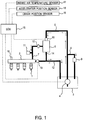
- Fig. 1 is a diagram showing the basic configuration of a fuel injection control system for an internal combustion engine.
- the fuel injection control system has fuel injection valves 1 for injecting fuel into cylinders of the internal combustion engine.
- the fuel injection valves 1 are connected to a delivery pipe 2. Although four fuel injection valves 1 are connected to the delivery pipe in the case illustrated in Fig. 1 , the number of fuel injection valves 1 may be five or more or three or less.
- the fuel injection control system has a low pressure fuel pump 4 that pumps up fuel stored in a fuel tank 3.
- the low pressure fuel pump 4 is a rotary pump that is driven by an electric motor. Low pressure fuel discharged from the low pressure fuel pump 4 is delivered to an inlet port of a high pressure fuel pump 6 through a low pressure fuel passage 5.
- the high pressure fuel pump 6 is a reciprocating pump (plunger pump) that is driven by the power of the internal combustion engine (e.g. by means of rotational force of a cam shaft).
- An inlet valve 60 for switching between opening and closing of the inlet port is provided at the inlet port of the high pressure fuel pump 6.
- the inlet valve 60 is an electromagnetic valve mechanism that changes the discharge rate of the high pressure fuel pump 6 by changing the opening/closing timing relative to the position of the plunger.
- To the discharge port of the high pressure pump 6 is connected the base end of a high pressure fuel passage 7.
- the terminal end of the high pressure fuel passage 7 is connected to the aforementioned delivery pipe 2.
- a pressure regulator 9 is provided in the middle of the branch passage 8. The pressure regulator 9 is adapted to open when the pressure (fuel pressure) in the low pressure fuel passage 5 exceeds a predetermined value, thereby returning surplus fuel in the low pressure fuel passage 5 to the fuel tank 3 through the branch passage 8.
- a check valve 10 and a pulsation damper 11 are provided in the middle of the high pressure passage 7.
- the check valve 10 is a one way valve that allows the flow from the discharge port of the aforementioned high pressure fuel pump 6 toward the aforementioned delivery pipe 2 and restricts the flow from the aforementioned delivery pipe 2 toward the discharge port of the aforementioned high pressure fuel pump 6.
- the pulsation damper 11 is used to damp the pulsation of fuel caused with the operation (i.e. sucking and discharging) of the aforementioned high pressure fuel pump 6.
- a relief valve 13 for switching between opening and closing of the return passage 12 is provided in the middle of the return passage 12.
- the relief valve 13 is an electric or electromagnetic valve mechanism that is opened when the fuel pressure in the delivery pipe 2 exceeds a target value.
- the base end of the communication passage 14 is connected to the aforementioned high pressure fuel pump 6.
- the communication passage 14 lets surplus fuel discharged from the aforementioned high pressure fuel pump 6 flow into the return passage 12.
- the fuel injection control system has an electronic control unit (ECU) 15 that controls the above-described components.
- the ECU 15 is electrically connected with various sensors such as a fuel pressure sensor 16, an intake air temperature sensor 17, an accelerator position sensor 18, and a crank position sensor 19.
- the fuel pressure sensor 16 is a sensor that outputs an electrical signal correlating with the fuel pressure in the delivery pipe 2.
- the fuel pressure sensor 16 may be provided in the high pressure fuel passage 7.
- the intake air temperature sensor 17 outputs an electrical signal correlating with the temperature of air taken into the internal combustion engine.
- the accelerator position sensor 18 outputs an electrical signal correlating with the amount of operation of the accelerator pedal (or the accelerator opening degree).
- the crank position sensor 19 is a sensor that outputs an electrical signal correlating with the rotational position of the output shaft (or crankshaft) of the internal combustion engine.
- the ECU 15 controls the low pressure fuel pump 4 and the inlet valve 60 based on signals output from the above-described various sensors. For instance, the ECU 15 adjusts the opening/closing timing of the inlet valve 60 in such a way that the output signal of the fuel pressure sensor 16 (i.e. the actual fuel pressure) converges to a target value. In doing so, the ECU 15 performs a proportional-integral control (PI control) of the duty cycle (i.e. the ratio of the energized period and the non-energized period in a solenoid) as a control quantity of the inlet valve 60 based on the difference between the actual fuel pressure and a target value. The aforementioned target value is determined as a function of the desired fuel injection quantity through the fuel injection valve 1.
- PI control proportional-integral control
- the ECU 15 calculates the duty cycle by adding a control value (or feed forward term) determined in relation to the desired fuel injection quantity, a control value (or proportional term) determined in relation to the difference between the actual fuel pressure and the target value (which will be hereinafter referred to as the "fuel pressure difference") and a control value (or integral term) obtained by integrating a part of the difference between the actual fuel pressure and the target value.
- This calculation of the duty cycle by the ECU 15 embodies the control section according to the present invention.
- the relationship between the aforementioned fuel pressure difference and the feed forward term and the relationship between the aforementioned fuel pressure difference and the proportional term shall be determined in advance by an adaptation process based on an experiment etc.
- the proportion of a portion of the aforementioned fuel pressure difference to be added to the integral term shall also be determined in advance by an adaptation process based on an experiment etc.
- the ECU 15 executes a lowering process in which the ECU 15 lowers the discharge pressure of the low pressure fuel pump 4 (or feed pressure) in order to reduce the power consumption in the low pressure fuel pump 4 as much as possible. Specifically, the ECU 15 lowers the discharge pressure of the low pressure fuel pump 4 by a constant step (which will be hereinafter referred to as the "lowering coefficient"). If the discharge pressure of the low pressure fuel pump 4 falls steeply, there is a possibility that the pressure of the fuel in the low pressure fuel passage 5 will become much lower than the saturation vapor pressure of the fuel. If this occurs, a large amount of vapor will be generated in the low pressure fuel passage 5, and a suction failure or discharge failure will be caused in the high pressure fuel pump 6.
- the aforementioned lowering coefficient be set to be as high as possible so long as the fuel pressure in the low pressure fuel passage 5 is not made much lower than the saturation vapor pressure. It is desirable that the lowering coefficient be obtained in advance by an adaptation process such as an experiment.
- One method of achieving this may be providing a sensor for measuring the fuel pressure in the low pressure fuel passage 5 and a sensor for determining the saturation vapor pressure of the fuel and raising the discharge pressure of the low pressure fuel pump 4 when the fuel pressure in the low pressure fuel passage 5 becomes lower than the saturation vapor pressure.
- this method will encounter a problem that a deterioration in the vehicle mountability and an increase in the manufacturing cost will result due to an increase in the number of parts in the fuel injection control system.
- the discharge pressure of the low pressure fuel pump 4 is adjusted based on the tendency of change in the integral term used in calculating the duty cycle of the high pressure fuel pump 6.
- Fig. 2 shows the behavior of the integral term It and the fuel pressure Ph in the high pressure fuel passage 7 with continuous decrease in the discharge pressure Pl of the low pressure fuel pump 4 (or feed pressure).
- the integral term It exhibits a moderate increasing tendency.
- a suction failure or a discharge failure occurs in the high pressure fuel pump 6 (at t2 in Fig. 2 ).
- the increasing rate of the integral term It becomes higher and the fuel pressure Ph in the high pressure fuel passage 7 decreases.
- a consideration of the relationship shown in Fig. 2 may suggest increasing the discharge pressure of the low pressure fuel pump 4 when the magnitude (or absolute value) of the integral term It exceeds a threshold value.
- the value of the integral term It increases not only with the generation of vapor but also with a rise in the fuel temperature and/or an increase in the desired injection quantity.
- the discharge pressure of the low pressure fuel pump 4 be adjusted based on the tendency of change in the integral term It per certain time period (for example, per execution cycle of the lowering process or per cycle of calculation of the duty cycle of the high pressure fuel pump 6).
- a preferable method is, for example, lowering the discharge pressure of the low pressure fuel pump 4 when the integral term It is constant or in a decreasing tendency and raising the discharge pressure of the low pressure fuel pump 4 when the integral term It is in an increasing tendency. This method enables detecting the generation of vapor before a suction failure or a discharge failure occurs in the high pressure fuel pump 6 (for example in the period from t1 to t2 in Fig. 2 ).
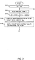
- Fig. 3 is a flow chart of a lowering process routine.
- the lowering process routine is stored in advance in a ROM of the ECU 15 and the execution of this routine is triggered by the start-up of the internal combustion engine (e.g. when the ignition switch is turned from off to on).
- the ECU 15 firstly executes the process of step S101. Specifically, the ECU 15 sets the drive current Id for the low pressure fuel pump 4 to an initial value Id0.
- step S103 the ECU 15 calculates the drive current Id for the low pressure fuel pump 4 using the difference ⁇ It calculated in the above step S102 and a lowering coefficient Cdwn.
- ⁇ is a moderating coefficient, which is determined in advance by an adaptation process based on an experiment etc.
- step S104 the ECU 15 executes a guard process with respect to the drive current Id obtained in the above step S103. Specifically, the ECU 15 determines whether or not the drive current Id obtained in the above step S103 is larger than a lower limit value and smaller than an upper limit value. If the drive current Id obtained in the above step S103 is larger than the lower limit value and smaller than the upper limit value, the ECU 15 sets the target drive current Idtrg to the aforementioned drive current Id. If the aforementioned drive current Id is larger than the upper limit value, the ECU 15 sets the target drive current Idtrg to a value equal to the upper limit value. If the aforementioned drive current Id is smaller than the lower limit value, the ECU 15 sets the target drive current Idtrg to a value equal to the lower limit value.
- step S105 the ECU 15 supplies the target drive current Idtrg set in the above step S104 to the low pressure fuel pump 4 to thereby drive the low pressure pump 4.
- the ECU 15 executes the process of step S102 and the subsequent steps repeatedly after executing the process of step S105.
- the discharge pressure of the lower pressure fuel pump 4 is lowered when the integral term It is constant or exhibits a decreasing tendency (namely, when the value of the difference ⁇ It is zero or negative) and raised when the integral term It exhibits an increasing tendency (namely, when the value of the difference ⁇ It is positive).
- the lowering of the feed pressure Pl can be stopped before a large amount of vapor is generated in the low pressure fuel passage 5 (i.e. at the time when vapor starts to be generated).
- the feed pressure Pl can be lowered as much as possible without leading to a large decrease in the fuel pressure Ph or a deviation of the air-fuel ratio, as shown in Fig. 4 .
- the lowering of the feed pressure Pl is stopped, the larger the aforementioned difference ⁇ It is, the higher the feed pressure Pl will be. Therefore, it is possible to prevent a suction failure and discharge failure in the high pressure fuel pump 6 from occurring more reliably.
- the lowering process in this embodiment does not need a sensor for measuring the fuel pressure in the low pressure fuel passage 5 or a sensor for determining the saturation vapor pressure of the fuel. Therefore, it does not invite a deterioration in the vehicle mountability of the fuel injection control system or an increase in the manufacturing cost of the system.
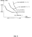
- Fig. 5 is a graph showing the relationship between the feed pressure Pl and the magnitude (or absolute value) of the integral term It.
- the solid curve in Fig. 5 represents the relationship in a case where the fuel temperature is T1.
- the alternate long and short dashed curve in Fig. 5 represents the relationship in a case where the fuel temperature is T2 that is higher than the aforementioned temperature T1.
- the chain double-dashed curve in Fig. 5 represents the relationship in a case where the fuel temperature is T3 that is higher than the aforementioned temperature T2.
- the magnitude (or absolute value) of the integral term It is larger when the fuel temperature is high than when the fuel temperature is low.
- the degree of increase in the integral term It in the case where the feed pressure Pl is lower than the saturation vapor pressure is larger when the fuel temperature is high than when the fuel temperature is low.
- the difference between the feed pressure Pl at the time when vapor starts to be generated in the low pressure fuel passage 5 and the feed pressure Pl at the time when a suction failure or discharge failure in the high pressure fuel pump 6 occurs (or when a decrease in the fuel pressure Ph in the high pressure fuel passage 7 occurs) is small.
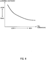
- the value of the lowering coefficient Cdwn is set smaller when the fuel temperature is high than when the fuel temperature is low as shown in Fig. 6 .
- the rate of decrease in the feed pressure Pl in a certain period becomes lower when the fuel temperature is high than when the fuel temperature is low.
- the feed pressure Pl can be lowered rapidly when the fuel temperature is low, while when the fuel temperature is high the feed pressure Pl can be lowered without a rapid increase in the amount of vapor generated in the low pressure fuel passage 5.
- a parameter used as an argument in setting the lowering coefficient Cdwn may be an actually measured value of the fuel temperature, though this requires the low pressure fuel passage 5 to be equipped with a temperature sensor. Alternately, use may be made of the temperature of cooling water circulating in the internal combustion engine, the temperature of lubricant oil in the internal combustion engine, or the signal output from the intake air temperature sensor 17 (i.e. the intake air temperature).
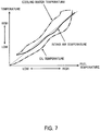
- Fig. 7 is a graph showing the relationships of the cooling water temperature, the oil temperature and the intake air temperature in relation to the fuel temperature.
- the solid curve in Fig. 7 represents the intake air temperature.
- the alternate long and short dashed curve in Fig. 7 represents the temperature of lubricant oil (oil temperature).
- the chain double-dashed curve in Fig. 7 represents the temperature of cooling water (cooling water temperature).
- the intake air temperature, the oil temperature and the cooling water temperature change substantially in conformity with the fuel temperature.
- the intake air temperature has a higher correlation with the fuel temperature as compared to the oil temperature and the cooling water temperature. It is considered that this is because the intake air temperature is the temperature measured by the intake air temperature sensor 17 provided in the engine room. More specifically, it is considered that the temperature in the low pressure fuel passage 5 is substantially equal to the temperature in the engine room and that the temperature of air measured by the intake air temperature sensor 17 also is substantially equal to the temperature in the engine room.
- the signal output from the intake air temperature sensor 17 i.e. the intake air temperature
- the intake air temperature is used as a parameter that correlates with the fuel temperature.
- the above-described relationship between the various temperatures and the fuel temperature might differ depending on the specifications of the internal combustion engine and/or the vehicle. Therefore, a parameter other than the intake air temperature may be used in such cases.
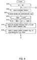
- Fig. 8 is a flow chart of a lowering process routine in this embodiment.
- the processes same as those in the lowering process routine in the above-described first embodiment are denoted by the same symbols.
- step S201 the ECU 15 reads the signal (intake air temperature) Tint output from the intake air temperature sensor 17.
- the ECU 15 may use a map in which the relationship described with reference to Fig. 6 is specified.
- step S103 the ECU 15 calculates the drive current Id for the low pressure fuel pump 4 using the integral term It read in step S102 and the lowering coefficient Cdwn obtained in step S202.
- the feed pressure Pl can be lowered as rapidly as possible without inviting a significant decrease in the fuel pressure Ph or a deviation of the air-fuel ratio.
- the intake air temperature, the cooling water temperature and the oil temperature have been mentioned as parameters that correlate with the fuel temperature, the parameters are not limited to them.
- the magnitude (or absolute value) of the integral term It may be used as a parameter to calculate the lowering coefficient Cdwn.
- the degree of increase in the integral term It or the likelihood of the generation of vapor in the low pressure fuel passage 5 tends to be high when the load (or accelerator opening degree) and/or the speed of the internal combustion engine is high. Therefore, the load and/or the speed of the internal combustion engine may be used as an argument to calculate the lowering coefficient Cdwn, or the engine load and/or the engine speed and the fuel temperature may be used as arguments to calculate the lowering coefficient Cdwn.
Landscapes
- Engineering & Computer Science (AREA)
- Chemical & Material Sciences (AREA)
- Combustion & Propulsion (AREA)
- Mechanical Engineering (AREA)
- General Engineering & Computer Science (AREA)
- Electrical Control Of Air Or Fuel Supplied To Internal-Combustion Engine (AREA)
- Fuel-Injection Apparatus (AREA)
Claims (9)
- Système de commande de l'injection de carburant pour un moteur à combustion interne dans lequel du carburant refoulé d'une pompe à carburant à basse pression (4) est fourni à un injecteur de carburant (1) avec sa pression augmentée par une pompe à carburant à haute pression (6), dans lequel ladite pompe à basse pression (4) est commandée par une unité de commande électronique (15), comprenant :une soupape d'admission (60) pour faire varier le rapport de refoulement de la pompe à carburant à haute pression (6) ;une section de traitement qui exécute un processus d'abaissement consistant à abaisser une pression d'alimentation qui est la pression de refoulement de ladite pompe à carburant à basse pression (6) ;un capteur de pression (16) qui mesure la pression de refoulement de ladite pompe à carburant à haute pression (6) ;une section de commande qui réalise une commande proportionnelle-intégrale du cycle de travail de ladite soupape d'admission (60) sur la base de la différence entre une pression de refoulement cible de ladite pompe à carburant à haute pression (4) et une valeur de mesure dudit capteur de pression (16) ;le système de commande de l'injection de carburant étant caractérisé en ce qu'il comprend en outre :
une section d'interruption qui interrompt ledit processus d'abaissement en référence à une tendance de variation dans un terme d'intégrale utilisé dans la commande proportionnelle-intégrale au cours de l'exécution dudit processus d'abaissement. - Système de commande de l'injection de carburant pour un moteur à combustion interne selon la revendication 1, dans lequel ladite section d'interruption interrompt ledit processus d'abaissement lorsque ledit terme d'intégrale présente une tendance croissante.
- Système de commande de l'injection de carburant pour un moteur à combustion interne selon la revendication 1 ou 2, dans lequel lorsque ledit processus d'abaissement est interrompu par ladite section d'interruption, ladite section de traitement maintient ladite pression d'alimentation inchangée ou augmente ladite pression d'alimentation.
- Système de commande de l'injection de carburant pour un moteur à combustion interne selon la revendication 3, dans lequel ladite section de traitement amène ladite pression d'alimentation à être plus élevée lorsque la quantité de variation dans ledit terme d'intégrale est élevée que lorsqu'elle est faible.
- Système de commande de l'injection de carburant pour un moteur à combustion interne selon l'une quelconque des revendications 1 à 4, dans lequel le taux d'abaissement de la pression d'alimentation dans ledit processus d'abaissement est fait varier en relation avec un état de fonctionnement du moteur à combustion interne.
- Système de commande de l'injection de carburant pour un moteur à combustion interne selon la revendication 5, dans lequel le taux d'abaissement de la pression d'alimentation dans ledit processus d'abaissement est amené à être plus faible lorsqu'un paramètre de température qui est corrélé à la température de carburant est élevé que lorsqu'il est faible.
- Système de commande de l'injection de carburant pour un moteur à combustion interne selon la revendication 6, dans lequel ledit paramètre de température est au moins l'un de la température d'eau de refroidissement, de la température d'huile de lubrification et de la température d'air d'admission.
- Système de commande de l'injection de carburant pour un moteur à combustion interne selon la revendication 5, dans lequel le taux d'abaissement de la pression d'alimentation dans ledit processus d'abaissement est amené à être plus faible lorsque la charge de moteur est élevée que lorsqu'elle est faible.
- Système de commande de l'injection de carburant pour un moteur à combustion interne selon l'une quelconque des revendications 1 à 4, dans lequel le taux d'abaissement de la pression d'alimentation dans ledit processus d'abaissement est amené à être plus faible lorsque la valeur absolue dudit terme d'intégrale est élevée que lorsqu'elle est faible.
Applications Claiming Priority (1)
| Application Number | Priority Date | Filing Date | Title |
|---|---|---|---|
| PCT/JP2010/069101 WO2012056534A1 (fr) | 2010-10-27 | 2010-10-27 | Système de commande d'injection de carburant de moteur à combustion interne |
Publications (3)
| Publication Number | Publication Date |
|---|---|
| EP2634411A1 EP2634411A1 (fr) | 2013-09-04 |
| EP2634411A4 EP2634411A4 (fr) | 2016-08-10 |
| EP2634411B1 true EP2634411B1 (fr) | 2019-12-04 |
Family
ID=45993289
Family Applications (1)
| Application Number | Title | Priority Date | Filing Date |
|---|---|---|---|
| EP10858923.5A Active EP2634411B1 (fr) | 2010-10-27 | 2010-10-27 | Système de commande de l'injection de carburant pour un moteur à combustion interne |
Country Status (6)
| Country | Link |
|---|---|
| US (1) | US9074550B2 (fr) |
| EP (1) | EP2634411B1 (fr) |
| JP (1) | JP5494818B2 (fr) |
| CN (1) | CN103080528B (fr) |
| BR (1) | BR112012033464A2 (fr) |
| WO (1) | WO2012056534A1 (fr) |
Families Citing this family (10)
| Publication number | Priority date | Publication date | Assignee | Title |
|---|---|---|---|---|
| JP5733396B2 (ja) | 2011-07-01 | 2015-06-10 | トヨタ自動車株式会社 | 内燃機関の燃料噴射制御システム |
| EP2762718A4 (fr) * | 2011-09-28 | 2015-12-16 | Toyota Motor Co Ltd | Système de régulation d'injection de carburant pour moteur à combustion interne |
| CN102434302B (zh) * | 2011-12-31 | 2016-01-06 | 中国第一汽车股份有限公司 | 缸内直喷汽油机高压起动控制方法 |
| JP5875970B2 (ja) * | 2012-12-21 | 2016-03-02 | 愛三工業株式会社 | 自動車の燃料供給装置 |
| GB201316439D0 (en) * | 2013-09-16 | 2013-10-30 | Delphi Tech Holding Sarl | Hybrid fuel injection equipment |
| JP6197828B2 (ja) * | 2015-05-27 | 2017-09-20 | トヨタ自動車株式会社 | 車両の制御装置 |
| US10738749B1 (en) * | 2019-01-18 | 2020-08-11 | Pratt & Whitney Canada Corp. | Method of using heat from fuel of common-rail injectors |
| US10865728B2 (en) | 2019-01-18 | 2020-12-15 | Pratt & Whitney Canada Corp. | Method of using backflow from common-rail fuel injector |
| JP6852754B2 (ja) * | 2019-06-17 | 2021-03-31 | トヨタ自動車株式会社 | 燃料噴射制御装置 |
| CN115628146B (zh) * | 2022-09-30 | 2024-08-20 | 东风汽车集团股份有限公司 | 直喷发动机油压控制方法、装置、设备及存储介质 |
Family Cites Families (14)
| Publication number | Priority date | Publication date | Assignee | Title |
|---|---|---|---|---|
| DE10001882A1 (de) * | 2000-01-19 | 2001-08-02 | Bosch Gmbh Robert | Verfahren zum Betrieb einer Vorförderpumpe eines Kraftstoffzumesssystems und Kraftstoffzumesssystem einer direkteinspritzenden Brennkraftmaschine |
| JP2005076568A (ja) | 2003-09-02 | 2005-03-24 | Nissan Motor Co Ltd | 内燃機関の燃料供給装置 |
| JP2005307931A (ja) * | 2004-04-26 | 2005-11-04 | Hitachi Ltd | 内燃機関の燃料供給装置 |
| DE102004045738B4 (de) * | 2004-09-21 | 2013-05-29 | Continental Automotive Gmbh | Verfahren und Vorrichtung zum Steuern einer Brennkraftmaschine |
| CN101451474A (zh) * | 2004-10-07 | 2009-06-10 | 丰田自动车株式会社 | 用于内燃机的燃料供应设备 |
| JP2006258032A (ja) * | 2005-03-18 | 2006-09-28 | Toyota Motor Corp | 車両の制御装置 |
| JP4534866B2 (ja) | 2005-05-19 | 2010-09-01 | トヨタ自動車株式会社 | エンジンの制御装置 |
| EP1757793A1 (fr) * | 2005-08-22 | 2007-02-28 | Inergy Automotive Systems Research (SA) | Système de contrôle d'une pompe à combustible |
| JP4242380B2 (ja) | 2005-11-01 | 2009-03-25 | 本田技研工業株式会社 | 燃料ポンプの制御装置 |
| JP4874816B2 (ja) * | 2007-01-16 | 2012-02-15 | 日立オートモティブシステムズ株式会社 | 内燃機関の燃料供給装置 |
| JP4661930B2 (ja) | 2008-09-19 | 2011-03-30 | トヨタ自動車株式会社 | 内燃機関の燃料供給装置 |
| JP5126102B2 (ja) * | 2009-02-10 | 2013-01-23 | トヨタ自動車株式会社 | 内燃機関の燃料供給装置 |
| IT1395038B1 (it) * | 2009-08-12 | 2012-09-05 | Magneti Marelli Spa | Metodo di controllo di un impianto di iniezione diretta di tipo common-rail |
| US8820299B2 (en) * | 2011-04-27 | 2014-09-02 | Toyota Jidosha Kabushiki Kaisha | Fuel injection control system for internal combustion engine |
-
2010
- 2010-10-27 JP JP2012540574A patent/JP5494818B2/ja not_active Expired - Fee Related
- 2010-10-27 BR BR112012033464A patent/BR112012033464A2/pt not_active Application Discontinuation
- 2010-10-27 WO PCT/JP2010/069101 patent/WO2012056534A1/fr not_active Ceased
- 2010-10-27 CN CN201080068600.1A patent/CN103080528B/zh not_active Expired - Fee Related
- 2010-10-27 US US13/814,759 patent/US9074550B2/en not_active Expired - Fee Related
- 2010-10-27 EP EP10858923.5A patent/EP2634411B1/fr active Active
Non-Patent Citations (1)
| Title |
|---|
| None * |
Also Published As
| Publication number | Publication date |
|---|---|
| US9074550B2 (en) | 2015-07-07 |
| BR112012033464A2 (pt) | 2016-11-22 |
| CN103080528B (zh) | 2015-01-14 |
| US20130138327A1 (en) | 2013-05-30 |
| EP2634411A1 (fr) | 2013-09-04 |
| JPWO2012056534A1 (ja) | 2014-03-20 |
| WO2012056534A1 (fr) | 2012-05-03 |
| CN103080528A (zh) | 2013-05-01 |
| JP5494818B2 (ja) | 2014-05-21 |
| EP2634411A4 (fr) | 2016-08-10 |
Similar Documents
| Publication | Publication Date | Title |
|---|---|---|
| EP2634411B1 (fr) | Système de commande de l'injection de carburant pour un moteur à combustion interne | |
| EP2713039B1 (fr) | Système de commande d'injection de carburant pour moteur à combustion interne | |
| US9194353B2 (en) | Fuel injection control system for internal combustion engine | |
| US10113500B2 (en) | Fuel-pressure controller for direct injection engine | |
| US7143747B2 (en) | Common rail fuel injection system | |
| US10011269B2 (en) | Identifying in-range fuel pressure sensor error | |
| RU2706853C2 (ru) | Способ (варианты) и система управления топливной системой | |
| US20100268441A1 (en) | Controller for fuel pump | |
| US10189466B2 (en) | Identifying in-range fuel pressure sensor error | |
| JP2009115009A (ja) | 筒内噴射エンジンの停止後燃圧制御装置 | |
| EP2762718A1 (fr) | Système de régulation d'injection de carburant pour moteur à combustion interne | |
| JP2011185158A (ja) | 内燃機関の高圧燃料供給システムの異常診断装置 | |
| JP6146274B2 (ja) | 内燃機関の制御装置 | |
| JP2007255394A (ja) | ポンプ故障診断装置 | |
| JP5733396B2 (ja) | 内燃機関の燃料噴射制御システム | |
| JP2010116835A (ja) | 筒内噴射式内燃機関の高圧ポンプ制御装置 | |
| JP2010216370A (ja) | 燃料供給制御装置 | |
| JP2008274842A (ja) | 減圧弁制御装置およびそれを用いた燃料噴射システム | |
| JP4144360B2 (ja) | 蓄圧式燃料噴射装置 | |
| JP2009221906A (ja) | 筒内噴射式内燃機関の低圧ポンプ制御装置 | |
| JP5708396B2 (ja) | 内燃機関の燃料噴射制御システム | |
| JP2005344573A (ja) | 内燃機関用燃料噴射装置 | |
| JP5716684B2 (ja) | 内燃機関の燃料噴射制御システム | |
| JP2001295725A (ja) | 内燃機関の燃料圧力制御装置 | |
| JP5884710B2 (ja) | 燃料圧力制御装置 |
Legal Events
| Date | Code | Title | Description |
|---|---|---|---|
| PUAI | Public reference made under article 153(3) epc to a published international application that has entered the european phase |
Free format text: ORIGINAL CODE: 0009012 |
|
| 17P | Request for examination filed |
Effective date: 20130213 |
|
| AK | Designated contracting states |
Kind code of ref document: A1 Designated state(s): AL AT BE BG CH CY CZ DE DK EE ES FI FR GB GR HR HU IE IS IT LI LT LU LV MC MK MT NL NO PL PT RO RS SE SI SK SM TR |
|
| DAX | Request for extension of the european patent (deleted) | ||
| RA4 | Supplementary search report drawn up and despatched (corrected) |
Effective date: 20160711 |
|
| RIC1 | Information provided on ipc code assigned before grant |
Ipc: F02M 59/36 20060101ALN20160705BHEP Ipc: F02M 37/00 20060101AFI20160705BHEP Ipc: F02D 41/30 20060101ALI20160705BHEP Ipc: F02D 41/14 20060101ALN20160705BHEP Ipc: F02D 41/38 20060101ALI20160705BHEP |
|
| REG | Reference to a national code |
Ref country code: DE Ref legal event code: R079 Ref document number: 602010062292 Country of ref document: DE Free format text: PREVIOUS MAIN CLASS: F02M0037080000 Ipc: F02M0037000000 |
|
| GRAP | Despatch of communication of intention to grant a patent |
Free format text: ORIGINAL CODE: EPIDOSNIGR1 |
|
| STAA | Information on the status of an ep patent application or granted ep patent |
Free format text: STATUS: GRANT OF PATENT IS INTENDED |
|
| RIC1 | Information provided on ipc code assigned before grant |
Ipc: F02M 37/00 20060101AFI20190521BHEP Ipc: F02D 41/38 20060101ALI20190521BHEP Ipc: F02M 59/36 20060101ALN20190521BHEP Ipc: F02D 41/14 20060101ALN20190521BHEP Ipc: F02D 41/30 20060101ALI20190521BHEP |
|
| INTG | Intention to grant announced |
Effective date: 20190617 |
|
| GRAS | Grant fee paid |
Free format text: ORIGINAL CODE: EPIDOSNIGR3 |
|
| GRAA | (expected) grant |
Free format text: ORIGINAL CODE: 0009210 |
|
| STAA | Information on the status of an ep patent application or granted ep patent |
Free format text: STATUS: THE PATENT HAS BEEN GRANTED |
|
| AK | Designated contracting states |
Kind code of ref document: B1 Designated state(s): AL AT BE BG CH CY CZ DE DK EE ES FI FR GB GR HR HU IE IS IT LI LT LU LV MC MK MT NL NO PL PT RO RS SE SI SK SM TR |
|
| REG | Reference to a national code |
Ref country code: GB Ref legal event code: FG4D |
|
| REG | Reference to a national code |
Ref country code: CH Ref legal event code: EP |
|
| REG | Reference to a national code |
Ref country code: AT Ref legal event code: REF Ref document number: 1209718 Country of ref document: AT Kind code of ref document: T Effective date: 20191215 |
|
| REG | Reference to a national code |
Ref country code: DE Ref legal event code: R096 Ref document number: 602010062292 Country of ref document: DE |
|
| REG | Reference to a national code |
Ref country code: IE Ref legal event code: FG4D |
|
| REG | Reference to a national code |
Ref country code: NL Ref legal event code: MP Effective date: 20191204 |
|
| REG | Reference to a national code |
Ref country code: LT Ref legal event code: MG4D |
|
| PG25 | Lapsed in a contracting state [announced via postgrant information from national office to epo] |
Ref country code: LT Free format text: LAPSE BECAUSE OF FAILURE TO SUBMIT A TRANSLATION OF THE DESCRIPTION OR TO PAY THE FEE WITHIN THE PRESCRIBED TIME-LIMIT Effective date: 20191204 Ref country code: ES Free format text: LAPSE BECAUSE OF FAILURE TO SUBMIT A TRANSLATION OF THE DESCRIPTION OR TO PAY THE FEE WITHIN THE PRESCRIBED TIME-LIMIT Effective date: 20191204 Ref country code: GR Free format text: LAPSE BECAUSE OF FAILURE TO SUBMIT A TRANSLATION OF THE DESCRIPTION OR TO PAY THE FEE WITHIN THE PRESCRIBED TIME-LIMIT Effective date: 20200305 Ref country code: NO Free format text: LAPSE BECAUSE OF FAILURE TO SUBMIT A TRANSLATION OF THE DESCRIPTION OR TO PAY THE FEE WITHIN THE PRESCRIBED TIME-LIMIT Effective date: 20200304 Ref country code: SE Free format text: LAPSE BECAUSE OF FAILURE TO SUBMIT A TRANSLATION OF THE DESCRIPTION OR TO PAY THE FEE WITHIN THE PRESCRIBED TIME-LIMIT Effective date: 20191204 Ref country code: LV Free format text: LAPSE BECAUSE OF FAILURE TO SUBMIT A TRANSLATION OF THE DESCRIPTION OR TO PAY THE FEE WITHIN THE PRESCRIBED TIME-LIMIT Effective date: 20191204 Ref country code: FI Free format text: LAPSE BECAUSE OF FAILURE TO SUBMIT A TRANSLATION OF THE DESCRIPTION OR TO PAY THE FEE WITHIN THE PRESCRIBED TIME-LIMIT Effective date: 20191204 Ref country code: BG Free format text: LAPSE BECAUSE OF FAILURE TO SUBMIT A TRANSLATION OF THE DESCRIPTION OR TO PAY THE FEE WITHIN THE PRESCRIBED TIME-LIMIT Effective date: 20200304 |
|
| PG25 | Lapsed in a contracting state [announced via postgrant information from national office to epo] |
Ref country code: RS Free format text: LAPSE BECAUSE OF FAILURE TO SUBMIT A TRANSLATION OF THE DESCRIPTION OR TO PAY THE FEE WITHIN THE PRESCRIBED TIME-LIMIT Effective date: 20191204 Ref country code: HR Free format text: LAPSE BECAUSE OF FAILURE TO SUBMIT A TRANSLATION OF THE DESCRIPTION OR TO PAY THE FEE WITHIN THE PRESCRIBED TIME-LIMIT Effective date: 20191204 |
|
| PG25 | Lapsed in a contracting state [announced via postgrant information from national office to epo] |
Ref country code: AL Free format text: LAPSE BECAUSE OF FAILURE TO SUBMIT A TRANSLATION OF THE DESCRIPTION OR TO PAY THE FEE WITHIN THE PRESCRIBED TIME-LIMIT Effective date: 20191204 |
|
| PG25 | Lapsed in a contracting state [announced via postgrant information from national office to epo] |
Ref country code: PT Free format text: LAPSE BECAUSE OF FAILURE TO SUBMIT A TRANSLATION OF THE DESCRIPTION OR TO PAY THE FEE WITHIN THE PRESCRIBED TIME-LIMIT Effective date: 20200429 Ref country code: CZ Free format text: LAPSE BECAUSE OF FAILURE TO SUBMIT A TRANSLATION OF THE DESCRIPTION OR TO PAY THE FEE WITHIN THE PRESCRIBED TIME-LIMIT Effective date: 20191204 Ref country code: NL Free format text: LAPSE BECAUSE OF FAILURE TO SUBMIT A TRANSLATION OF THE DESCRIPTION OR TO PAY THE FEE WITHIN THE PRESCRIBED TIME-LIMIT Effective date: 20191204 Ref country code: EE Free format text: LAPSE BECAUSE OF FAILURE TO SUBMIT A TRANSLATION OF THE DESCRIPTION OR TO PAY THE FEE WITHIN THE PRESCRIBED TIME-LIMIT Effective date: 20191204 Ref country code: RO Free format text: LAPSE BECAUSE OF FAILURE TO SUBMIT A TRANSLATION OF THE DESCRIPTION OR TO PAY THE FEE WITHIN THE PRESCRIBED TIME-LIMIT Effective date: 20191204 |
|
| PG25 | Lapsed in a contracting state [announced via postgrant information from national office to epo] |
Ref country code: SM Free format text: LAPSE BECAUSE OF FAILURE TO SUBMIT A TRANSLATION OF THE DESCRIPTION OR TO PAY THE FEE WITHIN THE PRESCRIBED TIME-LIMIT Effective date: 20191204 Ref country code: IS Free format text: LAPSE BECAUSE OF FAILURE TO SUBMIT A TRANSLATION OF THE DESCRIPTION OR TO PAY THE FEE WITHIN THE PRESCRIBED TIME-LIMIT Effective date: 20200404 Ref country code: SK Free format text: LAPSE BECAUSE OF FAILURE TO SUBMIT A TRANSLATION OF THE DESCRIPTION OR TO PAY THE FEE WITHIN THE PRESCRIBED TIME-LIMIT Effective date: 20191204 |
|
| REG | Reference to a national code |
Ref country code: DE Ref legal event code: R097 Ref document number: 602010062292 Country of ref document: DE |
|
| REG | Reference to a national code |
Ref country code: AT Ref legal event code: MK05 Ref document number: 1209718 Country of ref document: AT Kind code of ref document: T Effective date: 20191204 |
|
| PLBE | No opposition filed within time limit |
Free format text: ORIGINAL CODE: 0009261 |
|
| STAA | Information on the status of an ep patent application or granted ep patent |
Free format text: STATUS: NO OPPOSITION FILED WITHIN TIME LIMIT |
|
| PG25 | Lapsed in a contracting state [announced via postgrant information from national office to epo] |
Ref country code: DK Free format text: LAPSE BECAUSE OF FAILURE TO SUBMIT A TRANSLATION OF THE DESCRIPTION OR TO PAY THE FEE WITHIN THE PRESCRIBED TIME-LIMIT Effective date: 20191204 |
|
| 26N | No opposition filed |
Effective date: 20200907 |
|
| PG25 | Lapsed in a contracting state [announced via postgrant information from national office to epo] |
Ref country code: SI Free format text: LAPSE BECAUSE OF FAILURE TO SUBMIT A TRANSLATION OF THE DESCRIPTION OR TO PAY THE FEE WITHIN THE PRESCRIBED TIME-LIMIT Effective date: 20191204 Ref country code: PL Free format text: LAPSE BECAUSE OF FAILURE TO SUBMIT A TRANSLATION OF THE DESCRIPTION OR TO PAY THE FEE WITHIN THE PRESCRIBED TIME-LIMIT Effective date: 20191204 Ref country code: AT Free format text: LAPSE BECAUSE OF FAILURE TO SUBMIT A TRANSLATION OF THE DESCRIPTION OR TO PAY THE FEE WITHIN THE PRESCRIBED TIME-LIMIT Effective date: 20191204 |
|
| PG25 | Lapsed in a contracting state [announced via postgrant information from national office to epo] |
Ref country code: IT Free format text: LAPSE BECAUSE OF FAILURE TO SUBMIT A TRANSLATION OF THE DESCRIPTION OR TO PAY THE FEE WITHIN THE PRESCRIBED TIME-LIMIT Effective date: 20191204 |
|
| REG | Reference to a national code |
Ref country code: CH Ref legal event code: PL |
|
| PG25 | Lapsed in a contracting state [announced via postgrant information from national office to epo] |
Ref country code: MC Free format text: LAPSE BECAUSE OF FAILURE TO SUBMIT A TRANSLATION OF THE DESCRIPTION OR TO PAY THE FEE WITHIN THE PRESCRIBED TIME-LIMIT Effective date: 20191204 Ref country code: LU Free format text: LAPSE BECAUSE OF NON-PAYMENT OF DUE FEES Effective date: 20201027 |
|
| REG | Reference to a national code |
Ref country code: BE Ref legal event code: MM Effective date: 20201031 |
|
| REG | Reference to a national code |
Ref country code: DE Ref legal event code: R084 Ref document number: 602010062292 Country of ref document: DE |
|
| PG25 | Lapsed in a contracting state [announced via postgrant information from national office to epo] |
Ref country code: BE Free format text: LAPSE BECAUSE OF NON-PAYMENT OF DUE FEES Effective date: 20201031 Ref country code: CH Free format text: LAPSE BECAUSE OF NON-PAYMENT OF DUE FEES Effective date: 20201031 Ref country code: LI Free format text: LAPSE BECAUSE OF NON-PAYMENT OF DUE FEES Effective date: 20201031 |
|
| REG | Reference to a national code |
Ref country code: GB Ref legal event code: 746 Effective date: 20210917 |
|
| PG25 | Lapsed in a contracting state [announced via postgrant information from national office to epo] |
Ref country code: IE Free format text: LAPSE BECAUSE OF NON-PAYMENT OF DUE FEES Effective date: 20201027 |
|
| PGFP | Annual fee paid to national office [announced via postgrant information from national office to epo] |
Ref country code: FR Payment date: 20210913 Year of fee payment: 12 |
|
| PGFP | Annual fee paid to national office [announced via postgrant information from national office to epo] |
Ref country code: GB Payment date: 20210915 Year of fee payment: 12 |
|
| PGFP | Annual fee paid to national office [announced via postgrant information from national office to epo] |
Ref country code: DE Payment date: 20210914 Year of fee payment: 12 |
|
| PG25 | Lapsed in a contracting state [announced via postgrant information from national office to epo] |
Ref country code: TR Free format text: LAPSE BECAUSE OF FAILURE TO SUBMIT A TRANSLATION OF THE DESCRIPTION OR TO PAY THE FEE WITHIN THE PRESCRIBED TIME-LIMIT Effective date: 20191204 Ref country code: MT Free format text: LAPSE BECAUSE OF FAILURE TO SUBMIT A TRANSLATION OF THE DESCRIPTION OR TO PAY THE FEE WITHIN THE PRESCRIBED TIME-LIMIT Effective date: 20191204 Ref country code: CY Free format text: LAPSE BECAUSE OF FAILURE TO SUBMIT A TRANSLATION OF THE DESCRIPTION OR TO PAY THE FEE WITHIN THE PRESCRIBED TIME-LIMIT Effective date: 20191204 |
|
| PG25 | Lapsed in a contracting state [announced via postgrant information from national office to epo] |
Ref country code: MK Free format text: LAPSE BECAUSE OF FAILURE TO SUBMIT A TRANSLATION OF THE DESCRIPTION OR TO PAY THE FEE WITHIN THE PRESCRIBED TIME-LIMIT Effective date: 20191204 |
|
| REG | Reference to a national code |
Ref country code: DE Ref legal event code: R119 Ref document number: 602010062292 Country of ref document: DE |
|
| GBPC | Gb: european patent ceased through non-payment of renewal fee |
Effective date: 20221027 |
|
| PG25 | Lapsed in a contracting state [announced via postgrant information from national office to epo] |
Ref country code: FR Free format text: LAPSE BECAUSE OF NON-PAYMENT OF DUE FEES Effective date: 20221031 Ref country code: DE Free format text: LAPSE BECAUSE OF NON-PAYMENT OF DUE FEES Effective date: 20230503 |
|
| PG25 | Lapsed in a contracting state [announced via postgrant information from national office to epo] |
Ref country code: GB Free format text: LAPSE BECAUSE OF NON-PAYMENT OF DUE FEES Effective date: 20221027 |