EP2634412B1 - Ventilateur d'injection - Google Patents
Ventilateur d'injection Download PDFInfo
- Publication number
- EP2634412B1 EP2634412B1 EP13152703.8A EP13152703A EP2634412B1 EP 2634412 B1 EP2634412 B1 EP 2634412B1 EP 13152703 A EP13152703 A EP 13152703A EP 2634412 B1 EP2634412 B1 EP 2634412B1
- Authority
- EP
- European Patent Office
- Prior art keywords
- valve
- valve needle
- housing
- stop surface
- stop
- Prior art date
- Legal status (The legal status is an assumption and is not a legal conclusion. Google has not performed a legal analysis and makes no representation as to the accuracy of the status listed.)
- Not-in-force
Links
- 238000002347 injection Methods 0.000 title claims description 51
- 239000007924 injection Substances 0.000 title claims description 51
- 239000000446 fuel Substances 0.000 claims description 13
- 238000002485 combustion reaction Methods 0.000 claims description 9
- 239000007921 spray Substances 0.000 claims description 3
- 238000010586 diagram Methods 0.000 description 4
- 239000000463 material Substances 0.000 description 3
- VYZAMTAEIAYCRO-UHFFFAOYSA-N Chromium Chemical compound [Cr] VYZAMTAEIAYCRO-UHFFFAOYSA-N 0.000 description 2
- 229910052804 chromium Inorganic materials 0.000 description 2
- 239000011651 chromium Substances 0.000 description 2
- 230000008092 positive effect Effects 0.000 description 2
- 230000015572 biosynthetic process Effects 0.000 description 1
- 230000006835 compression Effects 0.000 description 1
- 238000007906 compression Methods 0.000 description 1
- 230000001419 dependent effect Effects 0.000 description 1
- 238000011161 development Methods 0.000 description 1
- 230000018109 developmental process Effects 0.000 description 1
- 238000001595 flow curve Methods 0.000 description 1
- 230000004907 flux Effects 0.000 description 1
- 238000004519 manufacturing process Methods 0.000 description 1
- 239000000203 mixture Substances 0.000 description 1
- 239000000243 solution Substances 0.000 description 1
Images




Classifications
-
- F—MECHANICAL ENGINEERING; LIGHTING; HEATING; WEAPONS; BLASTING
- F02—COMBUSTION ENGINES; HOT-GAS OR COMBUSTION-PRODUCT ENGINE PLANTS
- F02M—SUPPLYING COMBUSTION ENGINES IN GENERAL WITH COMBUSTIBLE MIXTURES OR CONSTITUENTS THEREOF
- F02M51/00—Fuel-injection apparatus characterised by being operated electrically
- F02M51/06—Injectors peculiar thereto with means directly operating the valve needle
- F02M51/061—Injectors peculiar thereto with means directly operating the valve needle using electromagnetic operating means
- F02M51/0625—Injectors peculiar thereto with means directly operating the valve needle using electromagnetic operating means characterised by arrangement of mobile armatures
- F02M51/0664—Injectors peculiar thereto with means directly operating the valve needle using electromagnetic operating means characterised by arrangement of mobile armatures having a cylindrically or partly cylindrically shaped armature, e.g. entering the winding; having a plate-shaped or undulated armature entering the winding
- F02M51/0685—Injectors peculiar thereto with means directly operating the valve needle using electromagnetic operating means characterised by arrangement of mobile armatures having a cylindrically or partly cylindrically shaped armature, e.g. entering the winding; having a plate-shaped or undulated armature entering the winding the armature and the valve being allowed to move relatively to each other or not being attached to each other
-
- F—MECHANICAL ENGINEERING; LIGHTING; HEATING; WEAPONS; BLASTING
- F02—COMBUSTION ENGINES; HOT-GAS OR COMBUSTION-PRODUCT ENGINE PLANTS
- F02M—SUPPLYING COMBUSTION ENGINES IN GENERAL WITH COMBUSTIBLE MIXTURES OR CONSTITUENTS THEREOF
- F02M61/00—Fuel-injectors not provided for in groups F02M39/00 - F02M57/00 or F02M67/00
- F02M61/04—Fuel-injectors not provided for in groups F02M39/00 - F02M57/00 or F02M67/00 having valves, e.g. having a plurality of valves in series
- F02M61/042—The valves being provided with fuel passages
-
- F—MECHANICAL ENGINEERING; LIGHTING; HEATING; WEAPONS; BLASTING
- F02—COMBUSTION ENGINES; HOT-GAS OR COMBUSTION-PRODUCT ENGINE PLANTS
- F02M—SUPPLYING COMBUSTION ENGINES IN GENERAL WITH COMBUSTIBLE MIXTURES OR CONSTITUENTS THEREOF
- F02M61/00—Fuel-injectors not provided for in groups F02M39/00 - F02M57/00 or F02M67/00
- F02M61/16—Details not provided for in, or of interest apart from, the apparatus of groups F02M61/02 - F02M61/14
-
- F—MECHANICAL ENGINEERING; LIGHTING; HEATING; WEAPONS; BLASTING
- F02—COMBUSTION ENGINES; HOT-GAS OR COMBUSTION-PRODUCT ENGINE PLANTS
- F02M—SUPPLYING COMBUSTION ENGINES IN GENERAL WITH COMBUSTIBLE MIXTURES OR CONSTITUENTS THEREOF
- F02M61/00—Fuel-injectors not provided for in groups F02M39/00 - F02M57/00 or F02M67/00
- F02M61/16—Details not provided for in, or of interest apart from, the apparatus of groups F02M61/02 - F02M61/14
- F02M61/18—Injection nozzles, e.g. having valve seats; Details of valve member seated ends, not otherwise provided for
- F02M61/188—Spherical or partly spherical shaped valve member ends
Definitions
- the present invention relates to an injection valve, in particular for injecting fuel into an internal combustion engine.
- injection valves for example, for the channel or direct injection of gasoline, with a valve needle, which is moved by an actuator (solenoid or piezo actuator) against a closing spring so that a desired amount of fuel is selectively introduced.
- the magnet armature can be decoupled from the valve needle. Solutions are known which divide the moving mass of the valve needle into several sub-masses, which are coupled to one another by means of springs, guides and stop surfaces. Such a concept shows, for example, the DE 101 08 945 A1 , In general, the valve needle is pressed in the de-energized state by the return spring in the valve seat.
- FIG. 1 A diagram of an injection valve according to the prior art shows FIG. 1 , Here, the time t is recorded on the horizontal axis. On the vertical axis, an upper portion 20 shows a current curve 23.
- a middle portion 21 shows the course of a Ventilnadelhubes 24 with a solid line in a lower portion 22 and the central portion 21 is a dashed line a course of Magnetankerhubes 25 located.
- a detail 26 characterized.
- a stable state of the two-mass system is only reached when the valve needle, which is pressed by the closing spring in the direction of the armature, rests again on the armature. However, if the valve needle opening stream (see flow curve 23) is turned off so that the valve needle is in flight while the armature still remains at the inner pole, results in a valve closing from an undefined state.
- the detail 26 in FIG. 1 shows the ballistic flight curve of the valve needle after the armature has reached the inner pole. If, in addition, the valves differ from one member to the next in their needle movement, these differences in the so-called transitional range between partial and full-stroke operation can lead to considerable changes in the valve needle movement and thus in the delivered quantity as a target variable.
- An injection valve in particular for injecting fuel into an internal combustion engine, which includes, inter alia, a housing with at least one injection opening.
- the electromagnetically operable injection valve further comprises a stationary relative to the housing inner pole, which thus constitutes a housing-fixed component, a magnetically acting on the inner pole magnetic coil, a relative to the housing linearly movable armature, with respect to the housing and against the magnet armature linearly movable valve needle which together forms a valve seat with the housing.
- the first stop surface is formed by the entire lower end face of the inner pole.
- the valve needle strikes a large area with a radially projecting needle flange and its upper second stop surface, so that the risk of hydraulic sticking is increased here.
- the radially far projecting needle flange is in no case the linear guide of the valve needle.
- the injection valve according to the invention with the features of claim 1 makes it possible to limit the maximum possible valve needle stroke by a stop of the valve needle with the inner pole or with the housing.
- the ballistic curve of the valve needle according to detail 26 in FIG. 1 thus eliminates the Ventilnadelhubterrorism can be controlled so much more precise than before, and thus the amount of fuel to be delivered are specified in more detail.
- the time course of the valve needle stroke is defined more accurately than hitherto by mechanical stops and their arrangement.
- the invention thus improves the Mengenzutul of injectors. This has positive effects on the mixture formation in the combustion chamber with injectors and thus also positive effects on the combustion.
- due to the injection valve according to the invention emissions and consumption of an internal combustion engine are reduced and smoothness improved.
- an injection valve in particular for injecting fuel into an internal combustion engine, comprising a housing with at least one injection opening and a housing pole fixedly mounted relative to the housing. Furthermore, the injection valve comprises a magnetic coil acting magnetically on the inner pole and a magnet armature that is linearly movable relative to the housing. Furthermore, the injection valve comprises a relative to the housing and with respect to the magnet armature linearly movable valve needle, which together with the at least an injection port forms a valve seat. In the injection valve, a first, fixed relative to the housing stop surface and a second, formed on the valve needle stop surface is provided. In an end position of the valve needle strikes the second stop surface on the first stop surface.
- valve needle In this end position, the valve needle has the maximum valve needle lift, so that in this position the maximum amount of fuel can be passed through the spray opening.
- the maximum possible valve needle lift is limited via the first and second stop surfaces.
- the magnet armature preferably does not touch the inner pole in any position. It is a two-mass system according to the invention, since the valve needle and the magnet armature are arranged separately linearly movable relative to the housing.
- the first stop surface is formed on the inner pole.
- the inner pole comprises a stop bush, wherein the first stop surface is formed on this stop bushing.
- the stop bush is preferably designed to increase the life of a hard or curable or hardened or hard-coated material and thus leads to a cost-effective and durable stop. A previously used chromium layer on the inner pole can thus be omitted.
- a first return spring is preferably provided between the inner pole and the valve needle. This first return spring loads the valve needle in the direction of the valve seat, so that in the de-energized state of the magnetic coil, the valve seat is closed.
- a third stop face facing the valve seat is preferably formed on the valve needle, and a fourth stop face remote from the valve seat is formed on the magnet armature.
- the third abutment surface and the fourth abutment surface strike each other as the valve needle moves at.
- the magnet armature is moved via the magnetised inner pole.
- the fourth abutment surface strikes the third stop surface and thus the armature takes with the valve needle. This movement is stopped by the abutment of the first and second abutment surface between the valve needle and the inner pole or the housing.
- a second return spring for resetting the magnet armature is preferably provided.
- the second return spring preferably loads the armature in the direction of the valve seat.
- a spring cup is preferably attached to the armature. One end of the second return spring is supported against the spring cup and the other end of the second return spring rests against the valve needle, a valve needle-fixed component or against a housing-fixed component.
- a fifth, the valve seat facing stop surface and on the valve needle a sixth, the valve seat facing away stop surface is preferably formed on the armature.
- the fifth abutment surface and the sixth abutment surface abut each other as the valve pin moves.
- the magnet armature preferably comprises a stop bushing. At this stop bushing, the fourth and the fifth stop surface are formed.
- the conventional chromium layer on the upper and optionally underside can be omitted on the magnet armature, in particular if the further stop bushing consists of a hard or curable or hardened or hard-coated material.
- the further stop bushing preferably consists of an austenitic material, so that the magnetic force can be increased since stray fluxes to the valve needle are minimized.
- the valve needle comprises a stop ring, which is arranged between the inner pole and the magnet armature.
- the second stop surface is preferably formed on a side facing away from the valve seat of the stop ring.
- the first return spring can preferably be supported on this side of the stop ring.
- the third stop surface is preferably formed on the valve seat facing side of the stop ring.
- valve needle preferably comprises a stop sleeve on the side of the magnet armature facing the valve seat. At this stop sleeve, the sixth stop surface is formed. Furthermore, the second return spring can preferably be supported on a side of the stop sleeve facing the valve seat.
- a recess for the stop ring is provided on the inner pole and / or on the magnet armature. If such a recess is provided, the first stop surface is preferably arranged in the recess of the inner pole. In the recess of the armature, the fourth stop surface is preferably formed. Furthermore, a surface of the recess in the inner pole can serve for the linear guidance of the stop ring and thus for the linear guidance of the valve needle. Furthermore, a surface of the recess in the magnet armature preferably serves to guide the magnet armature relative to the stop ring and thus opposite the valve needle.
- the armature is guided linearly on the valve needle and / or on the housing.
- the valve needle comprises a, in particular spherical, valve closing body.
- This valve closing body is firmly connected to the valve needle. In the closed state of the valve seat, the valve closing body is pressed onto the housing and thus prevents leakage of the fuel through the at least one injection opening. With appropriate energization of the coil, the valve closing body lifts off from the housing and releases the flow of fuel to the at least one injection opening.
- the fuel is passed through the inside hollow valve needle.
- the operation of the attacks does not change.
- the stop between the first and second stop surface is carried out as far as possible in order to influence the magnetic field as little as possible.
- the gaps and volumes between the mutually moved components can be used to set a desired opening and closing dynamics of the injection valve.
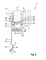
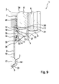
- FIGS. 2 to 9 Seven embodiments of an injection valve 1 are shown. In this case, the injection valve is shown in half section. Identical or functionally identical components are provided with the same reference numerals in all embodiments.
- FIG. 2 shows an injection valve 1 according to the first embodiment. Shown is the half-section to a central axis 2 of the injection valve 1.
- the injection valve 1 comprises a housing 3 with a magnet pot 4 and at least one injection opening 5.
- an inner pole 6 is mounted in the housing 3.
- the inner pole 6 is arranged stationary relative to the housing 3.
- the inner pole 6 is designed annular.
- a valve needle 9 is guided linearly movable along the central axis 2.
- the valve needle 9 comprises a spherical valve closing body 17. This valve closing body 17 forms, together with the housing 3, a valve seat 33. Furthermore, the valve needle 9 is at least partially hollow inside.
- the side wall of the valve needle 9 is interrupted with at least one flow opening 10. Furthermore, the valve needle 9 comprises a stop ring 18 and a stop sleeve 19.
- the injection valve 1 comprises a magnet armature 27.
- the armature 27 is linearly movable relative to the valve needle 9 and relative to the housing 3 along the central axis 2.
- the magnet armature 27 comprises a spring cup 28.
- a first return spring 29 is arranged between the adjusting sleeve 7 and the stop ring 18. Between the spring cup 28 and the stop sleeve 19, a second return spring 30 is arranged. The first Return spring 29 and the second return spring 30 are formed as compression springs.
- an upper guide 31 is formed between the magnet armature 27 and the housing 3, between the magnet armature 27 and the housing 3, an upper guide 31 is formed.
- the valve needle 9 is linearly guided here relative to the magnet armature 27, so that the upper guide 31 serves both for guiding the magnet armature 27 and for guiding the valve needle 9.
- a lower guide 23 for guiding the valve closing body 17 is formed in the lower region of the housing 2.
- a first recess 35 is provided at the inner pole 6 facing side of the armature 27, a first recess 35 is provided.
- the first recess 35 is dimensioned according to the stop ring 18, so that the stop ring is at least partially received in the first recess 35.
- the first return spring 29 loads the valve needle 9 in the direction of the valve seat 33 and thus leads to closing of the valve seat 33.
- the second return spring 30 loads the spring cup 28 and thus the armature 27 in the direction of the stop sleeve 19.
- the inner pole 6 is magnetized and thus attracts the magnet armature 27 at.
- the magnet armature 27 takes on the stop ring 18, the valve needle 9 with.
- the valve closing body 17 can lift off from the spray opening 5. In this case, the fuel flows through the hollow valve needle 9 and the throughflow opening 10 to the injection opening 5 and through the injection opening 5 into the combustion chamber of an internal combustion engine.
- a first stop surface 11 is defined at a valve seat 33 facing side of the inner pole 6, a first stop surface 11 is defined. The first stop surface 11 is located opposite a second stop surface 12 on the stop ring 18. At the valve seat 33 facing side of the stop ring 18, a third stop surface 13 is defined. The third stop surface 13 is located on the magnet armature 27 a fourth stop surface 14 against. At the valve seat 33 side facing the armature 27, a fifth stop surface 15 is formed. The fifth stop surface 15 is located opposite a sixth stop surface 16 on the stop sleeve 19.
- FIG. 3 shows a diagram of the injection valve 1 according to all embodiments. Similar to in FIG. 1 is shown in the upper section 20 of the current waveform 23 to the coil 8.
- the middle section 21 shows the course of Ventilnadelhubes 24 as a solid line.
- the course of the Magnetankerhubes 25 is shown with a dashed line.
- FIG. 1 The ballistic flight curve of the valve needle 9, after the magnet armature 27 has reached its position next possible at the inner pole 6, deleted. Due to the abutment between the first and second abutment surface 11, 12, the Ventilnadelhubterrorism can be controlled very precisely and thus also the amount of fuel to be dispensed can be specified very accurately.
- FIG. 4 shows the injection valve 1 according to a second embodiment.
- a second recess 36 is formed for the stop ring 18 in the inner embodiment 6 in the second embodiment.
- the first stop surface 11 is formed in this second recess 36.
- the upper guide 31 is formed between a plane parallel to the central axis 2 surface of the second recess 36 and the stop ring 18.
- the magnet armature 27 is guided on the valve needle 9.
- the valve needle 9 is guided over the stop ring 18 in the second recess 36 of the inner pole 6.
- FIG. 5 shows the injection valve 1 according to a third embodiment.
- the second return spring 30 is supported at one end against the armature 27 and at the other end against a housing-fixed spring stopper 34.
- the upper guide 31 is formed here between the magnet armature 27 and the housing 3.
- FIG. 6 shows the injection valve 1 according to a fourth embodiment.
- the second return spring 30 is supported here relative to the housing-fixed spring stop 34.
- the second recess 36 such as in the second embodiment.
- the leadership of the valve needle 8 takes place here via the upper guide 31 within the second recess 36th
- FIG. 7 shows the injection valve 1 according to a fifth embodiment.
- the second return spring 30 is supported at one end against the stop sleeve 19 and at the other end against the spring cup 28, as in the first and second embodiments.
- the first recess 35 is omitted.
- the upper guide 31 between the stop ring 18 and the inner pole 6 is formed in the second recess 36.
- a further guide 37 can be formed between the armature 27 and the housing 3 for guiding the magnet armature 27.
- FIG. 8 shows the injection valve 1 according to a sixth embodiment.
- the sixth embodiment corresponds to the fifth embodiment except for an additional stop bush 38.
- the stop bush 38 is fixed to the housing.
- the adjusting sleeve 7 as a spring bearing for the first return spring 29 is attached to the first stop bush 38.
- the first stop surface 11 and the second recess 36 are located on the first stop bush 38.
- FIG. 9 shows the injection valve 1 according to a seventh embodiment.
- the first stop bush 38 is formed without the second recess 36.
- the magnet armature 27 comprises a second stop bushing 39. On one side of the second stop bushing 39, the first recess 35 and the fourth stop surface 14 are formed.
- the upper guide 31 is formed between the armature 27 and the housing 3.
Landscapes
- Engineering & Computer Science (AREA)
- Chemical & Material Sciences (AREA)
- Combustion & Propulsion (AREA)
- Mechanical Engineering (AREA)
- General Engineering & Computer Science (AREA)
- Physics & Mathematics (AREA)
- Electromagnetism (AREA)
- Fuel-Injection Apparatus (AREA)
Claims (7)
- Soupape d'injection (1), en particulier pour l'injection de carburant dans un moteur à combustion interne, comportant- un boîtier (3) comprenant au moins une ouverture d'injection (5),- un pôle interne (6) fixe par rapport au boîtier (3), lequel pôle interne constitue par conséquent un composant solidaire du boîtier,- une bobine magnétique (8) agissant de manière magnétique sur le pôle interne (6),- une armature magnétique (27) mobile linéairement par rapport au boîtier,- une aiguille de soupape (9) mobile linéairement par rapport au boîtier (3) et par rapport à l'armature magnétique (27), laquelle aiguille de soupape forme, conjointement avec le boîtier (3), un siège de soupape (33),- une première surface de butée (11) fixe par rapport au boîtier (3) et- une deuxième surface de butée (12) réalisée sur l'aiguille de soupape (9), la deuxième surface de butée (12) venant en butée contre la première surface de butée (11) dans une position finale de l'aiguille de soupape (9) avec une levée maximale de l'aiguille de soupape,
l'aiguille de soupape (9) comportant une bague de butée (18) entre le pôle interne (6) et l'armature magnétique (27), caractérisée en ce que, dans le pôle interne (6) ou dans une douille de butée (38) installée dans le pôle interne (6), est prévu un évidement (36) comportant la première surface de butée (11) pour la réception de la bague de butée (18) et pour le guidage linéaire de la bague de butée (18) et par conséquent pour le guidage linéaire de l'aiguille de soupape (9). - Soupape d'injection selon la revendication 1, caractérisée par un premier ressort de rappel (29) entre le pôle interne (6) et l'aiguille de soupape (9).
- Soupape d'injection selon l'une quelconque des revendications précédentes, caractérisée en ce qu'une troisième surface de butée (13) tournée vers le siège de soupape (33) est réalisée sur l'aiguille de soupape (9), et une quatrième surface de butée (14) opposée au siège de soupape (33) est réalisée sur l'armature magnétique (27), la troisième surface de butée (13) et la quatrième surface de butée (14) venant en butée l'une contre l'autre lors du déplacement de l'aiguille de soupape (9).
- Soupape d'injection selon l'une quelconque des revendications précédentes, caractérisée par un deuxième ressort de rappel (30) entre l'armature magnétique (27) et l'aiguille de soupape (9) ou entre l'armature magnétique (27) et le boîtier (3).
- Soupape d'injection selon l'une quelconque des revendications précédentes, caractérisée en ce qu'une cinquième surface de butée (15) tournée vers le siège de soupape (33) est réalisée sur l'armature magnétique (27), et une sixième surface de butée (16) opposée au siège de soupape (33) est réalisée sur l'aiguille de soupape (9), la cinquième surface de butée (15) et la sixième surface de butée (16) venant en butée l'une contre l'autre lors du déplacement de l'aiguille de soupape (9).
- Soupape d'injection selon la revendication 1, caractérisée en ce que l'armature magnétique (27) comporte un évidement (35) pour la réception de la bague de butée (18).
- Soupape d'injection selon l'une quelconque des revendications précédentes, caractérisée en ce que l'armature magnétique (27) est guidée linéairement sur l'aiguille de soupape (9) et/ou sur le boîtier (3).
Applications Claiming Priority (1)
| Application Number | Priority Date | Filing Date | Title |
|---|---|---|---|
| DE102012203124A DE102012203124A1 (de) | 2012-02-29 | 2012-02-29 | Einspritzventil |
Publications (2)
| Publication Number | Publication Date |
|---|---|
| EP2634412A1 EP2634412A1 (fr) | 2013-09-04 |
| EP2634412B1 true EP2634412B1 (fr) | 2015-03-18 |
Family
ID=47683550
Family Applications (1)
| Application Number | Title | Priority Date | Filing Date |
|---|---|---|---|
| EP13152703.8A Not-in-force EP2634412B1 (fr) | 2012-02-29 | 2013-01-25 | Ventilateur d'injection |
Country Status (3)
| Country | Link |
|---|---|
| US (1) | US20130221138A1 (fr) |
| EP (1) | EP2634412B1 (fr) |
| DE (1) | DE102012203124A1 (fr) |
Families Citing this family (15)
| Publication number | Priority date | Publication date | Assignee | Title |
|---|---|---|---|---|
| KR101345431B1 (ko) * | 2011-12-09 | 2013-12-27 | 주식회사 현대케피코 | 직분사 연료 인젝터 |
| JP5982210B2 (ja) * | 2012-07-27 | 2016-08-31 | 日立オートモティブシステムズ株式会社 | 電磁式燃料噴射弁 |
| WO2015039859A1 (fr) * | 2013-09-18 | 2015-03-26 | Continental Automotive Gmbh | Ensemble de soupape pour une soupape d'injection et soupape d'injection |
| EP2851551B1 (fr) * | 2013-09-20 | 2016-05-25 | Continental Automotive GmbH | Soupape d'injection de fluide |
| EP2863042B1 (fr) * | 2013-10-15 | 2016-06-22 | Continental Automotive GmbH | Soupape d'injection |
| WO2016042753A1 (fr) * | 2014-09-17 | 2016-03-24 | 株式会社デンソー | Soupape d'injection de carburant |
| DE102014220100B3 (de) * | 2014-10-02 | 2016-01-28 | Continental Automotive Gmbh | Kraftstoffeinspritzventil und Verfahren zum Herstellen eines solchen |
| EP3009658B1 (fr) * | 2014-10-15 | 2017-09-06 | Continental Automotive GmbH | Injecteur pour injection de fluides |
| WO2016121475A1 (fr) * | 2015-01-30 | 2016-08-04 | 日立オートモティブシステムズ株式会社 | Robinet d'injection de carburant |
| EP3263884B8 (fr) | 2016-06-30 | 2019-12-18 | CPT Group GmbH | Soupape d'injection avec un élément de bague magnétique |
| JP6655723B2 (ja) * | 2016-08-26 | 2020-02-26 | 日立オートモティブシステムズ株式会社 | 燃料噴射弁 |
| EP3339626A1 (fr) * | 2016-12-23 | 2018-06-27 | Continental Automotive GmbH | Ensemble de soupape comprenant une armature avec surfaces de guidage et passages d'écoulement et soupape d'injection |
| US10240554B2 (en) | 2017-05-16 | 2019-03-26 | Ford Global Technologies, Llc | Methods and systems for adjusting a direct fuel injector |
| US10450997B2 (en) * | 2017-05-16 | 2019-10-22 | Ford Global Technologies, Llc | Methods and systems for adjusting a direct fuel injector and a port fuel injector |
| DE102018201951A1 (de) * | 2018-02-08 | 2019-08-08 | Robert Bosch Gmbh | Ventil zum Zumessen eines Fluids |
Family Cites Families (12)
| Publication number | Priority date | Publication date | Assignee | Title |
|---|---|---|---|---|
| DE3641469C2 (de) * | 1986-12-04 | 1994-02-10 | Bosch Gmbh Robert | Elektromagnetisch betätigbares Kraftstoffeinspritzventil |
| DE3642311A1 (de) * | 1986-12-11 | 1988-06-23 | Bosch Gmbh Robert | Elektromagnetisch betaetigbares kraftstoffeinspritzventil |
| EP0745764B1 (fr) * | 1995-06-02 | 2001-03-21 | Ganser-Hydromag Ag | Soupape d'injection de combustible pour moteurs à combustion interne |
| DE10039083A1 (de) * | 2000-08-10 | 2002-02-21 | Bosch Gmbh Robert | Brennstoffeinspritzventil |
| DE10108945A1 (de) | 2001-02-24 | 2002-09-05 | Bosch Gmbh Robert | Brennstoffeinspritzventil |
| DE10136808A1 (de) * | 2001-07-27 | 2003-02-13 | Bosch Gmbh Robert | Brennstoffeinspritzventil |
| KR100730841B1 (ko) * | 2003-06-04 | 2007-06-20 | 봇슈 가부시키가이샤 | 연료 분사 장치 |
| DE102004024533A1 (de) * | 2004-05-18 | 2005-12-15 | Robert Bosch Gmbh | Brennstoffeinspritzventil |
| DE102005052255B4 (de) * | 2005-11-02 | 2020-12-17 | Robert Bosch Gmbh | Brennstoffeinspritzventil |
| DE102005061424A1 (de) * | 2005-12-22 | 2007-07-05 | Robert Bosch Gmbh | Brennstoffeinspritzventil |
| US8215573B2 (en) * | 2010-05-14 | 2012-07-10 | Continental Automotive Systems Us, Inc. | Automotive gasoline solenoid double pole direct injector |
| JP5768536B2 (ja) * | 2010-10-05 | 2015-08-26 | 株式会社デンソー | 燃料噴射弁 |
-
2012
- 2012-02-29 DE DE102012203124A patent/DE102012203124A1/de not_active Withdrawn
-
2013
- 2013-01-25 EP EP13152703.8A patent/EP2634412B1/fr not_active Not-in-force
- 2013-02-28 US US13/780,665 patent/US20130221138A1/en not_active Abandoned
Also Published As
| Publication number | Publication date |
|---|---|
| US20130221138A1 (en) | 2013-08-29 |
| EP2634412A1 (fr) | 2013-09-04 |
| DE102012203124A1 (de) | 2013-08-29 |
Similar Documents
| Publication | Publication Date | Title |
|---|---|---|
| EP2634412B1 (fr) | Ventilateur d'injection | |
| EP2634413B1 (fr) | Injecteur | |
| EP2079922B1 (fr) | Injecteur d'injection de carburant | |
| DE102007060395A1 (de) | Schaltventil für Injektoren | |
| EP2901004A1 (fr) | Soupape d'injection | |
| EP1390614B1 (fr) | Electrovanne de commande de soupape d'injection de moteur a combustion interne | |
| EP3478957A1 (fr) | Soupape d'injection d'un carburant gazeux | |
| DE102016220326A1 (de) | Ventil zum Zumessen eines gasförmigen oder flüssigen Kraftstoffs | |
| WO2015106935A1 (fr) | Pompe à haute pression munie d'une soupape d'aspiration électromagnétique | |
| DE102005053115A1 (de) | Optimierte Ankergruppenführung für Magnetventile | |
| WO2011006707A1 (fr) | Système de soupape | |
| WO2009124789A1 (fr) | Électrovanne sans disque d'entrefer résiduel | |
| DE102007011047A1 (de) | Magnetventilinjektor | |
| DE102012201413A1 (de) | Magnetventil für einen Kraftstoffinjektor | |
| WO2019137680A1 (fr) | Soupape de dosage d'un fluide | |
| EP2314860B1 (fr) | Injecteur de carburant | |
| DE102006020724A1 (de) | Magnetventil mit selbstzentrierendem Ankerbolzen | |
| EP2426348B1 (fr) | Soupape d'injection de combustible | |
| EP3374625A1 (fr) | Soupape d'aspiration à commande électromagnétique pour pompe à haute pression et pompe à haute pression | |
| EP2147206B1 (fr) | Injecteur de carburant avec électrovanne | |
| DE102014226367A1 (de) | Brennstoffeinspritzventil | |
| EP3346121B1 (fr) | Électrovanne pour un système d'injection de carburant et pompe haute pression à carburant | |
| DE102008000697A1 (de) | Schaltventil für Injektoren | |
| DE102015213221A1 (de) | Ventil zum Zumessen eines Fluids | |
| DE102013224090A1 (de) | Kraftstoffinjektor |
Legal Events
| Date | Code | Title | Description |
|---|---|---|---|
| PUAI | Public reference made under article 153(3) epc to a published international application that has entered the european phase |
Free format text: ORIGINAL CODE: 0009012 |
|
| AK | Designated contracting states |
Kind code of ref document: A1 Designated state(s): AL AT BE BG CH CY CZ DE DK EE ES FI FR GB GR HR HU IE IS IT LI LT LU LV MC MK MT NL NO PL PT RO RS SE SI SK SM TR |
|
| AX | Request for extension of the european patent |
Extension state: BA ME |
|
| 17P | Request for examination filed |
Effective date: 20140304 |
|
| RBV | Designated contracting states (corrected) |
Designated state(s): AL AT BE BG CH CY CZ DE DK EE ES FI FR GB GR HR HU IE IS IT LI LT LU LV MC MK MT NL NO PL PT RO RS SE SI SK SM TR |
|
| GRAP | Despatch of communication of intention to grant a patent |
Free format text: ORIGINAL CODE: EPIDOSNIGR1 |
|
| INTG | Intention to grant announced |
Effective date: 20141113 |
|
| GRAS | Grant fee paid |
Free format text: ORIGINAL CODE: EPIDOSNIGR3 |
|
| GRAA | (expected) grant |
Free format text: ORIGINAL CODE: 0009210 |
|
| AK | Designated contracting states |
Kind code of ref document: B1 Designated state(s): AL AT BE BG CH CY CZ DE DK EE ES FI FR GB GR HR HU IE IS IT LI LT LU LV MC MK MT NL NO PL PT RO RS SE SI SK SM TR |
|
| REG | Reference to a national code |
Ref country code: GB Ref legal event code: FG4D Free format text: NOT ENGLISH |
|
| REG | Reference to a national code |
Ref country code: CH Ref legal event code: EP |
|
| REG | Reference to a national code |
Ref country code: IE Ref legal event code: FG4D Free format text: LANGUAGE OF EP DOCUMENT: GERMAN |
|
| REG | Reference to a national code |
Ref country code: AT Ref legal event code: REF Ref document number: 716756 Country of ref document: AT Kind code of ref document: T Effective date: 20150415 |
|
| REG | Reference to a national code |
Ref country code: DE Ref legal event code: R096 Ref document number: 502013000469 Country of ref document: DE Effective date: 20150430 |
|
| REG | Reference to a national code |
Ref country code: NL Ref legal event code: VDEP Effective date: 20150318 |
|
| REG | Reference to a national code |
Ref country code: NL Ref legal event code: VDEP Effective date: 20150318 |
|
| PG25 | Lapsed in a contracting state [announced via postgrant information from national office to epo] |
Ref country code: HR Free format text: LAPSE BECAUSE OF FAILURE TO SUBMIT A TRANSLATION OF THE DESCRIPTION OR TO PAY THE FEE WITHIN THE PRESCRIBED TIME-LIMIT Effective date: 20150318 Ref country code: NO Free format text: LAPSE BECAUSE OF FAILURE TO SUBMIT A TRANSLATION OF THE DESCRIPTION OR TO PAY THE FEE WITHIN THE PRESCRIBED TIME-LIMIT Effective date: 20150618 Ref country code: FI Free format text: LAPSE BECAUSE OF FAILURE TO SUBMIT A TRANSLATION OF THE DESCRIPTION OR TO PAY THE FEE WITHIN THE PRESCRIBED TIME-LIMIT Effective date: 20150318 Ref country code: LT Free format text: LAPSE BECAUSE OF FAILURE TO SUBMIT A TRANSLATION OF THE DESCRIPTION OR TO PAY THE FEE WITHIN THE PRESCRIBED TIME-LIMIT Effective date: 20150318 Ref country code: SE Free format text: LAPSE BECAUSE OF FAILURE TO SUBMIT A TRANSLATION OF THE DESCRIPTION OR TO PAY THE FEE WITHIN THE PRESCRIBED TIME-LIMIT Effective date: 20150318 |
|
| REG | Reference to a national code |
Ref country code: LT Ref legal event code: MG4D |
|
| PG25 | Lapsed in a contracting state [announced via postgrant information from national office to epo] |
Ref country code: LV Free format text: LAPSE BECAUSE OF FAILURE TO SUBMIT A TRANSLATION OF THE DESCRIPTION OR TO PAY THE FEE WITHIN THE PRESCRIBED TIME-LIMIT Effective date: 20150318 Ref country code: RS Free format text: LAPSE BECAUSE OF FAILURE TO SUBMIT A TRANSLATION OF THE DESCRIPTION OR TO PAY THE FEE WITHIN THE PRESCRIBED TIME-LIMIT Effective date: 20150318 Ref country code: GR Free format text: LAPSE BECAUSE OF FAILURE TO SUBMIT A TRANSLATION OF THE DESCRIPTION OR TO PAY THE FEE WITHIN THE PRESCRIBED TIME-LIMIT Effective date: 20150619 |
|
| PG25 | Lapsed in a contracting state [announced via postgrant information from national office to epo] |
Ref country code: NL Free format text: LAPSE BECAUSE OF FAILURE TO SUBMIT A TRANSLATION OF THE DESCRIPTION OR TO PAY THE FEE WITHIN THE PRESCRIBED TIME-LIMIT Effective date: 20150318 |
|
| PG25 | Lapsed in a contracting state [announced via postgrant information from national office to epo] |
Ref country code: SK Free format text: LAPSE BECAUSE OF FAILURE TO SUBMIT A TRANSLATION OF THE DESCRIPTION OR TO PAY THE FEE WITHIN THE PRESCRIBED TIME-LIMIT Effective date: 20150318 Ref country code: RO Free format text: LAPSE BECAUSE OF FAILURE TO SUBMIT A TRANSLATION OF THE DESCRIPTION OR TO PAY THE FEE WITHIN THE PRESCRIBED TIME-LIMIT Effective date: 20150318 Ref country code: EE Free format text: LAPSE BECAUSE OF FAILURE TO SUBMIT A TRANSLATION OF THE DESCRIPTION OR TO PAY THE FEE WITHIN THE PRESCRIBED TIME-LIMIT Effective date: 20150318 Ref country code: PT Free format text: LAPSE BECAUSE OF FAILURE TO SUBMIT A TRANSLATION OF THE DESCRIPTION OR TO PAY THE FEE WITHIN THE PRESCRIBED TIME-LIMIT Effective date: 20150720 Ref country code: CZ Free format text: LAPSE BECAUSE OF FAILURE TO SUBMIT A TRANSLATION OF THE DESCRIPTION OR TO PAY THE FEE WITHIN THE PRESCRIBED TIME-LIMIT Effective date: 20150318 Ref country code: ES Free format text: LAPSE BECAUSE OF FAILURE TO SUBMIT A TRANSLATION OF THE DESCRIPTION OR TO PAY THE FEE WITHIN THE PRESCRIBED TIME-LIMIT Effective date: 20150318 |
|
| PG25 | Lapsed in a contracting state [announced via postgrant information from national office to epo] |
Ref country code: PL Free format text: LAPSE BECAUSE OF FAILURE TO SUBMIT A TRANSLATION OF THE DESCRIPTION OR TO PAY THE FEE WITHIN THE PRESCRIBED TIME-LIMIT Effective date: 20150318 Ref country code: IS Free format text: LAPSE BECAUSE OF FAILURE TO SUBMIT A TRANSLATION OF THE DESCRIPTION OR TO PAY THE FEE WITHIN THE PRESCRIBED TIME-LIMIT Effective date: 20150718 |
|
| REG | Reference to a national code |
Ref country code: DE Ref legal event code: R097 Ref document number: 502013000469 Country of ref document: DE |
|
| REG | Reference to a national code |
Ref country code: FR Ref legal event code: PLFP Year of fee payment: 4 |
|
| PLBE | No opposition filed within time limit |
Free format text: ORIGINAL CODE: 0009261 |
|
| STAA | Information on the status of an ep patent application or granted ep patent |
Free format text: STATUS: NO OPPOSITION FILED WITHIN TIME LIMIT |
|
| PG25 | Lapsed in a contracting state [announced via postgrant information from national office to epo] |
Ref country code: DK Free format text: LAPSE BECAUSE OF FAILURE TO SUBMIT A TRANSLATION OF THE DESCRIPTION OR TO PAY THE FEE WITHIN THE PRESCRIBED TIME-LIMIT Effective date: 20150318 |
|
| 26N | No opposition filed |
Effective date: 20151221 |
|
| PG25 | Lapsed in a contracting state [announced via postgrant information from national office to epo] |
Ref country code: SI Free format text: LAPSE BECAUSE OF FAILURE TO SUBMIT A TRANSLATION OF THE DESCRIPTION OR TO PAY THE FEE WITHIN THE PRESCRIBED TIME-LIMIT Effective date: 20150318 |
|
| PG25 | Lapsed in a contracting state [announced via postgrant information from national office to epo] |
Ref country code: BE Free format text: LAPSE BECAUSE OF NON-PAYMENT OF DUE FEES Effective date: 20160131 |
|
| PG25 | Lapsed in a contracting state [announced via postgrant information from national office to epo] |
Ref country code: LU Free format text: LAPSE BECAUSE OF FAILURE TO SUBMIT A TRANSLATION OF THE DESCRIPTION OR TO PAY THE FEE WITHIN THE PRESCRIBED TIME-LIMIT Effective date: 20160125 |
|
| REG | Reference to a national code |
Ref country code: CH Ref legal event code: PL |
|
| PG25 | Lapsed in a contracting state [announced via postgrant information from national office to epo] |
Ref country code: MC Free format text: LAPSE BECAUSE OF FAILURE TO SUBMIT A TRANSLATION OF THE DESCRIPTION OR TO PAY THE FEE WITHIN THE PRESCRIBED TIME-LIMIT Effective date: 20150318 |
|
| PG25 | Lapsed in a contracting state [announced via postgrant information from national office to epo] |
Ref country code: CH Free format text: LAPSE BECAUSE OF NON-PAYMENT OF DUE FEES Effective date: 20160131 Ref country code: LI Free format text: LAPSE BECAUSE OF NON-PAYMENT OF DUE FEES Effective date: 20160131 |
|
| REG | Reference to a national code |
Ref country code: IE Ref legal event code: MM4A |
|
| REG | Reference to a national code |
Ref country code: FR Ref legal event code: PLFP Year of fee payment: 5 |
|
| PG25 | Lapsed in a contracting state [announced via postgrant information from national office to epo] |
Ref country code: IE Free format text: LAPSE BECAUSE OF NON-PAYMENT OF DUE FEES Effective date: 20160125 |
|
| PG25 | Lapsed in a contracting state [announced via postgrant information from national office to epo] |
Ref country code: MT Free format text: LAPSE BECAUSE OF FAILURE TO SUBMIT A TRANSLATION OF THE DESCRIPTION OR TO PAY THE FEE WITHIN THE PRESCRIBED TIME-LIMIT Effective date: 20150318 |
|
| GBPC | Gb: european patent ceased through non-payment of renewal fee |
Effective date: 20170125 |
|
| PG25 | Lapsed in a contracting state [announced via postgrant information from national office to epo] |
Ref country code: GB Free format text: LAPSE BECAUSE OF NON-PAYMENT OF DUE FEES Effective date: 20170125 |
|
| REG | Reference to a national code |
Ref country code: FR Ref legal event code: PLFP Year of fee payment: 6 |
|
| PG25 | Lapsed in a contracting state [announced via postgrant information from national office to epo] |
Ref country code: CY Free format text: LAPSE BECAUSE OF FAILURE TO SUBMIT A TRANSLATION OF THE DESCRIPTION OR TO PAY THE FEE WITHIN THE PRESCRIBED TIME-LIMIT Effective date: 20150318 Ref country code: HU Free format text: LAPSE BECAUSE OF FAILURE TO SUBMIT A TRANSLATION OF THE DESCRIPTION OR TO PAY THE FEE WITHIN THE PRESCRIBED TIME-LIMIT; INVALID AB INITIO Effective date: 20130125 Ref country code: SM Free format text: LAPSE BECAUSE OF FAILURE TO SUBMIT A TRANSLATION OF THE DESCRIPTION OR TO PAY THE FEE WITHIN THE PRESCRIBED TIME-LIMIT Effective date: 20150318 |
|
| PG25 | Lapsed in a contracting state [announced via postgrant information from national office to epo] |
Ref country code: MK Free format text: LAPSE BECAUSE OF FAILURE TO SUBMIT A TRANSLATION OF THE DESCRIPTION OR TO PAY THE FEE WITHIN THE PRESCRIBED TIME-LIMIT Effective date: 20150318 Ref country code: TR Free format text: LAPSE BECAUSE OF FAILURE TO SUBMIT A TRANSLATION OF THE DESCRIPTION OR TO PAY THE FEE WITHIN THE PRESCRIBED TIME-LIMIT Effective date: 20150318 |
|
| PG25 | Lapsed in a contracting state [announced via postgrant information from national office to epo] |
Ref country code: BG Free format text: LAPSE BECAUSE OF FAILURE TO SUBMIT A TRANSLATION OF THE DESCRIPTION OR TO PAY THE FEE WITHIN THE PRESCRIBED TIME-LIMIT Effective date: 20150318 |
|
| PG25 | Lapsed in a contracting state [announced via postgrant information from national office to epo] |
Ref country code: AL Free format text: LAPSE BECAUSE OF FAILURE TO SUBMIT A TRANSLATION OF THE DESCRIPTION OR TO PAY THE FEE WITHIN THE PRESCRIBED TIME-LIMIT Effective date: 20150318 |
|
| REG | Reference to a national code |
Ref country code: AT Ref legal event code: MM01 Ref document number: 716756 Country of ref document: AT Kind code of ref document: T Effective date: 20180125 |
|
| PG25 | Lapsed in a contracting state [announced via postgrant information from national office to epo] |
Ref country code: AT Free format text: LAPSE BECAUSE OF NON-PAYMENT OF DUE FEES Effective date: 20180125 |
|
| PGFP | Annual fee paid to national office [announced via postgrant information from national office to epo] |
Ref country code: IT Payment date: 20210129 Year of fee payment: 9 Ref country code: FR Payment date: 20210120 Year of fee payment: 9 |
|
| PG25 | Lapsed in a contracting state [announced via postgrant information from national office to epo] |
Ref country code: FR Free format text: LAPSE BECAUSE OF NON-PAYMENT OF DUE FEES Effective date: 20220131 |
|
| PG25 | Lapsed in a contracting state [announced via postgrant information from national office to epo] |
Ref country code: IT Free format text: LAPSE BECAUSE OF NON-PAYMENT OF DUE FEES Effective date: 20220125 |
|
| PGFP | Annual fee paid to national office [announced via postgrant information from national office to epo] |
Ref country code: DE Payment date: 20230324 Year of fee payment: 11 |
|
| REG | Reference to a national code |
Ref country code: DE Ref legal event code: R119 Ref document number: 502013000469 Country of ref document: DE |
|
| PG25 | Lapsed in a contracting state [announced via postgrant information from national office to epo] |
Ref country code: DE Free format text: LAPSE BECAUSE OF NON-PAYMENT OF DUE FEES Effective date: 20240801 |
|
| PG25 | Lapsed in a contracting state [announced via postgrant information from national office to epo] |
Ref country code: DE Free format text: LAPSE BECAUSE OF NON-PAYMENT OF DUE FEES Effective date: 20240801 |