EP2634419B1 - Procédé de fonctionnement d'une éolienne - Google Patents
Procédé de fonctionnement d'une éolienne Download PDFInfo
- Publication number
- EP2634419B1 EP2634419B1 EP12382077.1A EP12382077A EP2634419B1 EP 2634419 B1 EP2634419 B1 EP 2634419B1 EP 12382077 A EP12382077 A EP 12382077A EP 2634419 B1 EP2634419 B1 EP 2634419B1
- Authority
- EP
- European Patent Office
- Prior art keywords
- blades
- blade
- wind turbine
- moment
- pitching
- Prior art date
- Legal status (The legal status is an assumption and is not a legal conclusion. Google has not performed a legal analysis and makes no representation as to the accuracy of the status listed.)
- Not-in-force
Links
- 238000000034 method Methods 0.000 title claims description 34
- 230000007246 mechanism Effects 0.000 claims description 13
- 230000007935 neutral effect Effects 0.000 claims description 11
- 230000007423 decrease Effects 0.000 claims description 8
- 230000000694 effects Effects 0.000 description 5
- 235000009413 Ratibida columnifera Nutrition 0.000 description 2
- 241000510442 Ratibida peduncularis Species 0.000 description 2
- 238000005452 bending Methods 0.000 description 2
- 230000003247 decreasing effect Effects 0.000 description 2
- 230000005611 electricity Effects 0.000 description 2
- 238000013528 artificial neural network Methods 0.000 description 1
- 238000011217 control strategy Methods 0.000 description 1
- 238000001514 detection method Methods 0.000 description 1
- 238000005516 engineering process Methods 0.000 description 1
- 238000012423 maintenance Methods 0.000 description 1
- 238000012986 modification Methods 0.000 description 1
- 230000004048 modification Effects 0.000 description 1
- 230000003287 optical effect Effects 0.000 description 1
Images




Classifications
-
- F—MECHANICAL ENGINEERING; LIGHTING; HEATING; WEAPONS; BLASTING
- F03—MACHINES OR ENGINES FOR LIQUIDS; WIND, SPRING, OR WEIGHT MOTORS; PRODUCING MECHANICAL POWER OR A REACTIVE PROPULSIVE THRUST, NOT OTHERWISE PROVIDED FOR
- F03D—WIND MOTORS
- F03D7/00—Controlling wind motors
- F03D7/02—Controlling wind motors the wind motors having rotation axis substantially parallel to the air flow entering the rotor
- F03D7/022—Adjusting aerodynamic properties of the blades
- F03D7/0224—Adjusting blade pitch
-
- F—MECHANICAL ENGINEERING; LIGHTING; HEATING; WEAPONS; BLASTING
- F03—MACHINES OR ENGINES FOR LIQUIDS; WIND, SPRING, OR WEIGHT MOTORS; PRODUCING MECHANICAL POWER OR A REACTIVE PROPULSIVE THRUST, NOT OTHERWISE PROVIDED FOR
- F03D—WIND MOTORS
- F03D7/00—Controlling wind motors
- F03D7/02—Controlling wind motors the wind motors having rotation axis substantially parallel to the air flow entering the rotor
- F03D7/022—Adjusting aerodynamic properties of the blades
- F03D7/0232—Adjusting aerodynamic properties of the blades with flaps or slats
-
- F—MECHANICAL ENGINEERING; LIGHTING; HEATING; WEAPONS; BLASTING
- F05—INDEXING SCHEMES RELATING TO ENGINES OR PUMPS IN VARIOUS SUBCLASSES OF CLASSES F01-F04
- F05B—INDEXING SCHEME RELATING TO WIND, SPRING, WEIGHT, INERTIA OR LIKE MOTORS, TO MACHINES OR ENGINES FOR LIQUIDS COVERED BY SUBCLASSES F03B, F03D AND F03G
- F05B2240/00—Components
- F05B2240/20—Rotors
- F05B2240/30—Characteristics of rotor blades, i.e. of any element transforming dynamic fluid energy to or from rotational energy and being attached to a rotor
- F05B2240/305—Flaps, slats or spoilers
- F05B2240/3052—Flaps, slats or spoilers adjustable
-
- F—MECHANICAL ENGINEERING; LIGHTING; HEATING; WEAPONS; BLASTING
- F05—INDEXING SCHEMES RELATING TO ENGINES OR PUMPS IN VARIOUS SUBCLASSES OF CLASSES F01-F04
- F05B—INDEXING SCHEME RELATING TO WIND, SPRING, WEIGHT, INERTIA OR LIKE MOTORS, TO MACHINES OR ENGINES FOR LIQUIDS COVERED BY SUBCLASSES F03B, F03D AND F03G
- F05B2260/00—Function
- F05B2260/70—Adjusting of angle of incidence or attack of rotating blades
- F05B2260/76—Adjusting of angle of incidence or attack of rotating blades the adjusting mechanism using auxiliary power sources
-
- F—MECHANICAL ENGINEERING; LIGHTING; HEATING; WEAPONS; BLASTING
- F05—INDEXING SCHEMES RELATING TO ENGINES OR PUMPS IN VARIOUS SUBCLASSES OF CLASSES F01-F04
- F05B—INDEXING SCHEME RELATING TO WIND, SPRING, WEIGHT, INERTIA OR LIKE MOTORS, TO MACHINES OR ENGINES FOR LIQUIDS COVERED BY SUBCLASSES F03B, F03D AND F03G
- F05B2270/00—Control
- F05B2270/30—Control parameters, e.g. input parameters
- F05B2270/32—Wind speeds
-
- F—MECHANICAL ENGINEERING; LIGHTING; HEATING; WEAPONS; BLASTING
- F05—INDEXING SCHEMES RELATING TO ENGINES OR PUMPS IN VARIOUS SUBCLASSES OF CLASSES F01-F04
- F05B—INDEXING SCHEME RELATING TO WIND, SPRING, WEIGHT, INERTIA OR LIKE MOTORS, TO MACHINES OR ENGINES FOR LIQUIDS COVERED BY SUBCLASSES F03B, F03D AND F03G
- F05B2270/00—Control
- F05B2270/30—Control parameters, e.g. input parameters
- F05B2270/322—Control parameters, e.g. input parameters the detection or prediction of a wind gust
-
- F—MECHANICAL ENGINEERING; LIGHTING; HEATING; WEAPONS; BLASTING
- F05—INDEXING SCHEMES RELATING TO ENGINES OR PUMPS IN VARIOUS SUBCLASSES OF CLASSES F01-F04
- F05B—INDEXING SCHEME RELATING TO WIND, SPRING, WEIGHT, INERTIA OR LIKE MOTORS, TO MACHINES OR ENGINES FOR LIQUIDS COVERED BY SUBCLASSES F03B, F03D AND F03G
- F05B2270/00—Control
- F05B2270/30—Control parameters, e.g. input parameters
- F05B2270/328—Blade pitch angle
-
- F—MECHANICAL ENGINEERING; LIGHTING; HEATING; WEAPONS; BLASTING
- F05—INDEXING SCHEMES RELATING TO ENGINES OR PUMPS IN VARIOUS SUBCLASSES OF CLASSES F01-F04
- F05B—INDEXING SCHEME RELATING TO WIND, SPRING, WEIGHT, INERTIA OR LIKE MOTORS, TO MACHINES OR ENGINES FOR LIQUIDS COVERED BY SUBCLASSES F03B, F03D AND F03G
- F05B2270/00—Control
- F05B2270/30—Control parameters, e.g. input parameters
- F05B2270/331—Mechanical loads
-
- F—MECHANICAL ENGINEERING; LIGHTING; HEATING; WEAPONS; BLASTING
- F05—INDEXING SCHEMES RELATING TO ENGINES OR PUMPS IN VARIOUS SUBCLASSES OF CLASSES F01-F04
- F05B—INDEXING SCHEME RELATING TO WIND, SPRING, WEIGHT, INERTIA OR LIKE MOTORS, TO MACHINES OR ENGINES FOR LIQUIDS COVERED BY SUBCLASSES F03B, F03D AND F03G
- F05B2270/00—Control
- F05B2270/30—Control parameters, e.g. input parameters
- F05B2270/335—Output power or torque
-
- F—MECHANICAL ENGINEERING; LIGHTING; HEATING; WEAPONS; BLASTING
- F05—INDEXING SCHEMES RELATING TO ENGINES OR PUMPS IN VARIOUS SUBCLASSES OF CLASSES F01-F04
- F05B—INDEXING SCHEME RELATING TO WIND, SPRING, WEIGHT, INERTIA OR LIKE MOTORS, TO MACHINES OR ENGINES FOR LIQUIDS COVERED BY SUBCLASSES F03B, F03D AND F03G
- F05B2270/00—Control
- F05B2270/40—Type of control system
- F05B2270/404—Type of control system active, predictive, or anticipative
-
- F—MECHANICAL ENGINEERING; LIGHTING; HEATING; WEAPONS; BLASTING
- F05—INDEXING SCHEMES RELATING TO ENGINES OR PUMPS IN VARIOUS SUBCLASSES OF CLASSES F01-F04
- F05B—INDEXING SCHEME RELATING TO WIND, SPRING, WEIGHT, INERTIA OR LIKE MOTORS, TO MACHINES OR ENGINES FOR LIQUIDS COVERED BY SUBCLASSES F03B, F03D AND F03G
- F05B2270/00—Control
- F05B2270/80—Devices generating input signals, e.g. transducers, sensors, cameras or strain gauges
- F05B2270/804—Optical devices
- F05B2270/8042—Lidar systems
-
- Y—GENERAL TAGGING OF NEW TECHNOLOGICAL DEVELOPMENTS; GENERAL TAGGING OF CROSS-SECTIONAL TECHNOLOGIES SPANNING OVER SEVERAL SECTIONS OF THE IPC; TECHNICAL SUBJECTS COVERED BY FORMER USPC CROSS-REFERENCE ART COLLECTIONS [XRACs] AND DIGESTS
- Y02—TECHNOLOGIES OR APPLICATIONS FOR MITIGATION OR ADAPTATION AGAINST CLIMATE CHANGE
- Y02E—REDUCTION OF GREENHOUSE GAS [GHG] EMISSIONS, RELATED TO ENERGY GENERATION, TRANSMISSION OR DISTRIBUTION
- Y02E10/00—Energy generation through renewable energy sources
- Y02E10/70—Wind energy
- Y02E10/72—Wind turbines with rotation axis in wind direction
Definitions
- the present disclosure relates to a method of operating a wind turbine, and more particularly relates to a method of operating a wind turbine that comprises a plurality of blades, each of the blades being rotatable along its longitudinal axis, and each of the blades comprising one or more movable trailing edge surfaces, such as e.g flaps.
- Wind turbines are commonly used to supply electricity into the electrical grid.
- Wind turbines of this kind generally comprise a rotor with a rotor hub and a plurality of blades.
- the rotor is set into rotation under the influence of the wind on the blades.
- the rotation of the rotor shaft either directly drives the generator rotor ("directly driven") or through the use of a gearbox.
- blade loads such as e.g. the blade root bending moment may become more critical.
- the blade loads may be substantially affected by e.g. wind gusts, turbulence and wind shear. Changing wind velocities, and more particularly quickly changing wind velocities can especially affect the blade loads, and thereby impact the fatigue of various wind turbine components, such as e.g. the blades, hub, rotor shaft or gearbox.
- Pitch systems may be employed in wind turbines for adapting the position of a wind turbine blade to varying wind conditions by rotating the blade along its longitudinal axis.
- it is known to rotate a wind turbine blade in such a way that it generates less lift (and drag) when the wind speed increases. This way, even though the wind speed increases, the torque transmitted by the rotor to the generator remains substantially the same.
- It is furthermore also known to rotate wind turbine blades towards their stall position (so as to reduce the lift or the blades) when the wind speed increases. These wind turbines are sometimes referred to as "active-stall" wind turbines.
- Pitching may furthermore also be used for rotation of the blade towards its vane position, when a turbine is temporarily stopped or taken out of operation for e.g. maintenance.
- a common control strategy of a variable speed wind turbine is to maintain the blade in a predefined "below rated pitch position" at wind speeds equal to or below nominal wind speed (for example from approximately 3 or 4 m/s to 10 m/s).
- Said default pitch position may generally be close to a 0° pitch angle.
- the exact pitch angle in "below rated” conditions depends however on the complete design of the wind turbine.
- the objective is generally to maximize power output by maintaining pitch constant, thereby catching maximum energy, and varying generator torque and the rotor speed to keep the power coefficient, C p, at a maximum.
- Cut-in wind speed may e.g be around 3 m/s
- nominal wind speed may be e.g. around 10 m/s
- cut-out wind speed may e.g. be around 25 m/s.
- the nominal wind speed, cut-in wind speed and cut-out wind speed may of course vary depending on the wind turbine design.
- aerodynamic devices such as e.g. flaps, slats, spoilers, and Boundary Layer Control devices may be employed on blades of wind turbines in order to influence and control the aerodynamic flow around the blades. Flaps along the trailing edge of a blade can be actuated relatively quickly and have the capability of quickly modifying the lift and drag (loads) of a blade. Flaps may therefore be employed on larger wind turbine blades to quickly alleviate loads when needed.
- EP 2 109 203 discloses a wind turbine having at least a blade comprising a first component having an aerodynamic profile with a leading edge, a trailing edge and suction and pressure sides between the leading edge and the trailing edge and a second component attached to the trailing edge and/or to the leading edge of the first component in at least a part of the blade, in which the second component comprises an upwards and/or downwards deflectable flap that allows changing the flow over the blade.
- the blades comprise one or more flaps, and wherein the blades may be rotated substantially along their longitudinal axes by a pitch mechanism, a joint control of the various actuators is needed in order to make sure e.g. that loads stay within predefined limits, fatigue is limited and electrical power may be generated efficiently (at a relatively low Cost Of Energy).
- the present disclosure provides a method of operating a wind turbine comprising a plurality of blades, each of the blades being rotatable along its longitudinal axis using a pitch mechanism, and each of the blades comprising one or more movable trailing edge surfaces.
- the method comprises, at a first moment in time, predicting a high load for one or more of the blades at a second moment in time.
- the method further comprises, before the second moment in time, (i.e. before the predicted high load) actuating on one or more of the movable trailing edge surfaces of these blades such that they assume a position wherein they have a wider range of control to counteract the predicted high loads, and simultaneously pitching the blades such as not to negatively affect the operation of the wind turbine.
- the one or more movable trailing edge surfaces of the at least one or more blades may be actuated to counteract the high loads.
- a high load e.g. one or more flaps along a blade may be moved towards a position in which its control range is increased such that it can counteract the predicted high load when necessary. For example, if a flap is at its most negative position (wherein it reduces the lift of the blade), it may be moved towards its neutral position or even towards its most positive position (wherein it actually increases the lift of the blade). This in itself would lead to e.g. higher lift and higher drag. This may increase e.g. blade root bending moments and the aerodynamic torque of the wind turbine. To at least partially compensate for this modified flap position, a pitch mechanism may be used to reduce the angle of attack of the blades, and thereby reduce the lift (and drag). The combination of both measures will make sure that the operation of the wind turbine does not need to be affected in a substantial manner. And at the same time, it can be ensured that the flaps are in a position in which it can counteract the high loads quickly.
- the operational mode of the wind turbine may be to maximize the generation of electrical power.
- pitching the blades such as not to negatively affect the operation of the wind turbine may comprise pitching the blades such that the generation of electrical power is not negatively affected.
- Pitching the blades such as not to negatively affect the operation of the wind turbine may in certain circumstances also comprise pitching the blades such that the loads on the blades remain substantially at the same level as at the first moment in time.
- high loads may be predicted using a LIDAR system.
- a high load may be predicted by measuring the loads in the wind turbine itself or in a neighbouring wind turbine.
- the movable trailing edge surfaces may be flaps.
- each of the blades may comprise a plurality of flaps distributed along the length of the blade, and each of these flaps may be actuated individually.
- the pitch of the blade may not need to be changed a lot.
- the movable trailing edge surfaces may be Continuously Deformable Trailing Edge (CDTE) portions.
- CDTE Continuously Deformable Trailing Edge
- a high load may be predicted for a first blade at a second moment in time
- a high load may be predicted for a second blade at a third moment time.
- the flaps (or alternative movable trailing edge surface) of the first blade may be actuated such that they assume a position wherein they have a wider range of control to counteract the predicted high loads
- the flaps (or alternative movable trailing edge surface) of the second blade may be actuated such that they assume a position wherein they have a wider range of control to counteract the predicted high loads.
- the blades of the wind turbine may be pitched such that the operation of the wind turbine (e.g. the generation of electrical power or the loads on the blades) is substantially not negatively affected and at said second moment in time, the one or more flaps of the first blade are actuated so as to counteract the high loads, and at the third moment in time, the one or more flaps of the second blade may be actuated so as to counteract the high loads.
- the operation of the wind turbine e.g. the generation of electrical power or the loads on the blades
- the one or more flaps of the first blade are actuated so as to counteract the high loads
- the one or more flaps of the second blade may be actuated so as to counteract the high loads.
- the wind turbine may comprise a collective pitch mechanism for pitching all the blades together.
- the wind turbine may comprise an individual pitch system for each of the blades, such that each of the blades can be pitched individually.
- FIG. 1 a illustrates a wind turbine comprising a tower 9, and a rotor comprising a first blade 1, a second blade 2 and a third blade 3.
- the swept area of the rotor is indicated using reference sign 4.
- each of the blades may be rotated substantially along their longitudinal axes, using a collective pitch mechanism or three individual pitch mechanisms.
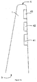
- Figure 1 b illustrates a top view of a wind turbine blade 1.
- the wind turbine blade extends from the blade root 5 to a blade tip 6.
- three flaps 41, 42, 43 have been provided along the trailing edge, substantially in an outer portion of the blade span. In other embodiments, more or less flaps may be provided. Additionally, in other embodiments, flaps may only be provided along an inner portion of the blade span, or alternatively flaps may be provided substantially along the entire blade span.
- FIG 1 c illustrates the use of a LIDAR 51 on a wind turbine.
- LIDAR stands for Light Detection and Ranging and involves an optical remote sensing technology that can measure the distance to, or other properties of a target by illuminating the target with light.
- LIDARs and specifically Doppler LIDARs are well known in the field of wind energy for measuring wind speeds ahead of a wind turbine and they will not be further described herein.
- LIDARs may be used to e.g. measure wind speeds, wind shear (as indicated with reference sign 52 in figure 1 c) , and local turbulences, e.g. the area indicated with reference sign 7 in figure 1 a.
- Figures 2a - 2c illustrate the effect of a flap on the lift coefficient and drag coefficient of an aerodynamic profile for different angles of attack and different flap positions.
- Figure 2a illustrates a profile 10 comprising a flap in three different positions: a neutral position 11, a positive position 12 (in which the flap has a positive contribution to the lift) and a negative position 13 (in which the flap has a negative contribution to the lift).
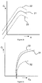
- Figure 2b illustrates a typical curve 21 of the lift coefficient of a profile vs. angle of attack.
- the angle of attack ⁇ has been illustrated in figure 2a and may be defined as the angle between a reference line on a lifting body (in this case, the chord line of an airfoil 28) and the vector 29 representing the relative motion between the blade and the air through which it is moving.
- the vector representing the relative motion between the blade and the air may be composed of two components: the wind velocity v w and the rotational velocity of the local portion of the blade v r .
- n 60 , wherein r is the radius of the local portion of the blade and n is the number of revolutions per minute.
- the angle of attack of a portion of the blade may thus be affected by the prevailing wind speed, the rotational speed of the rotor, its position along the blade span, the design twist of the airfoil and the pitch angle of the blade.
- the typical curve 21 shows that with increasing angle of attack, the lift coefficient of the profile increases, until "stall". If the angle of attack is increased further, the lift coefficient is reduced.
- a curve 22 that is substantially parallel to curve 21 may be the result: for any angle of attack, the lift coefficient is slightly higher.
- a curve 23 that is substantially parallel to curve 21 corresponds to the same profile, but with the flap in a negative position. It will be clear that in practice, the curves of the lift coefficient may be different for any profile employed on a blade.
- Figure 2c illustrates curves for the same three positions of the flap of the lift coefficient vs the drag coefficient.
- Curve 31 illustrates the profile with the flap in the neutral position
- curve 32 illustrates the profile with the flap in the positive position
- curves 33 illustrates the profile with the flap in the negative position.
- the C L - C D curve may comprise a portion in which the drag hardly increases with increasing lift.
- the curve may also comprise a portion (closer to stall) along which the drag increases more rapidly than the lift.
- the effect of the positive flap position is generally that the drag increases and the effect of a negative flap position is generally that the drag decreases.
- lift curves (C L vs ⁇ ) and drag curves may vary if a different airfoil is used.
- three-dimensional aspects may affect the lift and drag curves of a blade as well. These three-dimensional aspects are herein ignored, since the general teaching (flap towards a positive position increases the lift, and flap towards a negative position decreases the lift, representing a jump to a different lift curve) will approximately hold true for a blade as well.
- FIG. 3 illustrates some of the different flaps that may be used in embodiments of the present invention.
- Profile 15 comprises a "plain flap” illustrated in its neutral position 11, its positive position 12, and its negative position 13.
- Profile 16 illustrates a "split flap” in its neutral position, and its positive position. Such a split flap does not have a negative position.
- Profile 17 comprises a "slotted flap” in its neutral position 11, positive position 12 and negative position 13. With a slotted flap, the air may flow partially through the slot in between the flap and the remainder of the profile. Finally, profile 18 comprises a "Fowler flap” in its neutral position, its positive position 12 and its negative position 13. A peculiar property of the Fowler flap is that the chord of the profile in its neutral position is longer than in its negative position.
- movable trailing edge surfaces may be used in embodiments of the present invention.
- a Continuously Deformable Trailing Edge CDTE
- a blade may comprise one or more portions that are continuously deformable along its span.
- the influence on the curves of the lift coefficient and drag coefficient may vary.
- actuating the flap towards its positive position increases the curvature of an airfoil, which increases the lift. It further increases the drag, but to a lesser extent. As such, the loads on a blade increase, but this may be acceptable, in accordance with circumstances.
- the increase of the lift increases the aerodynamic torque of the rotor.
- Actuating a flap towards its negative position decreases the lift and may increase the drag, but generally not to the same extent.
- the extent to which the drag increases (and it may actually decrease) also depends on the angle of attack.
- the decrease in lift reduces the aerodynamic torque and the loads on the blade in general. Moving the flap to its negative position may thus be used to counteract e.g. temporary high loads on a blade.
- Figure 4 illustrates a prior art control method and shows respectively the pitch angle ( ⁇ ), rotor speed ( ⁇ rotor ), electrical power (P) and aerodynamic torque (M) at varying wind speeds.
- the pitch angle is generally not changed until nominal wind speed is reached, e.g. at 11 m/s. At a slightly lower wind speed, e.g. around 8,5 m/s, nominal rotor speed may be reached. At wind speeds above nominal wind speed, the pitch angle may be varied such as to maintain the aerodynamic torque substantially constant. The rotor speed, generator torque and electrical power generated may also be maintained substantially constant. This may be maintained from nominal wind speed to cut-out wind speed.
- the pitch mechanism is particularly suitable for adapting the wind turbine blade to a varying wind speed.
- the pitch mechanism may not be suitable to react to a sudden wind gust. Actuation of the pitch mechanism in these circumstances may be too slow.
- individual pitching may be used to compensate e.g. for wind shear, illustrated in figure 1 c.
- a blade that passes along the bottom of the swept area 4 will experience lower lift, then a blade that passes along a top portion of the swept area.
- the angle of attack of the blades may be varied along each cycle of rotation to adapt to changing wind speed.
- FIGs 5a - 5c and 5e illustrate various methods of operation in accordance with the present invention.
- the previously shown lift curves 21, 22, and 23 of a typical airfoil are shown.
- "a" the actual situation of the blade may be that the flap is in a negative position, on curve 24, but not in its most negative position.
- high loads may be predicted for a second moment in time. This may be done e.g. using a LIDAR system. Alternatively, it may be that a high load is predicted e.g. because a neighbouring wind turbine has experienced such a high load. Any other alternative method for predicting loads may also be used, such as e.g. methods involving artificial neural networks or methods involving deterministic algorithms.
- the flap In order to prepare for such a high load, the flap may be moved towards its most positive position, so that a wide range of control is available for the flap when the high load occurs. If the flap were only moved towards its most positive position, the lift of the blade would increase and the total loads as well. To counteract this phenomenon, at the same time, the blade may be pitched such that the total lift (and the total loads) remains substantially constant, point "b". It may be deduced from figure 5a that at point "b", compared to point "a”, the angle of attack is reduced and the lift is maintained substantially constant. An effect of this is that when the high load occurs, the flap may be moved quickly towards its most negative position, point "c", so as to reduce the loads. When the high load has passed, the flap may be returned towards its most positive position to regain the lift of the blade and the aerodynamic torque of the rotor.
- Figure 5b illustrates another similar method.
- a high load may be predicted for a first blade at a second moment in time
- a high load may be predicted for a second blade at a third moment in time.
- the flap of the first blade may be moved towards a more positive position in accordance with figure 5a .
- the blade may be pitched to compensate for this change.
- Figure 5c illustrates another method of operating a wind turbine.
- the blade may be in a configuration corresponding to point a.
- the flap may be in a substantially positive position. If a wind gust is predicted at this point in time, contrary to what was shown before, the flap may be moved towards its neutral position. At the same time, the blade may be pitched so as to increase the angle of attack.
- the blade When the wind gust occurs, the blade will thus be in a configuration in which it has a wider operational range to react to the wind gust.
- a Mexican hat wind gust illustrated in figure 5d
- the wind speed first decreases below the original wind speed, then quickly increases, then decreases again below the original speed, to finally stabilize again.
- the flap may thus be moved between points "c” and "d” to adapt to the varying wind speed during the wind gust.
- Figure 5e illustrates another method. In the methods illustrated so far, between the moment of predicting a load, and the moment of the load actually occurring, it was attempted to substantially maintain the lift constant.
- a constant lift means that the torque generated by the blade is substantially constant as well. The electrical power may thus be maintained at the same level as well. Depending on the particular situation however, the drag may increase, and the total loads as well.
- Criteria other than the generation of electrical power, or limit loads may be important during the operation of a wind turbine.
- a wind turbine may be in a shutdown procedure when the high load is predicted.
- the flaps or other movable surface
- the flaps may be actuated upon so that they assume a position in which their range of control to counteract the high load is increased.
- the blade(s) may be pitched such as to continue slowing down the wind turbine.
- the priority may not be to maximize the generation of electricity or the loads on the blades, but instead may be to continue reducing the speed of the wind turbine.
Landscapes
- Engineering & Computer Science (AREA)
- Physics & Mathematics (AREA)
- Fluid Mechanics (AREA)
- Life Sciences & Earth Sciences (AREA)
- Sustainable Development (AREA)
- Sustainable Energy (AREA)
- Chemical & Material Sciences (AREA)
- Combustion & Propulsion (AREA)
- Mechanical Engineering (AREA)
- General Engineering & Computer Science (AREA)
- Wind Motors (AREA)
Claims (15)
- Procédé de fonctionnement d'une éolienne comprenant une pluralité de pales (1, 2, 3), étant chacune des pales pivotantes le long de son axe longitudinal en utilisant un mécanisme de pas de pale, et comprenant chacune des pales (1, 2, 3) une ou plusieurs surfaces de flanc arrière mobiles, comprenant le procédé
dans un premier moment, prédire une charge élevée pour une ou plusieurs des pales dans un deuxième moment,
avant le deuxième moment, agir sur une ou sur plusieurs des surfaces de flanc arrière de ces pales de façon que les surfaces de flanc arrière assument une position dans laquelle elles ont une plage de contrôle plus ample pour contrecarrer les charges élevées prédites, et de façon simultanée effectuer le pas de pale de façon à ne pas altérer le fonctionnement de l'éolienne, et
dans un deuxième temps, agir sur l'une ou plusieurs surfaces de flanc arrière mobiles de l'au moins une ou des plusieurs pales afin de contrecarrer les charges élevées. - Procédé selon la revendication 1, dans lequel le pas des pales de façon à ne pas altérer le fonctionnement de l'éolienne comprend effectuer le pas des pales de façon que la génération de puissance électrique n'est pas altérée.
- Procédé selon la revendication 1 ou 2, dans lequel le pas des pales de façon à ne pas altérer le fonctionnement de l'éolienne comprend effectuer le pas des pales de façon que les charges sur les pales restent essentiellement au même niveau que dans le premier moment.
- Procédé selon l'une quelconque des revendications 1 - 3, dans lequel la prédiction d'une charge élevée pour une ou pour plusieurs pales comprend utiliser un LIDAR (51).
- Procédé selon l'une quelconque des revendications 1 - 3, dans lequel la prédiction d'une charge élevée pour une ou pour plusieurs des pales comprend mesurer les charges dans l'éolienne ou dans une autre éolienne.
- Procédé selon l'une quelconque des revendications 1 - 5, dans lequel chacune des pales comprend un ou plusieurs clapets.
- Procédé selon la revendication 6, dans lequel chacune des pales comprend une pluralité de clapets distribués le long de la longueur de la pale, et dans lequel chacun des clapets est adapté pour être actionné individuellement.
- Procédé selon l'une quelconque des revendications 1 - 7, comprenant
dans le premier moment, prédire une charge élevée pour une première pale dans le deuxième moment, et prédire une charge élevée pour une deuxième pale dans un troisième moment
avant ledit deuxième moment, agir sur une ou sur plusieurs des surfaces de flanc arrière mobiles de la première pale de façon qu'elles assument une position dans laquelle elles ont une plage de contrôle plus ample pour contrecarrer les charges élevées prédites,
avant ledit troisième moment, agir sur une ou sur plusieurs des surfaces de flanc arrière mobiles de la deuxième pale de façon qu'elles assument une position dans laquelle elles ont une plage de contrôle plus ample pour contrecarrer les charges élevées prédites,
et effectuer de façon simultanée le pas des pales de l'éolienne de façon que le fonctionnement de l'éolienne n'est pas essentiellement altéré,
dans ledit deuxième moment, agir sur une ou sur plusieurs surfaces de flanc arrière de la première pale afin de contrecarrer la charge élevée, et
dans ledit troisième moment, agir sur l'une ou sur plusieurs surfaces de flanc arrière de la deuxième pale afin de contrecarrer la charge élevée. - Procédé selon la revendication 8, dans lequel le pas des pales de l'éolienne de façon que le fonctionnement de l'éolienne n'est pas essentiellement altéré, comprend
effectuer le pas des pales de façon que la génération de puissance électrique n'est pas essentiellement altérée. - Procédé selon la revendication 8 ou 9, dans lequel le pas des pales de l'éolienne de façon que le fonctionnement de l'éolienne n'est pas essentiellement altéré comprend
effectuer le pas de la primer pale de façon que les charges sur la première pale restent essentiellement au même niveau que dans le premier moment, et
effectuer le pas de la deuxième pale de façon que les charges sur la deuxième pale restent essentiellement au même niveau que dans le premier moment. - Procédé selon l'une quelconque des revendications 1 - 10, comprenant déplacer les surfaces de flanc arrière mobiles vers une position essentiellement neutre (11).
- Procédé selon la revendication 11, comprenant en outre effectuer le pas de pale de façon à augmenter son angle d'attaque.
- Procédé selon la revendication 11, comprenant en outre effectuer le pas de pale de façon à diminuer son angle d'attaque.
- Procédé selon l'une quelconque des revendications 1 - 10, comprenant
déplacer la surface de flanc arrière mobile essentiellement vers sa position la plus négative (13), dans laquelle l'élévation de la pale est la plus petite, et
effectuer le pas de pale de façon à augmenter son angle d'attaque. - Procédé selon l'une quelconque des revendications 1 - 14, dans lequel l'éolienne comprend un système de pas de pale individuel pour chacune des pales, de façon que le pas de chacune des pales peut être effectué individuellement.
Priority Applications (3)
| Application Number | Priority Date | Filing Date | Title |
|---|---|---|---|
| EP12382077.1A EP2634419B1 (fr) | 2012-03-01 | 2012-03-01 | Procédé de fonctionnement d'une éolienne |
| PCT/EP2013/053996 WO2013127899A1 (fr) | 2012-03-01 | 2013-02-28 | Procédé de fonctionnement d'une éolienne |
| US14/377,116 US9739265B2 (en) | 2012-03-01 | 2013-02-28 | Method of operating a wind turbine |
Applications Claiming Priority (1)
| Application Number | Priority Date | Filing Date | Title |
|---|---|---|---|
| EP12382077.1A EP2634419B1 (fr) | 2012-03-01 | 2012-03-01 | Procédé de fonctionnement d'une éolienne |
Publications (2)
| Publication Number | Publication Date |
|---|---|
| EP2634419A1 EP2634419A1 (fr) | 2013-09-04 |
| EP2634419B1 true EP2634419B1 (fr) | 2016-08-24 |
Family
ID=45808392
Family Applications (1)
| Application Number | Title | Priority Date | Filing Date |
|---|---|---|---|
| EP12382077.1A Not-in-force EP2634419B1 (fr) | 2012-03-01 | 2012-03-01 | Procédé de fonctionnement d'une éolienne |
Country Status (3)
| Country | Link |
|---|---|
| US (1) | US9739265B2 (fr) |
| EP (1) | EP2634419B1 (fr) |
| WO (1) | WO2013127899A1 (fr) |
Families Citing this family (9)
| Publication number | Priority date | Publication date | Assignee | Title |
|---|---|---|---|---|
| US10250579B2 (en) * | 2013-08-13 | 2019-04-02 | Alcatel Lucent | Secure file transfers within network-based storage |
| US9689374B2 (en) * | 2013-10-09 | 2017-06-27 | Siemens Aktiengesellschaft | Method and apparatus for reduction of fatigue and gust loads on wind turbine blades |
| WO2015058209A1 (fr) | 2013-10-18 | 2015-04-23 | Tramontane Technologies, Inc. | Circuit optique amplifié |
| DK2998571T3 (en) * | 2014-09-19 | 2017-12-18 | Siemens Ag | Buoyancy actuator for a rotor blade of a wind turbine |
| DE102018100397A1 (de) * | 2018-01-10 | 2019-07-11 | Wobben Properties Gmbh | Windenergieanlage mit Endkantenströmungsklappe |
| EP3667076A1 (fr) * | 2018-12-13 | 2020-06-17 | Siemens Gamesa Renewable Energy A/S | Estimation de la vitesse du vent |
| DE102019117365A1 (de) * | 2019-06-27 | 2020-12-31 | Wobben Properties Gmbh | Rotor für eine Windenergieanlage, Windenergieanlage und zugehöriges Verfahren |
| CN113389684B (zh) * | 2021-08-18 | 2021-11-09 | 东方电气风电有限公司 | 一种风力发电机组偏航角度计数器的容错控制方法 |
| GB2617545A (en) * | 2022-03-29 | 2023-10-18 | Equinor Energy As | Reconfigurable rotor blade and method for controlling wake diffusion |
Family Cites Families (6)
| Publication number | Priority date | Publication date | Assignee | Title |
|---|---|---|---|---|
| ES2418368T3 (es) * | 2005-10-17 | 2013-08-13 | Vestas Wind Systems A/S | Pala de turbina eólica con perfil aerodinámico variable |
| ES2326203B1 (es) * | 2007-07-23 | 2010-07-09 | GAMESA INNOVATION & TECHNOLOGY, S.L. | Pala de aerogenerador con alerones arqueables. |
| EP2389510B1 (fr) * | 2009-01-22 | 2013-04-03 | Vestas Wind Systems A/S | Commande d'un rotor d'eolienne au cours d'un processus d'arret par tangage et dispositif de modification de surface |
| NL2002476C2 (en) * | 2009-02-02 | 2010-08-03 | Univ Delft Tech | WIND TURBINE. |
| EP2251543B1 (fr) * | 2009-05-14 | 2016-12-07 | ALSTOM Renewable Technologies | Procédé et système pour la prédiction de l'événement d'une rafale de vent sur une éolienne |
| US20110193344A1 (en) * | 2010-12-29 | 2011-08-11 | Vestas Wind Systems A/S | Control Network for Wind Turbine Park |
-
2012
- 2012-03-01 EP EP12382077.1A patent/EP2634419B1/fr not_active Not-in-force
-
2013
- 2013-02-28 WO PCT/EP2013/053996 patent/WO2013127899A1/fr not_active Ceased
- 2013-02-28 US US14/377,116 patent/US9739265B2/en active Active
Also Published As
| Publication number | Publication date |
|---|---|
| US20150030449A1 (en) | 2015-01-29 |
| US9739265B2 (en) | 2017-08-22 |
| WO2013127899A1 (fr) | 2013-09-06 |
| EP2634419A1 (fr) | 2013-09-04 |
Similar Documents
| Publication | Publication Date | Title |
|---|---|---|
| US9739265B2 (en) | Method of operating a wind turbine | |
| US9372201B2 (en) | Yaw and pitch angles | |
| US6726439B2 (en) | Retractable rotor blades for power generating wind and ocean current turbines and means for operating below set rotor torque limits | |
| EP2556249B1 (fr) | Éolienne | |
| EP2757252B1 (fr) | Procédé de fonctionnement d'une éolienne | |
| CN102933841B (zh) | 风力涡轮机 | |
| EP2757253B1 (fr) | Procédé de démarrage d'éolienne | |
| US7898100B2 (en) | Method of operating a wind turbine with pitch control, a wind turbine and a cluster of wind turbine | |
| EP2306003B1 (fr) | Dispositif et procédés pour le réglage d'une éolienne | |
| EP2633189B1 (fr) | Procédé de commande d'une éolienne | |
| US20190264653A1 (en) | Methods of Operating a Wind Turbine | |
| CN102203412A (zh) | 风力发电装置及风力发电装置的偏航回转控制方法 | |
| WO2011157271A2 (fr) | Procédé et unité de commande pour commander une éolienne en fonction d'une charge subie par l'éolienne | |
| EP2818695A1 (fr) | Procédé pour commander des charges dans une éolienne | |
| EP2840256A1 (fr) | Pale de turbine éolienne | |
| EP2848805A1 (fr) | Procédé de fonctionnement d'une éolienne | |
| EP3020959B1 (fr) | Procédé de fonctionnement d'une éolienne et éoliennes | |
| EP2818698B1 (fr) | Procédé de fonctionnement d'une éolienne | |
| EP2927483A1 (fr) | Régulation du bruit dans des éoliennes | |
| CN103174589A (zh) | 用于控制风力涡轮机的方法 | |
| EP2848803B1 (fr) | Pale d'éolienne et méthode de contrôle pour la portée de la pale | |
| Lackner | Wind Turbine Control Systems: Current Status and Future Developments |
Legal Events
| Date | Code | Title | Description |
|---|---|---|---|
| PUAI | Public reference made under article 153(3) epc to a published international application that has entered the european phase |
Free format text: ORIGINAL CODE: 0009012 |
|
| AK | Designated contracting states |
Kind code of ref document: A1 Designated state(s): AL AT BE BG CH CY CZ DE DK EE ES FI FR GB GR HR HU IE IS IT LI LT LU LV MC MK MT NL NO PL PT RO RS SE SI SK SM TR |
|
| AX | Request for extension of the european patent |
Extension state: BA ME |
|
| 17P | Request for examination filed |
Effective date: 20140304 |
|
| RBV | Designated contracting states (corrected) |
Designated state(s): AL AT BE BG CH CY CZ DE DK EE ES FI FR GB GR HR HU IE IS IT LI LT LU LV MC MK MT NL NO PL PT RO RS SE SI SK SM TR |
|
| GRAP | Despatch of communication of intention to grant a patent |
Free format text: ORIGINAL CODE: EPIDOSNIGR1 |
|
| INTG | Intention to grant announced |
Effective date: 20150824 |
|
| GRAS | Grant fee paid |
Free format text: ORIGINAL CODE: EPIDOSNIGR3 |
|
| GRAA | (expected) grant |
Free format text: ORIGINAL CODE: 0009210 |
|
| AK | Designated contracting states |
Kind code of ref document: B1 Designated state(s): AL AT BE BG CH CY CZ DE DK EE ES FI FR GB GR HR HU IE IS IT LI LT LU LV MC MK MT NL NO PL PT RO RS SE SI SK SM TR |
|
| REG | Reference to a national code |
Ref country code: GB Ref legal event code: FG4D |
|
| REG | Reference to a national code |
Ref country code: CH Ref legal event code: EP |
|
| REG | Reference to a national code |
Ref country code: AT Ref legal event code: REF Ref document number: 823349 Country of ref document: AT Kind code of ref document: T Effective date: 20160915 |
|
| REG | Reference to a national code |
Ref country code: IE Ref legal event code: FG4D |
|
| RAP2 | Party data changed (patent owner data changed or rights of a patent transferred) |
Owner name: ALSTOM RENEWABLE TECHNOLOGIES |
|
| REG | Reference to a national code |
Ref country code: DE Ref legal event code: R096 Ref document number: 602012022139 Country of ref document: DE |
|
| REG | Reference to a national code |
Ref country code: LT Ref legal event code: MG4D |
|
| REG | Reference to a national code |
Ref country code: NL Ref legal event code: MP Effective date: 20160824 |
|
| REG | Reference to a national code |
Ref country code: AT Ref legal event code: MK05 Ref document number: 823349 Country of ref document: AT Kind code of ref document: T Effective date: 20160824 |
|
| PG25 | Lapsed in a contracting state [announced via postgrant information from national office to epo] |
Ref country code: NL Free format text: LAPSE BECAUSE OF FAILURE TO SUBMIT A TRANSLATION OF THE DESCRIPTION OR TO PAY THE FEE WITHIN THE PRESCRIBED TIME-LIMIT Effective date: 20160824 Ref country code: RS Free format text: LAPSE BECAUSE OF FAILURE TO SUBMIT A TRANSLATION OF THE DESCRIPTION OR TO PAY THE FEE WITHIN THE PRESCRIBED TIME-LIMIT Effective date: 20160824 Ref country code: IT Free format text: LAPSE BECAUSE OF FAILURE TO SUBMIT A TRANSLATION OF THE DESCRIPTION OR TO PAY THE FEE WITHIN THE PRESCRIBED TIME-LIMIT Effective date: 20160824 Ref country code: LT Free format text: LAPSE BECAUSE OF FAILURE TO SUBMIT A TRANSLATION OF THE DESCRIPTION OR TO PAY THE FEE WITHIN THE PRESCRIBED TIME-LIMIT Effective date: 20160824 Ref country code: HR Free format text: LAPSE BECAUSE OF FAILURE TO SUBMIT A TRANSLATION OF THE DESCRIPTION OR TO PAY THE FEE WITHIN THE PRESCRIBED TIME-LIMIT Effective date: 20160824 Ref country code: FI Free format text: LAPSE BECAUSE OF FAILURE TO SUBMIT A TRANSLATION OF THE DESCRIPTION OR TO PAY THE FEE WITHIN THE PRESCRIBED TIME-LIMIT Effective date: 20160824 Ref country code: NO Free format text: LAPSE BECAUSE OF FAILURE TO SUBMIT A TRANSLATION OF THE DESCRIPTION OR TO PAY THE FEE WITHIN THE PRESCRIBED TIME-LIMIT Effective date: 20161124 |
|
| PG25 | Lapsed in a contracting state [announced via postgrant information from national office to epo] |
Ref country code: PT Free format text: LAPSE BECAUSE OF FAILURE TO SUBMIT A TRANSLATION OF THE DESCRIPTION OR TO PAY THE FEE WITHIN THE PRESCRIBED TIME-LIMIT Effective date: 20161226 Ref country code: LV Free format text: LAPSE BECAUSE OF FAILURE TO SUBMIT A TRANSLATION OF THE DESCRIPTION OR TO PAY THE FEE WITHIN THE PRESCRIBED TIME-LIMIT Effective date: 20160824 Ref country code: ES Free format text: LAPSE BECAUSE OF FAILURE TO SUBMIT A TRANSLATION OF THE DESCRIPTION OR TO PAY THE FEE WITHIN THE PRESCRIBED TIME-LIMIT Effective date: 20160824 Ref country code: GR Free format text: LAPSE BECAUSE OF FAILURE TO SUBMIT A TRANSLATION OF THE DESCRIPTION OR TO PAY THE FEE WITHIN THE PRESCRIBED TIME-LIMIT Effective date: 20161125 Ref country code: AT Free format text: LAPSE BECAUSE OF FAILURE TO SUBMIT A TRANSLATION OF THE DESCRIPTION OR TO PAY THE FEE WITHIN THE PRESCRIBED TIME-LIMIT Effective date: 20160824 Ref country code: SE Free format text: LAPSE BECAUSE OF FAILURE TO SUBMIT A TRANSLATION OF THE DESCRIPTION OR TO PAY THE FEE WITHIN THE PRESCRIBED TIME-LIMIT Effective date: 20160824 |
|
| PG25 | Lapsed in a contracting state [announced via postgrant information from national office to epo] |
Ref country code: EE Free format text: LAPSE BECAUSE OF FAILURE TO SUBMIT A TRANSLATION OF THE DESCRIPTION OR TO PAY THE FEE WITHIN THE PRESCRIBED TIME-LIMIT Effective date: 20160824 Ref country code: RO Free format text: LAPSE BECAUSE OF FAILURE TO SUBMIT A TRANSLATION OF THE DESCRIPTION OR TO PAY THE FEE WITHIN THE PRESCRIBED TIME-LIMIT Effective date: 20160824 |
|
| REG | Reference to a national code |
Ref country code: DE Ref legal event code: R097 Ref document number: 602012022139 Country of ref document: DE |
|
| PG25 | Lapsed in a contracting state [announced via postgrant information from national office to epo] |
Ref country code: SM Free format text: LAPSE BECAUSE OF FAILURE TO SUBMIT A TRANSLATION OF THE DESCRIPTION OR TO PAY THE FEE WITHIN THE PRESCRIBED TIME-LIMIT Effective date: 20160824 Ref country code: CZ Free format text: LAPSE BECAUSE OF FAILURE TO SUBMIT A TRANSLATION OF THE DESCRIPTION OR TO PAY THE FEE WITHIN THE PRESCRIBED TIME-LIMIT Effective date: 20160824 Ref country code: BG Free format text: LAPSE BECAUSE OF FAILURE TO SUBMIT A TRANSLATION OF THE DESCRIPTION OR TO PAY THE FEE WITHIN THE PRESCRIBED TIME-LIMIT Effective date: 20161124 Ref country code: PL Free format text: LAPSE BECAUSE OF FAILURE TO SUBMIT A TRANSLATION OF THE DESCRIPTION OR TO PAY THE FEE WITHIN THE PRESCRIBED TIME-LIMIT Effective date: 20160824 Ref country code: SK Free format text: LAPSE BECAUSE OF FAILURE TO SUBMIT A TRANSLATION OF THE DESCRIPTION OR TO PAY THE FEE WITHIN THE PRESCRIBED TIME-LIMIT Effective date: 20160824 Ref country code: BE Free format text: LAPSE BECAUSE OF FAILURE TO SUBMIT A TRANSLATION OF THE DESCRIPTION OR TO PAY THE FEE WITHIN THE PRESCRIBED TIME-LIMIT Effective date: 20160824 Ref country code: DK Free format text: LAPSE BECAUSE OF FAILURE TO SUBMIT A TRANSLATION OF THE DESCRIPTION OR TO PAY THE FEE WITHIN THE PRESCRIBED TIME-LIMIT Effective date: 20160824 |
|
| PLBE | No opposition filed within time limit |
Free format text: ORIGINAL CODE: 0009261 |
|
| STAA | Information on the status of an ep patent application or granted ep patent |
Free format text: STATUS: NO OPPOSITION FILED WITHIN TIME LIMIT |
|
| 26N | No opposition filed |
Effective date: 20170526 |
|
| PG25 | Lapsed in a contracting state [announced via postgrant information from national office to epo] |
Ref country code: SI Free format text: LAPSE BECAUSE OF FAILURE TO SUBMIT A TRANSLATION OF THE DESCRIPTION OR TO PAY THE FEE WITHIN THE PRESCRIBED TIME-LIMIT Effective date: 20160824 |
|
| REG | Reference to a national code |
Ref country code: DE Ref legal event code: R119 Ref document number: 602012022139 Country of ref document: DE |
|
| REG | Reference to a national code |
Ref country code: CH Ref legal event code: PL |
|
| GBPC | Gb: european patent ceased through non-payment of renewal fee |
Effective date: 20170301 |
|
| PG25 | Lapsed in a contracting state [announced via postgrant information from national office to epo] |
Ref country code: MC Free format text: LAPSE BECAUSE OF FAILURE TO SUBMIT A TRANSLATION OF THE DESCRIPTION OR TO PAY THE FEE WITHIN THE PRESCRIBED TIME-LIMIT Effective date: 20160824 |
|
| REG | Reference to a national code |
Ref country code: IE Ref legal event code: MM4A |
|
| REG | Reference to a national code |
Ref country code: FR Ref legal event code: ST Effective date: 20171130 |
|
| PG25 | Lapsed in a contracting state [announced via postgrant information from national office to epo] |
Ref country code: FR Free format text: LAPSE BECAUSE OF NON-PAYMENT OF DUE FEES Effective date: 20170331 Ref country code: LU Free format text: LAPSE BECAUSE OF NON-PAYMENT OF DUE FEES Effective date: 20170301 Ref country code: DE Free format text: LAPSE BECAUSE OF NON-PAYMENT OF DUE FEES Effective date: 20171003 |
|
| PG25 | Lapsed in a contracting state [announced via postgrant information from national office to epo] |
Ref country code: IE Free format text: LAPSE BECAUSE OF NON-PAYMENT OF DUE FEES Effective date: 20170301 Ref country code: CH Free format text: LAPSE BECAUSE OF NON-PAYMENT OF DUE FEES Effective date: 20170331 Ref country code: GB Free format text: LAPSE BECAUSE OF NON-PAYMENT OF DUE FEES Effective date: 20170301 Ref country code: LI Free format text: LAPSE BECAUSE OF NON-PAYMENT OF DUE FEES Effective date: 20170331 |
|
| PG25 | Lapsed in a contracting state [announced via postgrant information from national office to epo] |
Ref country code: MT Free format text: LAPSE BECAUSE OF NON-PAYMENT OF DUE FEES Effective date: 20170301 |
|
| PG25 | Lapsed in a contracting state [announced via postgrant information from national office to epo] |
Ref country code: AL Free format text: LAPSE BECAUSE OF FAILURE TO SUBMIT A TRANSLATION OF THE DESCRIPTION OR TO PAY THE FEE WITHIN THE PRESCRIBED TIME-LIMIT Effective date: 20160824 |
|
| PG25 | Lapsed in a contracting state [announced via postgrant information from national office to epo] |
Ref country code: HU Free format text: LAPSE BECAUSE OF FAILURE TO SUBMIT A TRANSLATION OF THE DESCRIPTION OR TO PAY THE FEE WITHIN THE PRESCRIBED TIME-LIMIT; INVALID AB INITIO Effective date: 20120301 |
|
| PG25 | Lapsed in a contracting state [announced via postgrant information from national office to epo] |
Ref country code: CY Free format text: LAPSE BECAUSE OF NON-PAYMENT OF DUE FEES Effective date: 20160824 |
|
| PG25 | Lapsed in a contracting state [announced via postgrant information from national office to epo] |
Ref country code: MK Free format text: LAPSE BECAUSE OF FAILURE TO SUBMIT A TRANSLATION OF THE DESCRIPTION OR TO PAY THE FEE WITHIN THE PRESCRIBED TIME-LIMIT Effective date: 20160824 |
|
| PG25 | Lapsed in a contracting state [announced via postgrant information from national office to epo] |
Ref country code: TR Free format text: LAPSE BECAUSE OF FAILURE TO SUBMIT A TRANSLATION OF THE DESCRIPTION OR TO PAY THE FEE WITHIN THE PRESCRIBED TIME-LIMIT Effective date: 20160824 |
|
| PG25 | Lapsed in a contracting state [announced via postgrant information from national office to epo] |
Ref country code: IS Free format text: LAPSE BECAUSE OF FAILURE TO SUBMIT A TRANSLATION OF THE DESCRIPTION OR TO PAY THE FEE WITHIN THE PRESCRIBED TIME-LIMIT Effective date: 20161224 |