EP2634423A2 - Eolienne de type à vent arrière - Google Patents
Eolienne de type à vent arrière Download PDFInfo
- Publication number
- EP2634423A2 EP2634423A2 EP13157353.7A EP13157353A EP2634423A2 EP 2634423 A2 EP2634423 A2 EP 2634423A2 EP 13157353 A EP13157353 A EP 13157353A EP 2634423 A2 EP2634423 A2 EP 2634423A2
- Authority
- EP
- European Patent Office
- Prior art keywords
- rotor
- nacelle
- heat exchanger
- power generation
- downwind
- Prior art date
- Legal status (The legal status is an assumption and is not a legal conclusion. Google has not performed a legal analysis and makes no representation as to the accuracy of the status listed.)
- Withdrawn
Links
- 238000010248 power generation Methods 0.000 title claims abstract description 49
- 230000002093 peripheral effect Effects 0.000 claims description 4
- 238000001816 cooling Methods 0.000 abstract description 33
- 230000005611 electricity Effects 0.000 description 14
- 238000009434 installation Methods 0.000 description 9
- 239000003507 refrigerant Substances 0.000 description 7
- 230000002238 attenuated effect Effects 0.000 description 5
- 230000007423 decrease Effects 0.000 description 5
- 238000000034 method Methods 0.000 description 5
- 230000008901 benefit Effects 0.000 description 3
- 230000006866 deterioration Effects 0.000 description 3
- 238000010586 diagram Methods 0.000 description 2
- 230000000694 effects Effects 0.000 description 2
- 230000006872 improvement Effects 0.000 description 2
- 230000008569 process Effects 0.000 description 2
- 230000008859 change Effects 0.000 description 1
- 239000003638 chemical reducing agent Substances 0.000 description 1
- 239000000470 constituent Substances 0.000 description 1
- 230000005484 gravity Effects 0.000 description 1
- 230000020169 heat generation Effects 0.000 description 1
- 239000007788 liquid Substances 0.000 description 1
- 238000012423 maintenance Methods 0.000 description 1
- 238000004519 manufacturing process Methods 0.000 description 1
- 239000000463 material Substances 0.000 description 1
- 238000005259 measurement Methods 0.000 description 1
- 230000007246 mechanism Effects 0.000 description 1
- 230000009467 reduction Effects 0.000 description 1
- 238000003756 stirring Methods 0.000 description 1
Images



Classifications
-
- F—MECHANICAL ENGINEERING; LIGHTING; HEATING; WEAPONS; BLASTING
- F03—MACHINES OR ENGINES FOR LIQUIDS; WIND, SPRING, OR WEIGHT MOTORS; PRODUCING MECHANICAL POWER OR A REACTIVE PROPULSIVE THRUST, NOT OTHERWISE PROVIDED FOR
- F03D—WIND MOTORS
- F03D80/00—Details, components or accessories not provided for in groups F03D1/00 - F03D17/00
- F03D80/80—Arrangement of components within nacelles or towers
-
- F—MECHANICAL ENGINEERING; LIGHTING; HEATING; WEAPONS; BLASTING
- F03—MACHINES OR ENGINES FOR LIQUIDS; WIND, SPRING, OR WEIGHT MOTORS; PRODUCING MECHANICAL POWER OR A REACTIVE PROPULSIVE THRUST, NOT OTHERWISE PROVIDED FOR
- F03D—WIND MOTORS
- F03D80/00—Details, components or accessories not provided for in groups F03D1/00 - F03D17/00
- F03D80/60—Cooling or heating of wind motors
-
- F—MECHANICAL ENGINEERING; LIGHTING; HEATING; WEAPONS; BLASTING
- F03—MACHINES OR ENGINES FOR LIQUIDS; WIND, SPRING, OR WEIGHT MOTORS; PRODUCING MECHANICAL POWER OR A REACTIVE PROPULSIVE THRUST, NOT OTHERWISE PROVIDED FOR
- F03D—WIND MOTORS
- F03D9/00—Adaptations of wind motors for special use; Combinations of wind motors with apparatus driven thereby; Wind motors specially adapted for installation in particular locations
- F03D9/20—Wind motors characterised by the driven apparatus
- F03D9/25—Wind motors characterised by the driven apparatus the apparatus being an electrical generator
-
- F—MECHANICAL ENGINEERING; LIGHTING; HEATING; WEAPONS; BLASTING
- F03—MACHINES OR ENGINES FOR LIQUIDS; WIND, SPRING, OR WEIGHT MOTORS; PRODUCING MECHANICAL POWER OR A REACTIVE PROPULSIVE THRUST, NOT OTHERWISE PROVIDED FOR
- F03D—WIND MOTORS
- F03D15/00—Transmission of mechanical power
- F03D15/10—Transmission of mechanical power using gearing not limited to rotary motion, e.g. with oscillating or reciprocating members
-
- F—MECHANICAL ENGINEERING; LIGHTING; HEATING; WEAPONS; BLASTING
- F05—INDEXING SCHEMES RELATING TO ENGINES OR PUMPS IN VARIOUS SUBCLASSES OF CLASSES F01-F04
- F05B—INDEXING SCHEME RELATING TO WIND, SPRING, WEIGHT, INERTIA OR LIKE MOTORS, TO MACHINES OR ENGINES FOR LIQUIDS COVERED BY SUBCLASSES F03B, F03D AND F03G
- F05B2240/00—Components
- F05B2240/10—Stators
- F05B2240/14—Casings, housings, nacelles, gondels or the like, protecting or supporting assemblies there within
-
- F—MECHANICAL ENGINEERING; LIGHTING; HEATING; WEAPONS; BLASTING
- F05—INDEXING SCHEMES RELATING TO ENGINES OR PUMPS IN VARIOUS SUBCLASSES OF CLASSES F01-F04
- F05B—INDEXING SCHEME RELATING TO WIND, SPRING, WEIGHT, INERTIA OR LIKE MOTORS, TO MACHINES OR ENGINES FOR LIQUIDS COVERED BY SUBCLASSES F03B, F03D AND F03G
- F05B2240/00—Components
- F05B2240/20—Rotors
- F05B2240/21—Rotors for wind turbines
- F05B2240/221—Rotors for wind turbines with horizontal axis
- F05B2240/2213—Rotors for wind turbines with horizontal axis and with the rotor downwind from the yaw pivot axis
-
- F—MECHANICAL ENGINEERING; LIGHTING; HEATING; WEAPONS; BLASTING
- F05—INDEXING SCHEMES RELATING TO ENGINES OR PUMPS IN VARIOUS SUBCLASSES OF CLASSES F01-F04
- F05B—INDEXING SCHEME RELATING TO WIND, SPRING, WEIGHT, INERTIA OR LIKE MOTORS, TO MACHINES OR ENGINES FOR LIQUIDS COVERED BY SUBCLASSES F03B, F03D AND F03G
- F05B2260/00—Function
- F05B2260/20—Heat transfer, e.g. cooling
- F05B2260/201—Heat transfer, e.g. cooling by impingement of a fluid
-
- Y—GENERAL TAGGING OF NEW TECHNOLOGICAL DEVELOPMENTS; GENERAL TAGGING OF CROSS-SECTIONAL TECHNOLOGIES SPANNING OVER SEVERAL SECTIONS OF THE IPC; TECHNICAL SUBJECTS COVERED BY FORMER USPC CROSS-REFERENCE ART COLLECTIONS [XRACs] AND DIGESTS
- Y02—TECHNOLOGIES OR APPLICATIONS FOR MITIGATION OR ADAPTATION AGAINST CLIMATE CHANGE
- Y02E—REDUCTION OF GREENHOUSE GAS [GHG] EMISSIONS, RELATED TO ENERGY GENERATION, TRANSMISSION OR DISTRIBUTION
- Y02E10/00—Energy generation through renewable energy sources
- Y02E10/70—Wind energy
- Y02E10/72—Wind turbines with rotation axis in wind direction
Definitions
- the present invention relates to downwind rotor type wind power generation devices in which a rotor is positioned downwind of a nacelle.
- wind power generation devices which use wind as an inexhaustible source of energy available in nature and convert the wind energy into electric energy.
- a wind power generation device is a relatively large structure and the site where it can be installed is limited, so the amount of electricity generated per device is expected to increase so that a smaller number of devices generate as much electricity as desired.
- its generator and step-up gear In order for a single wind power generation device to generate a larger amount of electricity, its generator and step-up gear must be larger and the heat generated by the generator and step-up gear (energy loss) will increase, so it is necessary to increase the capacity of its cooling unit.
- a technique which uses a fan to send air from the rear portion of a nacelle housing a generator and a step-up gear to its front portion to cool the inside of the nacelle is disclosed (for example, JP-A-2010-116925 (PTL 1)) and also a technique which uses cooling fans located in upper and rear portions of a nacelle is disclosed (for example, JP-A-2008-286115 (PTL 2)).
- the above wind power generation devices described in PTL 1 to 3 are so-called upwind rotor type wind power generation devices in which a rotor is positioned upwind of a nacelle fixed on a tower.
- the heat exchanger in order to expose the heat exchanger to the external air, the heat exchanger must protrude outward from the periphery of the nacelle.
- a nacelle with a heat exchanger protruding like this is not permitted to be transported from the factory to the installation site. Therefore, it is necessary to remove the heat exchanger before transportation and attach it again at the installation site, resulting in increased transportation and installation costs.
- the heat exchanger can turn so that at the time of transportation and installation it is retracted from the periphery of the nacelle so as not to protrude from the nacelle.
- this retraction structure requires a large-scale mechanism, which is a contributory factor for a rise in manufacturing cost and a decline in the freedom of nacelle design.
- upwind rotor wind type power generation devices have a problem that since the heat exchanger must be located backward of the rotor, the rotor reduces the wind energy and the generator and step-up gear cannot be cooled sufficiently.
- the present invention has been made in view of the above problem and has an object to provide a downwind rotor type wind power generation device which allows a nacelle to be transported and installed more conveniently without the need for troublesome detachment and reattachment of a heat exchanger and improves the efficiency in cooling a generator.
- a downwind rotor type wind power generation device which includes a rotor having a hub and a plurality of blades extending radially from the hub, a nacelle having a generator for converting the rotational energy of the rotor into electric energy and a heat exchanger for exchanging heat with heat generated at least by the generator and supporting the rotor rotatably, and a tower supporting the nacelle rotatably around a vertical axis so that the rotor is positioned downwind.
- the heat exchanger is located on the opposite side of the rotor with respect to the vertical axis in the nacelle so as to be exposed.
- external dimensions of the heat exchanger may be within peripheral dimensions of the nacelle.
- the downwind rotor type wind power generation device may further include a front cover located on the opposite side of the rotor with respect to the vertical axis and over the heat exchanger to prevent light from entering the heat exchanger from above.
- the downwind rotor type wind power generation device may further include a side cover which is located on the opposite side of the rotor with respect to the heat exchanger and extends in the axial direction of the rotor.
- the downwind rotor type wind power generation device may further include a lifting device which is located over the heat exchanger and can lift and lower the heat exchanger.
- the nacelle can be transported and installed more conveniently without the need for troublesome detachment and reattachment of the heat exchanger and the efficiency in cooling the generator can be improved.
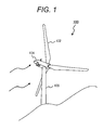
- Fig. 1 is an external view showing an appearance of a downwind rotor type wind power generation device 100 and Fig. 2 is a functional block diagram illustrating the general functionality of the downwind rotor type wind power generation device 100.
- the terms “frontward” and “backward” are sometimes used in the explanation of positional relationship of components of the downwind rotor type wind power generation device 100. Since the downwind rotor type wind power generation device 100 is so designed that its tip portion is oriented upwind, it may be thought that "frontward” corresponds to upwind and “backward” corresponds to downwind.
- the downwind rotor type wind power generation device 100 includes a rotor 102, a nacelle 104, and a tower 106.
- the rotor 102 includes a hub 112, a plurality of blades 114 extending radially from the hub 112, and a rotor shaft 116 coupled to the hub 112, extending perpendicularly to a plane formed by the blades 114. As the wind hits the blades 114, due to its lift force the rotor 102 rotates around the rotor shaft 116.
- the nacelle 104 includes a nacelle frame 120, a step-up gear 122, a generator 124, and a control board 126.
- the nacelle frame 120 includes a platform or structure to bear the weight load on the nacelle 104.
- the step-up gear 122 and the generator 124 are supported by the platform or structure of the nacelle frame 120.
- the step-up gear 122 is pivotally supports the rotor shaft 116 and increases the rotation speed of the rotor shaft 116 to rotate another rotating shaft 122a.
- the step-up gear 122 and nacelle frame 120 rotatably support the rotor 102 in this way.
- the generator 124 is coupled to the rotating shaft 122a whose speed is increased by the step-up gear 122, so that the rotational energy of the rotor 102 is converted into electric energy.
- the control board 126 performs pitch control of the rotor 102 and electric power control of the generator 124.
- refrigerant gas or liquid
- a circulating pump 132 is pressurized by a circulating pump 132 and introduced into the generator 124 and step-up gear 122 to collect the heat generated by the generator 124 and step-up gear 122 before being conveyed to a heat exchanger 134 such as a radiator.
- a heat exchanger 134 heat exchange between the hot refrigerant and the external air takes place and the refrigerant cooled by heat exchange is returned to the circulating pump 132. This circulation of refrigerant cools the generator 124 and step-up gear 122.
- the cooling unit 130 includes an impeller 136, a step-up gear 138, and a cooling fan 140.
- the impeller 136 is rotatably supported by the nacelle 104.
- the step-up gear 138 increases the rotation speed of the impeller 136 to rotate another rotating shaft and directly drives the circulating pump 132 (gives pressure directly to the refrigerant by rotational energy).
- the cooling fan 140 is fixed on the rotating shaft of the impeller 136 or step-up gear 138 and rotates in a way to follow the rotation of the impeller 136 to stir the air inside the nacelle 104 and homogenize the atmospheric temperature in the nacelle 104.
- the cooling unit 130 will be described in more detail later.
- a vane anemometer 152 which measures the direction and speed of the wind received by the downwind rotor type wind power generation device 100 is provided on a nacelle cover 150 which serves as an exterior of the nacelle 104.
- the tower 106 is coupled virtually to the center of gravity of the rotor 102 and nacelle 104 and supports the nacelle 104 rotatably around a vertical axis 160.
- the rotor 102 is coupled to the nacelle 104 and as the blades 114 of the rotor 102 receive the wind, the nacelle 104 turns so that the rotor 102 is positioned downwind of the tower 106.
- the wind energy is utilized to make the virtual plane formed by the blades 114 of the rotor 102 perpendicular to the direction in which the wind flows so that the wind energy can be captured efficiently.
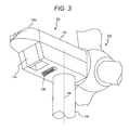
- Fig. 3 is a perspective view of the nacelle 104 as seen from below.
- the heat exchanger 134 is located on the opposite side of the rotor 102 (front portion of the nacelle 104) with respect to the vertical axis 160 and in a lower portion of the nacelle 104 and exposed to the external air.
- the heat exchanger 134 is inclined so that a lower portion thereof has a shorter distance from the vertical axis 160.
- the way the heat exchanger 134 is positioned in relation to the nacelle 104 is not limited thereto and it may be positioned vertically upright or in other various ways.
- the external dimensions of the nacelle 104 should be large enough.
- the size limit for transportation under the road traffic law for example, 4.5 m in height x 4.5 m in width
- the size limit would be exceeded by a protruding body attached to the periphery to the nacelle 104. In that case, it is necessary to once detach the heat exchanger as a protruding body from the nacelle after operation check of the nacelle and reattach it at the installation site of the wind power generation device.
- the heat exchanger 134 since the heat exchanger 134 is required to exchange heat with the external air directly, it must be exposed to the external air outside the nacelle 104, but if it is simply reattached to the periphery of the nacelle 104, transportation and installation costs would rise. In addition, its reattachment at the installation site might cause quality deterioration.
- the heat exchanger 134 is located on the upwind side tip of the nacelle 104, taking advantage of the special feature of the downwind rotor type wind power generation device 100 that the rotor 102 is located on the downwind side.
- the heat exchanger 134 is located on the upwind side tip of the nacelle 104 in this way, the external dimensions of the heat exchanger 134 is within the peripheral dimensions of the nacelle 104 and the dimensions (width and height) of the periphery of the nacelle 104 (in the circumferential direction of the rotor shaft 116) remain unchanged regardless of whether or not the heat exchanger 134 is attached.
- the peripheral dimensions of the nacelle 104 are kept within the legal size limit even when the heat exchanger 134 is not detached. Therefore, the nacelle 104 can be transported with the heat exchanger 134 attached thereto and there is no need for detachment and reattachment of the heat exchanger 134 at the time of transportation and installation. This resolves the problems of increased installation cost and quality deterioration.
- the heat exchanger in an upwind rotor type wind power generation device, even if a heat exchanger is used, the heat exchanger must be positioned downwind of the rotor and due to interference by the rotor, it can only receive, for example, about 50% of the wind energy received by the rotor, so it cannot provide sufficient cooling efficiency.
- the heat exchanger 134 receives the wind energy on the most upwind side of the nacelle 104, so the wind energy is not attenuated and a higher cooling efficiency is achieved.
- the heat exchanger 134 exposed from the nacelle 104, passively receives the external air and does not require a means to take in the external air forcedly, such as a fan, thereby contributing to cost reduction, decrease in the number of components, and improvement in design freedom.
- the rotor 102 is positioned downwind of the heat exchanger 134.
- the heat exchanger 134 does not protrude from the periphery of the nacelle 104 and the wind energy which the rotor 102 receives is not attenuated. Even if the wind energy is attenuated by the heat exchanger 134, the point at which the wind force is applied is outside the rotation of the blades 114, so the amount of wind energy in the rotation center scarcely affects the amount of electricity generated. For this reason, there is no problem with the structure in which the rotor 102 is positioned downwind of the heat exchanger 134.
- the heat exchanger In an upwind rotor type wind power generation device, the heat exchanger must be located over the nacelle and in a fine weather it is easily affected by the sunlight and due to the sunlight heat it cannot provide sufficient cooling efficiency.
- a front cover 150a as a constituent part of the nacelle cover 150 is located in a forward position of the nacelle 104 (on the opposite side of the rotor 102 with respect to the vertical axis 160) and over the heat exchanger 134 to prevent the sunlight from entering the heat exchanger 134 from above. Therefore, the heat exchanger 134 can efficiently receive the wind from forward of the nacelle 104 and provide a higher cooling efficiency while avoiding the influence of the sunlight from above.
- a vane anemometer is provided to ensure that electricity is stably generated with high efficiency.
- the vane anemometer be located on the periphery of the nacelle 104 and over the nacelle 104.
- the heat exchanger 134 might make the wind flow over the nacelle 104 turbulent at the tip portion of the nacelle 104.
- the front cover 150a has a curved surface whose curvature radius changes gradually, so that the wind from forward is rectified and disturbance in the direction and speed of the wind over the tip portion of the nacelle 104 is minimized.
- the vane anemometer 152 can ensure high accuracy in measurement.
- Fig. 4 is a perspective view of the nacelle 104 as seen from below and Figs. 5A and 5B are bottom views illustrating how side covers 150b work.
- the side covers 150b extending in the direction of the rotor shaft 116 may be provided in a lower part of the tip portion of the nacelle 104 (on the opposite side of the rotor with respect to the heat exchanger 134) and upwind of the heat exchanger 134.
- Each of these side covers 150b is fixed on the nacelle 104 or attached rotatably around a vertically extending rotation axis 150c to regulate the air volume.
- the side covers 150b are turned around the rotation axes 150c as shown in Fig. 5A so as to decrease the area of the upwind side opening and produce a reducer effect to decrease the speed of the wind received by the heat exchanger 134 and alleviate the wind load on the heat exchanger 134 in the strong wind.
- the side covers 150b are turned around the rotation axes 150c as shown in Fig. 5B to increase the area of the upwind side opening so that the wind forward of the nacelle 104 is collected as indicated by arrows in Fig. 5B and the introduced air is led into the heat exchanger 134 without leakage. Therefore, even in a weak wind, the heat exchanger 134 can provide a higher cooling efficiency.
- Fig. 6 illustrates the location and position of the heat exchanger 134.
- the nacelle frame 120 is located inside the nacelle 104.
- the heat exchanger 134 is fixed on the nacelle frame 120 directly or indirectly through a bracket or the like so that the heat exchanger 134 is supported firmly.
- the heat exchanger 134 is connected to various circuits of the cooling unit 130 such as the circulating pump 132 through joints and can be detached for maintenance or replacement of the heat exchanger 134.
- a lifting device 170 which can lift and lower the heat exchanger 134 while supporting it in a tensioned state is provided over the heat exchanger 134 inside the nacelle 104, so that the heat exchanger 134 can be vertically lifted or lowered directly without being moved horizontally from the tip portion of the nacelle 104.
- the circulating pump 132 circulates the refrigerant between the generator 124 and step-up gear 122 and the heat exchanger 134.
- a large amount of electricity is required to drive the circulating pump 132.
- electricity is not supplied to the circulating pump 132 and instead the circulating pump 132 is driven directly by the torque of the impeller 136.
- the impeller 136 is located at a lower part of the tip portion of the nacelle 104 and downwind of the heat exchanger 134 as shown in Fig. 3 .
- the impeller 136 is located at the tip portion of the nacelle 104 so that it can directly receive the wind energy not attenuated and thus the circulation efficiency of the circulating pump 132 (coolingefficiency of the coolingunit 130) canbe improved.
- the impeller 136 can be supported rotatably without the need for a special fixing member. This means that the nacelle 104 can be constructed at low cost and light in weight. It may be possible that the impeller 136 is located not at the lower portion of the nacelle 104 but at a lateral side of it, but if that is the case, depending on the orientation (rotation angle) of the nacelle 104, the lateral side of the nacelle 104 would become an obstacle and the air volume (force of wind) which the impeller 136 receives would vary.
- the impeller 136 is located at a upper portion of the nacelle 104, it might make the wind flow over the nacelle 104 turbulent, resulting in deterioration in the measuring accuracy of the vane anemometer 152. If the impeller 136 is located downwind of the vane anemometer 152, the wind energy would be attenuated by interference by the vane anemometer 152 and sufficient cooling efficiency might not be achieved. Therefore, it is desirable that the impeller 136 be located at a lower portion of the nacelle 104.
- Fig. 7 is a graph which explains the rotation speed of the impeller 136.
- This embodiment uses a drag type impeller 136. It is known that when the drag type impeller 136 is used, the rotation speed 210 relative to the wind energy is somewhat higher than the rotation speed 212 of a lift type impeller while the wind energy is small. This means that even when the wind is weak, the circulating pump 132 can be driven and a desired cooling capacity can be obtained.
- the cooling efficiency varies according to the amount of electricity generated by the downwind rotor type wind power generation device 100, so the cooling unit 130 works effectively without a special cooling control means.
- the cooling fan 140 rotates in a way to follow the rotation of the impeller 136, so the air inside the nacelle 104 can be properly stirred according to the amount of electricity generated by the downwind rotor type wind power generation device 100.
- the drag type impeller 136 cannot attain a higher rotation speed than the wind speed. As shown in Fig. 7 , after the wind energy exceeds a given level, the rotation speed does not increase in a similar pattern. Taking advantage of the drag type impeller's feature that the rotation speed cannot be high even when the wind energy is high, this embodiment prevents an excessive load from being applied to the impeller 136 even in a strong wind such as a typhoon and ensures safety without a special means to suppress the rotation speed and drives the circulating pump 132 stably.
- this embodiment adopts a vertical-axis wind turbine (Savonius or cross-flow type) in which the rotating shaft of the impeller is perpendicular to the direction of the wind.
- the rotating shaft of the impeller 136 is disposed on a horizontal plane of the nacelle 104 along the width direction of the nacelle 104. Therefore, the rotating shaft of the impeller 136 is orthogonal to the rotor shaft 116.
- the impeller 136 whose rotating shaft is perpendicular to the direction of the wind as in a vertical-axis wind turbine is located with its rotating shaft horizontal, the vertical-axis wind turbine's advantage that it does not depend on the direction of the wind would be lost.
- the rotor 102 turns in a way that it is positioned downwind of the tower 106 and thus the nacelle 104 copes with change in the direction of the wind so that sufficient wind energy is supplied to the impeller 136.
- the rotating shaft of the impeller 136 is disposed along the width direction of the nacelle 104 horizontally, both ends of the rotating shaft can be supported rotatably by the nacelle frame 120 as shown in Fig. 6 . Therefore, the impeller 136 can be securely fixed and the cooling unit 130 can ensure high reliability and high stability.
- the upper half of the impeller 136 is covered by the nacelle cover 150.
- the upper half of the impeller 136 does not receive the wind while turning back toward the upwind direction.
- the wind hits only the impeller portion whose rotation direction is the same as the direction of the wind and does not hit the impeller portion whose rotation direction is reverse to the direction of the wind. This contributes to improvement in cooling efficiency.
- the nacelle 104 can be transported and installed conveniently without the need for troublesome detachment and reattachment of the heat exchanger 134 and also the efficiency in cooling the generator 124 and step-up gear 122 can be improved.
- the cooling unit 130 saves the electricity to drive the circulating pump 132 for circulating the refrigerant and properly cools the generator 124 and step-up gear 122 at a cooling efficiency depending on the amount of electricity generated by the downwind rotor type wind power generation device 100.
- the impeller 136 includes the step-up gear 138 in the above embodiment, the invention is not limited thereto.
- the step-up gear 138 can be omitted.
- the above embodiment includes the step-up gear 122 but the invention is not limited thereto.
- Another embodiment of the invention may not include the step-up gear 122, or may include a hydraulic gearbox instead of the step-up gear 122, or may include both the step-up gear 122 and a hydraulic gearbox.
- the present invention can be applied to a downwind rotor wind power generation device in which a rotor is positioned downwind of a nacelle.
Landscapes
- Engineering & Computer Science (AREA)
- Life Sciences & Earth Sciences (AREA)
- Sustainable Development (AREA)
- Sustainable Energy (AREA)
- Chemical & Material Sciences (AREA)
- Combustion & Propulsion (AREA)
- Mechanical Engineering (AREA)
- General Engineering & Computer Science (AREA)
- Physics & Mathematics (AREA)
- Thermal Sciences (AREA)
- Power Engineering (AREA)
- Wind Motors (AREA)
Applications Claiming Priority (1)
| Application Number | Priority Date | Filing Date | Title |
|---|---|---|---|
| JP2012047140A JP5864307B2 (ja) | 2012-03-02 | 2012-03-02 | ダウンウィンドロータ型風力発電装置 |
Publications (2)
| Publication Number | Publication Date |
|---|---|
| EP2634423A2 true EP2634423A2 (fr) | 2013-09-04 |
| EP2634423A3 EP2634423A3 (fr) | 2017-06-21 |
Family
ID=47826953
Family Applications (1)
| Application Number | Title | Priority Date | Filing Date |
|---|---|---|---|
| EP13157353.7A Withdrawn EP2634423A3 (fr) | 2012-03-02 | 2013-03-01 | Eolienne de type à vent arrière |
Country Status (7)
| Country | Link |
|---|---|
| US (1) | US20130229017A1 (fr) |
| EP (1) | EP2634423A3 (fr) |
| JP (1) | JP5864307B2 (fr) |
| KR (1) | KR101405562B1 (fr) |
| AU (1) | AU2013201207B2 (fr) |
| CA (1) | CA2807708C (fr) |
| TW (1) | TWI503477B (fr) |
Families Citing this family (13)
| Publication number | Priority date | Publication date | Assignee | Title |
|---|---|---|---|---|
| ITRM20110516A1 (it) * | 2011-09-30 | 2013-03-31 | Enel Green Power Spa | Generatore eolico ad asse orizzontale con rotore eolico secondario |
| DE112013007125T5 (de) * | 2013-05-30 | 2016-05-25 | Hitachi, Ltd. | Windkraftgenerator |
| JP6357307B2 (ja) * | 2013-09-30 | 2018-07-11 | 株式会社日立製作所 | 風力発電設備 |
| JP6200748B2 (ja) * | 2013-09-30 | 2017-09-20 | 株式会社日立製作所 | 風力発電設備 |
| ES2755947T3 (es) * | 2014-03-31 | 2020-04-24 | Vestas Wind Sys As | Estructura de góndola de turbina eólica |
| JP2018017165A (ja) * | 2016-07-27 | 2018-02-01 | 株式会社日立製作所 | 風力発電装置 |
| CN112654783A (zh) * | 2018-06-18 | 2021-04-13 | 零意技术有限责任公司 | 风力涡轮机、热泵、能量存储和热量运输系统和方法 |
| EP3591222B1 (fr) * | 2018-07-03 | 2023-09-06 | Siemens Gamesa Renewable Energy A/S | Éolienne et procédé de fonctionnement d'une éolienne |
| CN109489706B (zh) * | 2018-11-07 | 2020-10-02 | 王振骁 | 一种新能源环境监测装置 |
| ES2986897T3 (es) * | 2019-04-05 | 2024-11-13 | Siemens Gamesa Renewable Energy As | Disposición de enfriamiento para una turbina eólica |
| CN112012888A (zh) * | 2020-08-17 | 2020-12-01 | 海宁惠迪太阳能技术有限公司 | 一种带有风速检测作用的风能发电装置 |
| CN112555106A (zh) * | 2020-11-23 | 2021-03-26 | 国网浙江省电力有限公司磐安县供电公司 | 一种方便拆装的风电机组塔筒散热结构 |
| CN120969050A (zh) * | 2025-08-13 | 2025-11-18 | 北京恒源新能科技有限公司 | 一种提高风能利用率的组合风力发电装置 |
Citations (3)
| Publication number | Priority date | Publication date | Assignee | Title |
|---|---|---|---|---|
| JP2008286115A (ja) | 2007-05-18 | 2008-11-27 | Mitsubishi Heavy Ind Ltd | 風力発電装置 |
| JP2010116925A (ja) | 2004-09-24 | 2010-05-27 | Aloys Wobben | 発電機冷却システムを備えた風力タービン |
| JP2011112051A (ja) | 2009-11-24 | 2011-06-09 | Siemens Ag | ナセル及びラジエータを備えた集合体 |
Family Cites Families (26)
| Publication number | Priority date | Publication date | Assignee | Title |
|---|---|---|---|---|
| US2058500A (en) * | 1936-04-06 | 1936-10-27 | Frederic C Plucker | Wind propelled electric generator |
| FR943749A (fr) * | 1946-12-13 | 1949-03-16 | Carénage tournant pour pylône d'aéromoteur | |
| US6327957B1 (en) * | 1998-01-09 | 2001-12-11 | Wind Eagle Joint Venture | Wind-driven electric generator apparatus of the downwind type with flexible changeable-pitch blades |
| ATE250721T1 (de) * | 1999-07-14 | 2003-10-15 | Aloys Wobben | Windenergieanlage mit einem geschlossenen kühlkreislauf |
| DE10124268B4 (de) * | 2001-05-18 | 2006-02-09 | Wobben, Aloys, Dipl.-Ing. | Generatorkühlung |
| JP2007002773A (ja) * | 2005-06-24 | 2007-01-11 | Fuji Heavy Ind Ltd | 水平軸風車 |
| US8018081B2 (en) * | 2005-07-15 | 2011-09-13 | Southwest Windpower, Inc. | Wind turbine and method of manufacture |
| US20090200808A1 (en) * | 2006-02-25 | 2009-08-13 | Parmley Sr Daniel W | Pole-mountable wind turbine support system |
| JP4796039B2 (ja) * | 2007-11-22 | 2011-10-19 | 三菱重工業株式会社 | 風力発電装置 |
| EP2238345B1 (fr) * | 2007-12-21 | 2011-06-01 | Vestas Wind Systems A/S | Aérogénérateur à échangeur de chaleur |
| JP4981702B2 (ja) * | 2008-02-04 | 2012-07-25 | 三菱重工業株式会社 | 風力発電装置 |
| JP5055155B2 (ja) * | 2008-02-04 | 2012-10-24 | 三菱重工業株式会社 | 風力発電装置 |
| JP2009250214A (ja) * | 2008-04-10 | 2009-10-29 | Mitsubishi Heavy Ind Ltd | 風力発電装置用ファン装置および風力発電装置 |
| KR101021333B1 (ko) * | 2008-09-01 | 2011-03-14 | 두산중공업 주식회사 | 풍력터빈의 나셀 냉각 시스템 |
| US8075442B2 (en) * | 2008-09-05 | 2011-12-13 | General Electric Company | System and assembly for power transmission and generation in a wind turbine |
| EP2391821A2 (fr) * | 2009-01-30 | 2011-12-07 | Vestas Wind Systems A/S | Nacelle d'eolienne avec partie superieure refroidisseur |
| EP2402593A4 (fr) * | 2009-02-27 | 2013-04-10 | Mitsubishi Heavy Ind Ltd | Generateur entraine par le vent |
| US7843080B2 (en) * | 2009-05-11 | 2010-11-30 | General Electric Company | Cooling system and wind turbine incorporating same |
| WO2011004472A1 (fr) * | 2009-07-08 | 2011-01-13 | 三菱重工業株式会社 | Aérogénérateur |
| US8360715B2 (en) * | 2009-07-09 | 2013-01-29 | Mitsubishi Heavy Industries, Ltd. | Wind turbine generator |
| US7723859B1 (en) * | 2009-11-24 | 2010-05-25 | General Electric Company | Wind turbine with direct-connected variable speed blower |
| DE102010000756A1 (de) * | 2010-01-08 | 2011-07-14 | Wobben, Aloys, 26607 | Windenergieanlage |
| JP5072994B2 (ja) * | 2010-03-17 | 2012-11-14 | 三菱重工業株式会社 | 風力発電装置 |
| EP2550453B1 (fr) * | 2010-03-22 | 2014-04-23 | Vestas Wind Systems A/S | Nacelle pour une éolienne, qui comprend des unités latérales |
| JP2012012980A (ja) * | 2010-06-30 | 2012-01-19 | Mitsubishi Heavy Ind Ltd | 風力発電装置 |
| JP5517786B2 (ja) * | 2010-06-30 | 2014-06-11 | 三菱重工業株式会社 | 風力発電装置 |
-
2012
- 2012-03-02 JP JP2012047140A patent/JP5864307B2/ja active Active
-
2013
- 2013-02-25 KR KR1020130019666A patent/KR101405562B1/ko not_active Expired - Fee Related
- 2013-02-26 TW TW102106700A patent/TWI503477B/zh active
- 2013-02-28 CA CA2807708A patent/CA2807708C/fr not_active Expired - Fee Related
- 2013-02-28 US US13/780,983 patent/US20130229017A1/en not_active Abandoned
- 2013-03-01 EP EP13157353.7A patent/EP2634423A3/fr not_active Withdrawn
- 2013-03-01 AU AU2013201207A patent/AU2013201207B2/en not_active Ceased
Patent Citations (3)
| Publication number | Priority date | Publication date | Assignee | Title |
|---|---|---|---|---|
| JP2010116925A (ja) | 2004-09-24 | 2010-05-27 | Aloys Wobben | 発電機冷却システムを備えた風力タービン |
| JP2008286115A (ja) | 2007-05-18 | 2008-11-27 | Mitsubishi Heavy Ind Ltd | 風力発電装置 |
| JP2011112051A (ja) | 2009-11-24 | 2011-06-09 | Siemens Ag | ナセル及びラジエータを備えた集合体 |
Also Published As
| Publication number | Publication date |
|---|---|
| TW201407032A (zh) | 2014-02-16 |
| TWI503477B (zh) | 2015-10-11 |
| CA2807708A1 (fr) | 2013-09-02 |
| US20130229017A1 (en) | 2013-09-05 |
| JP2013181497A (ja) | 2013-09-12 |
| AU2013201207B2 (en) | 2015-09-24 |
| EP2634423A3 (fr) | 2017-06-21 |
| CA2807708C (fr) | 2015-10-06 |
| KR20130100705A (ko) | 2013-09-11 |
| JP5864307B2 (ja) | 2016-02-17 |
| KR101405562B1 (ko) | 2014-06-10 |
| AU2013201207A1 (en) | 2013-09-19 |
Similar Documents
| Publication | Publication Date | Title |
|---|---|---|
| CA2807708C (fr) | Dispositif de production d'energie eolienne selon le type eolienne sous le vent | |
| JP5859877B2 (ja) | 風力発電装置 | |
| ES2773132T3 (es) | Procedimiento y aparato para reducir el ruido de un aerogenerador | |
| JP5550508B2 (ja) | 風力発電装置 | |
| CA2821317C (fr) | Cadre de support de bati d'eolienne | |
| WO2015168178A1 (fr) | Turbine éolienne pouvant être montée | |
| WO2012002066A1 (fr) | Générateur d'électricité éolien | |
| KR101849052B1 (ko) | 방향키 풍력을 이용한 환풍기와 무동력 선풍기 발전 시스템 | |
| EP2589802A1 (fr) | Appareil générateur d'énergie éolienne | |
| WO2013073930A1 (fr) | Système de récupération de l'énergie du vent et de l'air d'échappement | |
| DK2012007T3 (en) | A wind turbine with the vertical axis | |
| CN112922789A (zh) | 一种塔架倾斜放置的水平轴风力机及风力发电机组 | |
| CN214944731U (zh) | 一种塔架倾斜放置的水平轴风力机及风力发电机组 | |
| CN201433853Y (zh) | 垂直轴风力发电机 | |
| KR20100118741A (ko) | 다단 풍력발전장치 | |
| EP3431757A1 (fr) | Ensemble plateforme externe pour réparation d'éolienne | |
| JP2013181499A (ja) | 風力発電装置 | |
| WO2012114891A1 (fr) | Dispositif de production d'électricité par éolienne | |
| CN112983745A (zh) | 一种风力发电机装配定位装置 | |
| CN210483964U (zh) | 一种新型用于风力发电机的风力机 | |
| JP2005147054A (ja) | 垂直軸風車発電装置 | |
| CN114483487A (zh) | 用于风力涡轮的机舱及在该机舱中支承转矩的方法 | |
| CN222759898U (zh) | 一种抗压风力发电机箱体结构 | |
| CN223754190U (zh) | 一种液压驱动风力发电机组 | |
| CN219061892U (zh) | 一种自适应调节叶片 |
Legal Events
| Date | Code | Title | Description |
|---|---|---|---|
| PUAI | Public reference made under article 153(3) epc to a published international application that has entered the european phase |
Free format text: ORIGINAL CODE: 0009012 |
|
| 17P | Request for examination filed |
Effective date: 20130531 |
|
| AK | Designated contracting states |
Kind code of ref document: A2 Designated state(s): AL AT BE BG CH CY CZ DE DK EE ES FI FR GB GR HR HU IE IS IT LI LT LU LV MC MK MT NL NO PL PT RO RS SE SI SK SM TR |
|
| AX | Request for extension of the european patent |
Extension state: BA ME |
|
| PUAL | Search report despatched |
Free format text: ORIGINAL CODE: 0009013 |
|
| AK | Designated contracting states |
Kind code of ref document: A3 Designated state(s): AL AT BE BG CH CY CZ DE DK EE ES FI FR GB GR HR HU IE IS IT LI LT LU LV MC MK MT NL NO PL PT RO RS SE SI SK SM TR |
|
| AX | Request for extension of the european patent |
Extension state: BA ME |
|
| RIC1 | Information provided on ipc code assigned before grant |
Ipc: F03D 11/00 00000000AFI20170518BHEP |
|
| STAA | Information on the status of an ep patent application or granted ep patent |
Free format text: STATUS: EXAMINATION IS IN PROGRESS |
|
| 17Q | First examination report despatched |
Effective date: 20180129 |
|
| GRAP | Despatch of communication of intention to grant a patent |
Free format text: ORIGINAL CODE: EPIDOSNIGR1 |
|
| STAA | Information on the status of an ep patent application or granted ep patent |
Free format text: STATUS: GRANT OF PATENT IS INTENDED |
|
| RIC1 | Information provided on ipc code assigned before grant |
Ipc: F03D 80/00 20160101AFI20180815BHEP |
|
| INTG | Intention to grant announced |
Effective date: 20180912 |
|
| STAA | Information on the status of an ep patent application or granted ep patent |
Free format text: STATUS: THE APPLICATION IS DEEMED TO BE WITHDRAWN |
|
| 18D | Application deemed to be withdrawn |
Effective date: 20190123 |