EP2634429B1 - Pompe électromagnétique à membranes oscillantes - Google Patents
Pompe électromagnétique à membranes oscillantes Download PDFInfo
- Publication number
- EP2634429B1 EP2634429B1 EP12771844.3A EP12771844A EP2634429B1 EP 2634429 B1 EP2634429 B1 EP 2634429B1 EP 12771844 A EP12771844 A EP 12771844A EP 2634429 B1 EP2634429 B1 EP 2634429B1
- Authority
- EP
- European Patent Office
- Prior art keywords
- supporting member
- diaphragm
- oscillator
- pump
- electromagnetic vibrating
- Prior art date
- Legal status (The legal status is an assumption and is not a legal conclusion. Google has not performed a legal analysis and makes no representation as to the accuracy of the status listed.)
- Not-in-force
Links
- 230000006835 compression Effects 0.000 claims description 43
- 238000007906 compression Methods 0.000 claims description 43
- 238000005192 partition Methods 0.000 claims description 15
- 239000011347 resin Substances 0.000 claims description 8
- 229920005989 resin Polymers 0.000 claims description 8
- 238000000465 moulding Methods 0.000 claims description 5
- 230000015572 biosynthetic process Effects 0.000 claims description 4
- 230000002093 peripheral effect Effects 0.000 claims description 3
- 229920002943 EPDM rubber Polymers 0.000 claims description 2
- 229920000181 Ethylene propylene rubber Polymers 0.000 claims description 2
- 229920001973 fluoroelastomer Polymers 0.000 claims description 2
- 239000000696 magnetic material Substances 0.000 claims description 2
- 229910052761 rare earth metal Inorganic materials 0.000 claims description 2
- 150000002910 rare earth metals Chemical class 0.000 claims description 2
- 229910000859 α-Fe Inorganic materials 0.000 claims description 2
- 239000012530 fluid Substances 0.000 description 27
- 239000007788 liquid Substances 0.000 description 9
- 230000007423 decrease Effects 0.000 description 8
- 238000007789 sealing Methods 0.000 description 5
- 230000003247 decreasing effect Effects 0.000 description 4
- 239000007789 gas Substances 0.000 description 4
- UFHFLCQGNIYNRP-UHFFFAOYSA-N Hydrogen Chemical compound [H][H] UFHFLCQGNIYNRP-UHFFFAOYSA-N 0.000 description 3
- 239000001257 hydrogen Substances 0.000 description 3
- 229910052739 hydrogen Inorganic materials 0.000 description 3
- 230000000694 effects Effects 0.000 description 2
- 229920001971 elastomer Polymers 0.000 description 2
- 230000009545 invasion Effects 0.000 description 2
- 229910052751 metal Inorganic materials 0.000 description 2
- 239000002184 metal Substances 0.000 description 2
- 238000000034 method Methods 0.000 description 2
- 239000004033 plastic Substances 0.000 description 2
- 230000000087 stabilizing effect Effects 0.000 description 2
- 241000251468 Actinopterygii Species 0.000 description 1
- 238000005273 aeration Methods 0.000 description 1
- QVGXLLKOCUKJST-UHFFFAOYSA-N atomic oxygen Chemical compound [O] QVGXLLKOCUKJST-UHFFFAOYSA-N 0.000 description 1
- 238000012258 culturing Methods 0.000 description 1
- 238000007599 discharging Methods 0.000 description 1
- 238000003780 insertion Methods 0.000 description 1
- 230000037431 insertion Effects 0.000 description 1
- 230000033001 locomotion Effects 0.000 description 1
- 239000000463 material Substances 0.000 description 1
- 239000001301 oxygen Substances 0.000 description 1
- 229910052760 oxygen Inorganic materials 0.000 description 1
Images


Classifications
-
- F—MECHANICAL ENGINEERING; LIGHTING; HEATING; WEAPONS; BLASTING
- F04—POSITIVE - DISPLACEMENT MACHINES FOR LIQUIDS; PUMPS FOR LIQUIDS OR ELASTIC FLUIDS
- F04B—POSITIVE-DISPLACEMENT MACHINES FOR LIQUIDS; PUMPS
- F04B43/00—Machines, pumps, or pumping installations having flexible working members
- F04B43/02—Machines, pumps, or pumping installations having flexible working members having plate-like flexible members, e.g. diaphragms
- F04B43/025—Machines, pumps, or pumping installations having flexible working members having plate-like flexible members, e.g. diaphragms two or more plate-like pumping members in parallel
- F04B43/026—Machines, pumps, or pumping installations having flexible working members having plate-like flexible members, e.g. diaphragms two or more plate-like pumping members in parallel each plate-like pumping flexible member working in its own pumping chamber
-
- F—MECHANICAL ENGINEERING; LIGHTING; HEATING; WEAPONS; BLASTING
- F04—POSITIVE - DISPLACEMENT MACHINES FOR LIQUIDS; PUMPS FOR LIQUIDS OR ELASTIC FLUIDS
- F04B—POSITIVE-DISPLACEMENT MACHINES FOR LIQUIDS; PUMPS
- F04B17/00—Pumps characterised by combination with, or adaptation to, specific driving engines or motors
- F04B17/03—Pumps characterised by combination with, or adaptation to, specific driving engines or motors driven by electric motors
- F04B17/04—Pumps characterised by combination with, or adaptation to, specific driving engines or motors driven by electric motors using solenoids
- F04B17/042—Pumps characterised by combination with, or adaptation to, specific driving engines or motors driven by electric motors using solenoids the solenoid motor being separated from the fluid flow
- F04B17/044—Pumps characterised by combination with, or adaptation to, specific driving engines or motors driven by electric motors using solenoids the solenoid motor being separated from the fluid flow using solenoids directly actuating the piston
-
- F—MECHANICAL ENGINEERING; LIGHTING; HEATING; WEAPONS; BLASTING
- F04—POSITIVE - DISPLACEMENT MACHINES FOR LIQUIDS; PUMPS FOR LIQUIDS OR ELASTIC FLUIDS
- F04B—POSITIVE-DISPLACEMENT MACHINES FOR LIQUIDS; PUMPS
- F04B43/00—Machines, pumps, or pumping installations having flexible working members
- F04B43/02—Machines, pumps, or pumping installations having flexible working members having plate-like flexible members, e.g. diaphragms
- F04B43/04—Pumps having electric drive
-
- F—MECHANICAL ENGINEERING; LIGHTING; HEATING; WEAPONS; BLASTING
- F04—POSITIVE - DISPLACEMENT MACHINES FOR LIQUIDS; PUMPS FOR LIQUIDS OR ELASTIC FLUIDS
- F04B—POSITIVE-DISPLACEMENT MACHINES FOR LIQUIDS; PUMPS
- F04B45/00—Pumps or pumping installations having flexible working members and specially adapted for elastic fluids
- F04B45/04—Pumps or pumping installations having flexible working members and specially adapted for elastic fluids having plate-like flexible members, e.g. diaphragms
- F04B45/043—Pumps or pumping installations having flexible working members and specially adapted for elastic fluids having plate-like flexible members, e.g. diaphragms two or more plate-like pumping flexible members in parallel
-
- F—MECHANICAL ENGINEERING; LIGHTING; HEATING; WEAPONS; BLASTING
- F04—POSITIVE - DISPLACEMENT MACHINES FOR LIQUIDS; PUMPS FOR LIQUIDS OR ELASTIC FLUIDS
- F04B—POSITIVE-DISPLACEMENT MACHINES FOR LIQUIDS; PUMPS
- F04B45/00—Pumps or pumping installations having flexible working members and specially adapted for elastic fluids
- F04B45/04—Pumps or pumping installations having flexible working members and specially adapted for elastic fluids having plate-like flexible members, e.g. diaphragms
- F04B45/047—Pumps having electric drive
-
- F—MECHANICAL ENGINEERING; LIGHTING; HEATING; WEAPONS; BLASTING
- F04—POSITIVE - DISPLACEMENT MACHINES FOR LIQUIDS; PUMPS FOR LIQUIDS OR ELASTIC FLUIDS
- F04B—POSITIVE-DISPLACEMENT MACHINES FOR LIQUIDS; PUMPS
- F04B53/00—Component parts, details or accessories not provided for in, or of interest apart from, groups F04B1/00 - F04B23/00 or F04B39/00 - F04B47/00
- F04B53/10—Valves; Arrangement of valves
-
- F—MECHANICAL ENGINEERING; LIGHTING; HEATING; WEAPONS; BLASTING
- F04—POSITIVE - DISPLACEMENT MACHINES FOR LIQUIDS; PUMPS FOR LIQUIDS OR ELASTIC FLUIDS
- F04B—POSITIVE-DISPLACEMENT MACHINES FOR LIQUIDS; PUMPS
- F04B53/00—Component parts, details or accessories not provided for in, or of interest apart from, groups F04B1/00 - F04B23/00 or F04B39/00 - F04B47/00
- F04B53/16—Casings; Cylinders; Cylinder liners or heads; Fluid connections
-
- F—MECHANICAL ENGINEERING; LIGHTING; HEATING; WEAPONS; BLASTING
- F05—INDEXING SCHEMES RELATING TO ENGINES OR PUMPS IN VARIOUS SUBCLASSES OF CLASSES F01-F04
- F05B—INDEXING SCHEME RELATING TO WIND, SPRING, WEIGHT, INERTIA OR LIKE MOTORS, TO MACHINES OR ENGINES FOR LIQUIDS COVERED BY SUBCLASSES F03B, F03D AND F03G
- F05B2210/00—Working fluid
- F05B2210/10—Kind or type
-
- F—MECHANICAL ENGINEERING; LIGHTING; HEATING; WEAPONS; BLASTING
- F05—INDEXING SCHEMES RELATING TO ENGINES OR PUMPS IN VARIOUS SUBCLASSES OF CLASSES F01-F04
- F05B—INDEXING SCHEME RELATING TO WIND, SPRING, WEIGHT, INERTIA OR LIKE MOTORS, TO MACHINES OR ENGINES FOR LIQUIDS COVERED BY SUBCLASSES F03B, F03D AND F03G
- F05B2280/00—Materials; Properties thereof
- F05B2280/40—Organic materials
- F05B2280/4003—Synthetic polymers, e.g. plastics
Definitions
- the present invention relates to an electromagnetic vibrating diaphragm pump utilized for aeration of septic tanks for home use, oxygen supply for fish culturing tanks, exhalation for whirlpool baths, and other applied equipment, etc. More specifically, it relates to an electromagnetic vibrating diaphragm pump structured to prevent fluid from passing through the fixing part between the end of an oscillator and a diaphragm and leaking into the pump from outside.
- An electromagnetic vibrating diaphragm pump is structured to comprise diaphragms made of rubber, for example, fixed to both ends of an oscillator having magnets fixed thereto, and electromagnets are provided in a manner to face the magnets on the oscillator.
- the oscillator and the electromagnets are surrounded by a housing and pump casings covers the outer diaphragms. Additionally, the oscillator oscillates in accordance with the polarity change of the electromagnets changing in accordance with the change in the phase of an AC source applied to the electromagnets such that the diaphragms vibrate so as to repeatedly suction and discharge fluid such as air.
- 103 represents the oscillator and mounting screw parts 103c are firmly attached at both ends of a supporting member 103b having a permanent magnet 103a fixed thereto.
- the diaphragm 104 made of rubber member, etc. has a through hole at its center, and is sandwiched between a center plate 107b on its electromagnet side (hereinafter referred to as inner, simply) where a projection fitting into this through hole is formed and a center plate 107a on its pump casing side, opposite to the electromagnet side, (hereinafter referred to as outer, simply).
- the mounting screw part 103c of the above-mentioned oscillator 103 is inserted into the through hole 110 provided at the center of these inner and outer center plates 107b, 107a, and fastened by a nut 106 from outside with a washer 105 inbetween, to do the fixing work (see Patent Document 1, for example).
- These outer and inner center plates 107a, 107b are made of metal plates or plastic, and fixed tightly to the oscillator 103 to withstand vibration.
- the pump casing although not illustrated, is provided to the outer side of this diaphragm 104.
- the pump casing comprises a compression chamber adjacent to the diaphragm, a suction chamber provided adjacent to the compression chamber interposed by a suction valve and an exhaust chamber provided adjacent to the compression chamber interposed by an exhaust valve.
- the structure where the mounting screw part 103c of the oscillator 103 is inserted into the through hole 110 of the above described outer and inner center plates 107a, 107b so as to be fixed with the nut 106 is preferred in terms of very easy assembly.
- a gap may be formed between the mounting screw part 103c and the through hole 110 of the outer and inner center plates 107a, 107b.
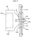
- a gap may be formed between the end of the supporting member 103b and the inner center plate 107b, too. Therefore, there is an issue that fluid such as air suctioned into the compression chamber leaks to the oscillator 103 side where the electromagnet, etc. is arranged, as indicated by arrows a1, a2 in Fig. 7 .
- the oscillator 103 can be tilted depending on how tightly the nut 106 is fastened, and the tilt, if any, allows the gap between the oscillator 103 and the electromagnet to vary easily, which leads to an issue of difficulty in stabilizing diaphragm pump performance among products.
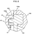
- a conventional electromagnetic vibrating diaphragm pump had a diaphragm support 108 and a partition wall 109a constituting a compression chamber (not illustrated) of a pump casing 109 sandwiching the outer periphery end 104a of a diaphragm 104 as shown in Fig. 8 , the outer periphery end 104a of the diaphragm 104 and the partition wall 109a of the compression chamber (not illustrated) of the pump casing 109 assembled by just being placed on each other.
- fluid suctioned into the compression chamber (not illustrated) of a pump leaks out of the pump casing 109 through the gap between a flange 104a of the diaphragm 104 and the partition wall 109a of the pump casing 109, following the order indicated by arrows b1-b3, and thus the amount of the fluid discharged from the compression chamber decreased to less than the amount of fluid suctioned into the compression chamber, to raise an issue of decreasing pump performance.
- the present invention was made in the light of the above conditions, and the object of the present invention is to provide an electromagnetic vibrating diaphragm pump which improves pump efficiency by preventing fluid such as air from leaking out to the oscillator side while stabilizing pump performance among products by maintaining a gap between the oscillator and the electromagnet constantly among products, and does not cause damage to components or harm to human bodies, etc. even when suctioning and discharging liquid or dangerous gas such as hydrogen.
- Another object of the present invention is to improve the pump efficiency by preventing the leakage of air, etc. from the abutment surface of the pump casing and the diaphragm.
- the electromagnetic vibrating diaphragm pump of the present invention comprises an oscillator having two magnets on at least one surface side of a plate-like supporting member made of non-magnetic material and having mounting screw parts fixed to both ends of a central axis of the supporting member, disc-shaped diaphragms fixed to the mounting screw parts at both ends of the supporting member, an electromagnet provided to face the magnets and pump casings fixed to respective outer peripheries of the diaphragms provided at both ends and individually covering the outer side of the diaphragms, wherein the diaphragm is sandwiched by an inner center plate provided on the magnet side of the diaphragm and an outer center plate provided on the side opposite to the magnet side of the diaphragm, the end of the oscillator is inserted into and fixed to a through hole provided at the center of the inner and outer center plates, a cylindrical projecting portion is formed at the center of the inner center plate on the oscillator side, and a concave groove capable of fitting the
- a protruding portion holding the side surfaces of both ends of the supporting member constituting the oscillator is formed on the surface of the inner center plate on its oscillator side so as to position the supporting member.
- the side surface herein includes, in addition to the side surface in the thickness direction of the plate-like supporting member, the side at the end of the planar part of the plate-like supporting member.
- the pump casing has a compression chamber adjacent to the diaphragm, an exhaust chamber connected to the compression chamber via an exhaust valve and a suction chamber connected to the compression chamber via a suction valve, and a rib digging into the diaphragm is formed on a joint surface jointing the diaphragm on the partition wall of the compression chamber.
- the electromagnetic vibrating diaphragm pump of the present invention is structured such that a cylindrical projecting portion is provided at the center of an inner center plate on its oscillator side and a concave groove capable of fitting the projecting portion is formed at the end of a supporting member of the oscillator, the projecting portion and the concave groove being sealed in an airtight manner with a ring-shaped elastic member inbetween. Therefore, with the groove formed beforehand on an outer periphery of a site where a mounting screw part is fixed at both ends of the supporting member of the oscillator and with an O-ring and the like inserted in this groove, by only press-fitting the mounting screw part into a through hole of the inner center plate, assembly work can be done and also airtight sealing can be ensured.
- this sealing is a closely attached sealing in radial direction, of the concave groove formed on the supporting member of the oscillator, the ring-shaped elastic member fitting into the concave groove and the cylindrical projecting portion, the dimension among components such as a gap between the oscillator and the electromagnet is not affected, regardless of the strength of the elasticity. Therefore, it is possible to stabilize pump performance among products.
- an unexpected external force is applied to the oscillator, for example during assembling stage, it has an effect of preventing damage to the diaphragm because of its absorptive capacity for such a large external force.
- the amount of fluid discharged from the compression chamber is not less than the amount of fluid suctioned into the compression chamber, and as a result, the decrease of pump performance can be prevented. Furthermore, if the fluid is liquid, it is possible to prevent pump failure due to short-circuited electromagnet coils, etc. when fluid penetrates to the oscillator side from taking place.
- a protruding portion for holding the side surfaces of both ends of the supporting member is formed such that the oscillator is prevented from rotating with respect to the inner center plate and the positioning of the supporting member can be performed easily, allowing stable operation of the pump.
- the protruding portion of the inner center plate can be served as a guide when inserting the mounting screw part of the oscillator into the through hole formed on the center plates, the supporting member of the oscillator and the inner center plate are assembled easily.
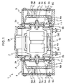
- Fig. 1 shows a sectional explanatory view of an electromagnetic vibrating diaphragm pump according to the first embodiment of the present invention
- Fig. 2 shows a schematic explanatory view of an electromagnet and oscillator part of the electromagnetic vibrating diaphragm pump shown in Fig. 1 .
- Fig. 1 shows a sectional explanatory view of an electromagnetic vibrating diaphragm pump according to the first embodiment of the present invention
- Fig. 2 shows a schematic explanatory view of an electromagnet and oscillator part of the electromagnetic vibrating diaphragm pump shown in Fig. 1 .
- Fig. 1 shows a sectional explanatory view of an electromagnetic vibrating diaphragm pump according to the first embodiment of the present invention
- Fig. 2 shows a schematic explanatory view of an electromagnet and oscillator part of the electromagnetic vibrating diaphragm pump shown in Fig. 1 .
- this electromagnetic vibrating diaphragm pump 1 (hereinafter abbreviated as pump) comprises an oscillator 2 having two magnets (permanent magnets) 2b1, 2b2 provided on a plate-like supporting member 2a made of nonmagnetic material and having mounting screw parts 2c fixed at both ends of a central axis of the supporting member 2a, disc-shaped diaphragms 3 fixed to the mounting screw parts 2c at both ends of the supporting member 2a of the oscillator 2, electromagnets 4a, 4b provided to face the magnets 2b1, 2b2, and pump casings 5 fixed to outer peripheries of the respective diaphragms 3 and covering the outer side of the respective diaphragms 3.
- the mounting screw part 2c is closely attached and fixed, for example by being integrally molded onto the supporting member 2a made of resin during the formation of the supporting member 2a by resin molding, etc.
- the diaphragm 3 is sandwiched by an inner center plate 6b provided on its magnet 2b1, 2b2 side of the diaphragm 3 and an outer center plate 6a provided on the side opposite to the magnet 2b1, 2b2 side of the diaphragm 3, and the mounting screw parts 2c fixed to the oscillator 2 are inserted into the through hole 6c provided at the center of the outer and inner center plates 6a, 6b and then fastened from outside through a washer 8 by a nut 9, such that the supporting member 2a of the oscillator 2 and the diaphragm 3 are fixed to each other.
- a cylindrical projecting portion 6b1 is formed at the center of the inner center plate 6b on its oscillator 2 side, a concave groove 2d capable of fitting the projecting portion 6b1 of the inner center plate 6b is formed at the end of the supporting member 2a of the oscillator 2, and the projecting portion 6b1 of the inner center plate 6b and the concave groove 2d of the supporting member 2a of the oscillator 2 are sealed in an airtight manner with an O-ring 7 inbetween as a ring-shaped elastic member.
- the electromagnets 4a, 4b comprise E-shaped electromagnet cores 4a1, 4b1 and electromagnet coils 4a2, 4b2 wound around the electromagnet cores 4a1, 4b1.
- two magnets 2b1, 2b2 are mounted to the supporting member 2a of the oscillator 2 and these magnets 2b1, 2b2 extend in width direction of the supporting member 2a.
- a plate-like ferrite magnet or rare earth magnet, etc. can be used as these magnets 2b1, 2b2, and the magnets 2b1, 2b2 are individually magnetized.
- either one of the electromagnets 4a, 4b has north pole at its center and south poles on both sides of it, while the other one has south pole at its center and north poles on its both sides, and these north pole and south pole change alternately in accordance with the change in the phase of an AC generator, such that the magnetic action of the magnets 2b1, 2b2 provided on the supporting member 2a of the oscillator 2 causes attraction and repulsion forces between the magnets 2b1, 2b2 so as to allow the oscillator 2 to move in a reciprocating motion in axial direction. Accordingly, the diaphragm 3 vibrates so that the pump 1 suctions and discharges fluid repeatedly.
- These magnets 2b1, 2b2 also can be tightly fixed to the supporting member 2a, for example by being integrally molded onto the resin of the supporting member 2a during the formation of the supporting member 2a by resin molding, etc..
- a diaphragm 4 can be formed of ethylene propylene rubber (EPDM) or fluoro-rubber, etc.
- the center plates 6a, 6b can be formed of metal or plastic, etc. Because this diaphragm 4 is sandwiched at its center by the outer center plate 6a and the inner center plate 6b, the through hole 6c communicates with from the outer center plate 6a to the inner center plate 6b through the diaphragm 3.
- the pump casing 5 is structured to be divided into a compression chamber 5A on the diaphragm 3 side, a suction chamber 5B and an exhaust chamber 5C by partition walls.
- a suction valve 5a is provided between the compression chamber 5A and the suction chamber 5B such that when the volume of the compression chamber 5A increases to decrease a pressure, the suction valve 5a opens to allow fluid to flow in from the suction chamber 5B, and when the volume of the compression chamber 5A decreases to increase pressure, the suction valve 5a closes.
- an exhaust valve 5b is provided between the compression chamber 5A and the exhaust chamber 5C so that when the volume of the compression chamber 5A decreases to increase pressure, this exhaust valve 5b opens to allow the fluid such as air in the compression chamber 5A to be discharged to the exhaust chamber 5C.
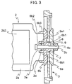
- a method of fixing the outer and inner center plates 6a, 6b sandwiching the diaphragm 3 at its center to the oscillator 2 will be described with reference to Fig. 3 .
- a cylindrical projecting portion 6b1 is formed at the center of the inner center plate 6b on its oscillator 2 side. While, at both ends of the supporting member 2a of the oscillator 2, a circular concave groove 2d terminated at the edges of side surfaces 2a2 (see Fig. 4 ) in thickness direction of the supporting member 2a at the end is formed such that the above-mentioned projecting portion 6b1 fits around the mounting screw part 2c.
- a cylindrical portion 2e is formed because of this concave groove 2d at the center of the end of the supporting member 2a, and a ring-shaped groove 2e1 where a ring-shaped elastic member 7 can be inserted is formed on the outer periphery of the cylindrical portion 2e.
- the mounting screw part 2c is press fitted and embedded into the through hole 6c extending through the center plates 6a, 6b and the diaphragm 4.
- the O-ring 7 is formed to have a larger diameter than that of the cylindrical portion 2e, it is pressurized more strongly to contact with an inner wall surface 6b2 of the projecting portion 6b1 of the inner center plate 6b, as well.
- the fluid is liquid
- a failure of the pump 1 due to a short circuit caused by the invasion of the fluid to the oscillator 2 side can be prevented from taking place.
- the pressure of the O-ring 7 is only in radial direction perpendicular to axial direction of the oscillator 2, it is not affected by how tightly the mounting screw part 2c is fastened at a screw clamp part, and dimensional variation among members, etc. such as decentralization of oscillator 2 is not caused. Therefore, the performance of the pump 1 can be stabilized among products.
- the oscillator 2 and the diaphragm 3 can be assembled, and thus work efficiency during the assembly of the oscillator 2 and the diaphragm 3 is not worsened. Additionally, even when an unexpected external force is applied to the oscillator 2 during an assembling stage of the oscillator 2 and the diaphragm 3 and the like, the diaphragm is not damaged because of absorptive capacity of the O-ring 7 for such a large external force.
- two U-shaped protruding portions 6b3, 6b4 are formed outside the cylindrical portion 6b1 on the inner center plate 6b in a manner to sandwich the cylindrical portion 6b 1, and the protruding portions 6b3, 6b4 are formed in a manner to entirely cover the outer peripheral side surface of the end of the supporting member 2a.
- These protruding portions 6b3, 6b4 are structured to hold side surfaces excluding the cylindrical portion 2e at both ends of the supporting member 2a of the oscillator 2.
- the "side surfaces” include a surface 2a1 in the thickness direction of the oscillator 2 and a surface 2a2 at the end of the planar part as shown in Fig. 4 .
- the side surface 2a2 of the supporting member 2a of the oscillator 2 is stuck at the protruding portions 6b3, 6b4 of the inner center plate 6b, and thus the oscillator 2 can be prevented from rotating.
- the pump 1 can be operated in a stable manner.
- the protruding portions 6b3, 6b4 serve as a guide when inserting the mounting screw part 2c of the oscillator 2 into the through hole 6c extending through the diaphragm 3 and the center plates 6a, 6b, so as to make the insertion work easy.
- the diaphragm 3 has a flange 3a formed on the outer peripheral edge and this flange 3a is sandwiched by a diaphragm support 11 and the partition wall 5A1 of the compression chamber 5A of the pump casing 5 such that diaphragm 3 is fixed.
- a circular rib 5A3 is provided, by integral molding, on the abutment surface 5A2 jointing the flange 3a of the diaphragm 3 on the partition wall 5A1 of the compression chamber 5A, and this circular rib 5A3 digs into the abutment surface 3a1 jointing the partition wall 5A of the pump casing 5 at the flange 3a of the diaphragm 3. Therefore, the sealing between the partition wall 5A1 of the compression chamber 5A of the pump casing 5 and the flange 3a of the diaphragm 3 can be improved. As a result, the amount of fluid suctioned into the compression chamber 5A is prevented from decreasing to less than the amount of fluid discharged from the compression chamber 5A, and it is possible to prevent the decrease of the performance of the pump.
- the circular rib 5A3 is provided on the partition wall 5A of the pump casing 5 as done in this embodiment, the circular rib 5A3 is not affected by the deformation of the diaphragm 3 during the operation of the pump 1, and thus the sealing as a rib is stabilized so that operation status of the pump 1 can be stabilized eventually.
Landscapes
- Engineering & Computer Science (AREA)
- Mechanical Engineering (AREA)
- General Engineering & Computer Science (AREA)
- Physics & Mathematics (AREA)
- Fluid Mechanics (AREA)
- Reciprocating Pumps (AREA)
Claims (10)
- pompe à diaphragme vibrant électromagnétique (1) comprenant :un oscillateur (2) comportant deux aimants (2b1, 2b2) placés sur au moins un côté de surface d'un élément de support en plaque (22) fait de matériau non magnétique et comportant des parties de vis de montage fixées aux deux extrémités d'un axe central de l'élément de support (22) ;des diaphragmes en forme de disque fixés sur les parties de vis de montage aux deux extrémités de l'élément de support (22) ;un électroaimant (4a, 4b) placé pour faire face aux aimants ; etdes carters de pompe fixés sur des périphéries extérieures respectives des diaphragmes placés aux deux extrémités et couvrant individuellement le côté extérieur des diaphragmes,dans laquelle le diaphragme (3) est pris en sandwich par une plaque centrale intérieure (6b) placée sur le côté aimant du diaphragme (3) et une plaque centrale extérieure (6a) disposée sur le côté opposé au côté aimant du diaphragme, l'extrémité de l'oscillateur (2) est insérée dans et fixée à un trou traversant placé au centre des plaques centrales intérieure et extérieure, et une partie saillante cylindrique (6b1) est formée au centre de la plaque centrale intérieure du côté oscillateur, caractérisé en ce qu'une rainure concave (2d) dans laquelle peut être ajustée la partie saillante (6b1) est formée à l'extrémité de l'élément de support de l'oscillateur (2) et un élément élastique en forme d'anneau est placé entre la périphérie extérieure d'une partie cylindrique formée quand la rainure concave (2d) est formée et la périphérie intérieure de la partie saillante cylindrique, de telle manière qu'une fuite depuis une partie espacée entre le trou traversant des plaques centrales intérieure et extérieure et l'extrémité de l'oscillateur (2) est empêchée d'une manière étanche à l'air.
- Pompe à diaphragme vibrant électromagnétique (1) selon la revendication 1, dans laquelle une partie saillante pour maintenir les surfaces latérales des deux extrémités de l'élément de support (2a) constituant l'oscillateur (2) est formée sur la surface de la plaque centrale intérieure sur son côté oscillateur (2) de façon à positionner l'élément de support.
- Pompe à diaphragme vibrant électromagnétique (1) selon la revendication 2, dans laquelle les parties saillantes sont formées de manière à couvrir entièrement la surface latérale périphérique extérieure de l'extrémité de l'élément de support (2a).
- Pompe à diaphragme vibrant électromagnétique (1) selon l'une quelconque des revendications 1-3, dans laquelle la rainure concave (2d) est une rainure concave circulaire se terminant au niveau des bords des surfaces latérales dans la direction d'épaisseur de l'élément de support à l'extrémité.
- Pompe à diaphragme (3) vibrant électromagnétique (1) selon l'une quelconque des revendications 1-4, dans laquelle le carter de pompe comporte une chambre de compression adjacente au diaphragme, une chambre d'échappement reliée à la chambre de compression par l'intermédiaire d'une soupape d'échappement (5b) et une chambre d'aspiration reliée à la chambre de compression via une soupape d'aspiration (5a), et une nervure entrant dans le diaphragme (3) est formée sur une surface de joint joignant le diaphragme sur une paroi de séparation de la chambre de compression.
- Pompe à diaphragme vibrant électromagnétique (1) selon la revendication 5, dans laquelle la nervure est formée de façon à être circulaire et entre dans une partie de rebord formée à l'extrémité du diaphragme (3) d'une manière circulaire de telle manière que la paroi de séparation et le diaphragme (3) sont joints.
- Pompe à diaphragme vibrant électromagnétique (1) selon la revendication 6, dans laquelle la partie de vis de montage est fixée d'un seul bloc à l'élément de support fait de résine pendant la formation de l'élément de support par moulage de résine.
- Pompe à diaphragme vibrant électromagnétique (1) selon l'une quelconque des revendications 1-7, dans laquelle le diaphragme (3) est formé de caoutchouc éthylène-propylène (EPDM) ou de caoutchouc fluoré compact.
- Pompe à diaphragme vibrant électromagnétique (1) selon l'une quelconque des revendications 1-8, dans laquelle les aimants (2b1, 2b2) sont des aimants permanents constitués d'un aimant en terres rares ou d'un aimant en ferrite en forme de plaque.
- Pompe à diaphragme vibrant électromagnétique (1) selon la revendication 9, dans laquelle les aimants (2b1, 2b2) sont fixés d'un seul bloc sur l'élément de support fait en résine pendant la formation de l'élément de support par moulage de résine.
Applications Claiming Priority (2)
| Application Number | Priority Date | Filing Date | Title |
|---|---|---|---|
| JP2011091237A JP2012225190A (ja) | 2011-04-15 | 2011-04-15 | 電磁振動型ダイヤフラムポンプ |
| PCT/JP2012/059647 WO2012141125A1 (fr) | 2011-04-15 | 2012-04-09 | Pompe électromagnétique à membranes oscillantes |
Publications (3)
| Publication Number | Publication Date |
|---|---|
| EP2634429A1 EP2634429A1 (fr) | 2013-09-04 |
| EP2634429A4 EP2634429A4 (fr) | 2015-08-05 |
| EP2634429B1 true EP2634429B1 (fr) | 2016-04-06 |
Family
ID=47009298
Family Applications (1)
| Application Number | Title | Priority Date | Filing Date |
|---|---|---|---|
| EP12771844.3A Not-in-force EP2634429B1 (fr) | 2011-04-15 | 2012-04-09 | Pompe électromagnétique à membranes oscillantes |
Country Status (6)
| Country | Link |
|---|---|
| US (1) | US20140023532A1 (fr) |
| EP (1) | EP2634429B1 (fr) |
| JP (1) | JP2012225190A (fr) |
| KR (1) | KR20140011381A (fr) |
| DK (1) | DK2634429T3 (fr) |
| WO (1) | WO2012141125A1 (fr) |
Families Citing this family (8)
| Publication number | Priority date | Publication date | Assignee | Title |
|---|---|---|---|---|
| US9920752B2 (en) * | 2012-11-14 | 2018-03-20 | Koninklijke Philips N.V. | Fluid pump |
| US20180038363A1 (en) * | 2016-08-08 | 2018-02-08 | Jet Fluid Systems Inc. | Double diaphragm pumps with an electromagnetic drive |
| CN105179211A (zh) * | 2015-08-25 | 2015-12-23 | 李喆 | 一种逆渗透增压泵工作水腔的加强密封结构 |
| JP2017044178A (ja) * | 2015-08-28 | 2017-03-02 | フジクリーン工業株式会社 | 電磁式ポンプ |
| DE102017108196A1 (de) * | 2016-04-18 | 2017-10-19 | Ingersoll-Rand Company | Direkt angetriebener linearmotor für herkömmlich angeordnete doppelmembranpumpe |
| US11002270B2 (en) | 2016-04-18 | 2021-05-11 | Ingersoll-Rand Industrial U.S., Inc. | Cooling methods for electrically operated diaphragm pumps |
| DE102016008783A1 (de) * | 2016-07-22 | 2018-01-25 | Knf Flodos Ag | Oszillierende Verdrängerpumpe mit elektrodynamischem Antrieb und Verfahren zu deren Betrieb |
| CN113906215B (zh) * | 2019-06-03 | 2024-03-29 | 固瑞克明尼苏达有限公司 | 用于电动泵的隔膜泵驱动器 |
Family Cites Families (12)
| Publication number | Priority date | Publication date | Assignee | Title |
|---|---|---|---|---|
| JPS57120781U (fr) * | 1981-01-23 | 1982-07-27 | ||
| US5013223A (en) * | 1987-08-20 | 1991-05-07 | Takatsuki Electric Mfg. Co., Ltd. | Diaphragm-type air pump |
| JP2531877Y2 (ja) * | 1988-12-15 | 1997-04-09 | 日東工器株式会社 | 電磁式ダイアフラムポンプ |
| JP2000130340A (ja) * | 1998-10-28 | 2000-05-12 | Fujikura Rubber Ltd | 電磁式ダイヤフラムポンプ |
| JP2000170662A (ja) * | 1998-12-03 | 2000-06-20 | Fujikura Rubber Ltd | 電磁式ダイヤフラムポンプおよびその振動系の固有振動数の調整方法 |
| DE10004520B4 (de) * | 1999-11-08 | 2006-09-14 | Nitto Kohki Co., Ltd. | Elektromagnetische Membranpumpe |
| JP3706316B2 (ja) | 2001-07-19 | 2005-10-12 | 藤倉ゴム工業株式会社 | 電磁式ダイヤフラムポンプ |
| JP2004138009A (ja) * | 2002-10-18 | 2004-05-13 | Techno Takatsuki Co Ltd | 電磁振動型ポンプ |
| US6883417B2 (en) * | 2003-03-19 | 2005-04-26 | Ingersoll-Rand Company | Connecting configuration for a diaphragm in a diaphragm pump |
| JP2005180224A (ja) * | 2003-12-17 | 2005-07-07 | Nok Corp | ダイアフラムおよびその取付構造 |
| JP2008150959A (ja) * | 2006-12-14 | 2008-07-03 | Techno Takatsuki Co Ltd | ダイヤフラムの中央保持組立体 |
| JP5927766B2 (ja) * | 2011-03-11 | 2016-06-01 | 株式会社ジェイテクト | 電動ポンプユニット |
-
2011
- 2011-04-15 JP JP2011091237A patent/JP2012225190A/ja not_active Withdrawn
-
2012
- 2012-04-09 DK DK12771844.3T patent/DK2634429T3/en active
- 2012-04-09 EP EP12771844.3A patent/EP2634429B1/fr not_active Not-in-force
- 2012-04-09 KR KR1020137027017A patent/KR20140011381A/ko not_active Withdrawn
- 2012-04-09 US US14/009,765 patent/US20140023532A1/en not_active Abandoned
- 2012-04-09 WO PCT/JP2012/059647 patent/WO2012141125A1/fr not_active Ceased
Also Published As
| Publication number | Publication date |
|---|---|
| WO2012141125A1 (fr) | 2012-10-18 |
| DK2634429T3 (en) | 2016-06-27 |
| EP2634429A4 (fr) | 2015-08-05 |
| EP2634429A1 (fr) | 2013-09-04 |
| KR20140011381A (ko) | 2014-01-28 |
| US20140023532A1 (en) | 2014-01-23 |
| JP2012225190A (ja) | 2012-11-15 |
Similar Documents
| Publication | Publication Date | Title |
|---|---|---|
| EP2634429B1 (fr) | Pompe électromagnétique à membranes oscillantes | |
| US9976546B2 (en) | Electromagnetic vibrating diaphragm pump | |
| US20030082056A1 (en) | Electromagnetic oscillating type pump and method for manufacturing the same | |
| EP2639455B1 (fr) | Pompe électromagnétique à diaphragme vibrant | |
| WO2021000074A1 (fr) | Moteur à vibrations | |
| JP6884822B2 (ja) | リニア振動モータ | |
| JP2004282943A (ja) | リニアアクチュエータ、それを用いたポンプ装置並びにコンプレッサー装置 | |
| JP6062179B2 (ja) | センタリング機能付きセンタープレート搭載電磁駆動型流体ポンプ | |
| JP2005325780A (ja) | 往復動式ポンプ | |
| JP4502522B2 (ja) | ピストン式電磁振動型ポンプ | |
| JP2807746B2 (ja) | 振動型ポンプ | |
| KR102242373B1 (ko) | 리니어 압축기 | |
| JP5514974B2 (ja) | ポンプ | |
| JP3005780U (ja) | 振動型ポンプ | |
| KR102624668B1 (ko) | 안전 스위치 부착 및 용접형 다이어프램 펌프 | |
| JP3390094B2 (ja) | 振動型ダイヤフラムポンプ | |
| JPH07310668A (ja) | 電磁式エアーポンプ | |
| KR200196593Y1 (ko) | 솔레노이드식 다이아프램 펌프 | |
| JPS6237982Y2 (fr) | ||
| JP2006152986A (ja) | 電磁式ダイヤフラムポンプ | |
| KR101981719B1 (ko) | 전자기식 에어 펌프 | |
| JP3504516B2 (ja) | 電磁ポンプ | |
| KR200248289Y1 (ko) | 에어펌프용 하우징 | |
| JP2006050787A (ja) | リニアアクチュエータ、それを用いたポンプ装置並びにコンプレッサー装置 | |
| JP2002174177A (ja) | 振動型圧縮機の連結リード線組み付け体 |
Legal Events
| Date | Code | Title | Description |
|---|---|---|---|
| PUAI | Public reference made under article 153(3) epc to a published international application that has entered the european phase |
Free format text: ORIGINAL CODE: 0009012 |
|
| 17P | Request for examination filed |
Effective date: 20130527 |
|
| AK | Designated contracting states |
Kind code of ref document: A1 Designated state(s): AL AT BE BG CH CY CZ DE DK EE ES FI FR GB GR HR HU IE IS IT LI LT LU LV MC MK MT NL NO PL PT RO RS SE SI SK SM TR |
|
| DAX | Request for extension of the european patent (deleted) | ||
| RA4 | Supplementary search report drawn up and despatched (corrected) |
Effective date: 20150702 |
|
| RIC1 | Information provided on ipc code assigned before grant |
Ipc: F04B 45/047 20060101ALI20150626BHEP Ipc: F04B 45/04 20060101AFI20150626BHEP |
|
| GRAP | Despatch of communication of intention to grant a patent |
Free format text: ORIGINAL CODE: EPIDOSNIGR1 |
|
| INTG | Intention to grant announced |
Effective date: 20151103 |
|
| GRAS | Grant fee paid |
Free format text: ORIGINAL CODE: EPIDOSNIGR3 |
|
| GRAA | (expected) grant |
Free format text: ORIGINAL CODE: 0009210 |
|
| AK | Designated contracting states |
Kind code of ref document: B1 Designated state(s): AL AT BE BG CH CY CZ DE DK EE ES FI FR GB GR HR HU IE IS IT LI LT LU LV MC MK MT NL NO PL PT RO RS SE SI SK SM TR |
|
| REG | Reference to a national code |
Ref country code: GB Ref legal event code: FG4D |
|
| REG | Reference to a national code |
Ref country code: AT Ref legal event code: REF Ref document number: 788141 Country of ref document: AT Kind code of ref document: T Effective date: 20160415 Ref country code: CH Ref legal event code: EP |
|
| REG | Reference to a national code |
Ref country code: FR Ref legal event code: PLFP Year of fee payment: 5 |
|
| REG | Reference to a national code |
Ref country code: IE Ref legal event code: FG4D |
|
| REG | Reference to a national code |
Ref country code: DE Ref legal event code: R096 Ref document number: 602012016716 Country of ref document: DE |
|
| REG | Reference to a national code |
Ref country code: DK Ref legal event code: T3 Effective date: 20160623 |
|
| PGFP | Annual fee paid to national office [announced via postgrant information from national office to epo] |
Ref country code: IE Payment date: 20160408 Year of fee payment: 5 Ref country code: GB Payment date: 20160406 Year of fee payment: 5 Ref country code: DE Payment date: 20160530 Year of fee payment: 5 |
|
| REG | Reference to a national code |
Ref country code: LT Ref legal event code: MG4D Ref country code: NL Ref legal event code: MP Effective date: 20160406 |
|
| REG | Reference to a national code |
Ref country code: AT Ref legal event code: MK05 Ref document number: 788141 Country of ref document: AT Kind code of ref document: T Effective date: 20160406 |
|
| PG25 | Lapsed in a contracting state [announced via postgrant information from national office to epo] |
Ref country code: BE Free format text: LAPSE BECAUSE OF NON-PAYMENT OF DUE FEES Effective date: 20160430 |
|
| PGFP | Annual fee paid to national office [announced via postgrant information from national office to epo] |
Ref country code: FR Payment date: 20160422 Year of fee payment: 5 |
|
| PG25 | Lapsed in a contracting state [announced via postgrant information from national office to epo] |
Ref country code: NL Free format text: LAPSE BECAUSE OF FAILURE TO SUBMIT A TRANSLATION OF THE DESCRIPTION OR TO PAY THE FEE WITHIN THE PRESCRIBED TIME-LIMIT Effective date: 20160406 |
|
| PG25 | Lapsed in a contracting state [announced via postgrant information from national office to epo] |
Ref country code: NO Free format text: LAPSE BECAUSE OF FAILURE TO SUBMIT A TRANSLATION OF THE DESCRIPTION OR TO PAY THE FEE WITHIN THE PRESCRIBED TIME-LIMIT Effective date: 20160706 Ref country code: PL Free format text: LAPSE BECAUSE OF FAILURE TO SUBMIT A TRANSLATION OF THE DESCRIPTION OR TO PAY THE FEE WITHIN THE PRESCRIBED TIME-LIMIT Effective date: 20160406 Ref country code: IS Free format text: LAPSE BECAUSE OF FAILURE TO SUBMIT A TRANSLATION OF THE DESCRIPTION OR TO PAY THE FEE WITHIN THE PRESCRIBED TIME-LIMIT Effective date: 20160806 Ref country code: FI Free format text: LAPSE BECAUSE OF FAILURE TO SUBMIT A TRANSLATION OF THE DESCRIPTION OR TO PAY THE FEE WITHIN THE PRESCRIBED TIME-LIMIT Effective date: 20160406 Ref country code: LT Free format text: LAPSE BECAUSE OF FAILURE TO SUBMIT A TRANSLATION OF THE DESCRIPTION OR TO PAY THE FEE WITHIN THE PRESCRIBED TIME-LIMIT Effective date: 20160406 |
|
| PGFP | Annual fee paid to national office [announced via postgrant information from national office to epo] |
Ref country code: DK Payment date: 20160713 Year of fee payment: 5 |
|
| PG25 | Lapsed in a contracting state [announced via postgrant information from national office to epo] |
Ref country code: SE Free format text: LAPSE BECAUSE OF FAILURE TO SUBMIT A TRANSLATION OF THE DESCRIPTION OR TO PAY THE FEE WITHIN THE PRESCRIBED TIME-LIMIT Effective date: 20160406 Ref country code: GR Free format text: LAPSE BECAUSE OF FAILURE TO SUBMIT A TRANSLATION OF THE DESCRIPTION OR TO PAY THE FEE WITHIN THE PRESCRIBED TIME-LIMIT Effective date: 20160707 Ref country code: HR Free format text: LAPSE BECAUSE OF FAILURE TO SUBMIT A TRANSLATION OF THE DESCRIPTION OR TO PAY THE FEE WITHIN THE PRESCRIBED TIME-LIMIT Effective date: 20160406 Ref country code: RS Free format text: LAPSE BECAUSE OF FAILURE TO SUBMIT A TRANSLATION OF THE DESCRIPTION OR TO PAY THE FEE WITHIN THE PRESCRIBED TIME-LIMIT Effective date: 20160406 Ref country code: PT Free format text: LAPSE BECAUSE OF FAILURE TO SUBMIT A TRANSLATION OF THE DESCRIPTION OR TO PAY THE FEE WITHIN THE PRESCRIBED TIME-LIMIT Effective date: 20160808 Ref country code: LV Free format text: LAPSE BECAUSE OF FAILURE TO SUBMIT A TRANSLATION OF THE DESCRIPTION OR TO PAY THE FEE WITHIN THE PRESCRIBED TIME-LIMIT Effective date: 20160406 Ref country code: ES Free format text: LAPSE BECAUSE OF FAILURE TO SUBMIT A TRANSLATION OF THE DESCRIPTION OR TO PAY THE FEE WITHIN THE PRESCRIBED TIME-LIMIT Effective date: 20160406 Ref country code: AT Free format text: LAPSE BECAUSE OF FAILURE TO SUBMIT A TRANSLATION OF THE DESCRIPTION OR TO PAY THE FEE WITHIN THE PRESCRIBED TIME-LIMIT Effective date: 20160406 |
|
| REG | Reference to a national code |
Ref country code: CH Ref legal event code: PL |
|
| PG25 | Lapsed in a contracting state [announced via postgrant information from national office to epo] |
Ref country code: BE Free format text: LAPSE BECAUSE OF FAILURE TO SUBMIT A TRANSLATION OF THE DESCRIPTION OR TO PAY THE FEE WITHIN THE PRESCRIBED TIME-LIMIT Effective date: 20160406 Ref country code: IT Free format text: LAPSE BECAUSE OF FAILURE TO SUBMIT A TRANSLATION OF THE DESCRIPTION OR TO PAY THE FEE WITHIN THE PRESCRIBED TIME-LIMIT Effective date: 20160406 |
|
| REG | Reference to a national code |
Ref country code: DE Ref legal event code: R097 Ref document number: 602012016716 Country of ref document: DE |
|
| PG25 | Lapsed in a contracting state [announced via postgrant information from national office to epo] |
Ref country code: CZ Free format text: LAPSE BECAUSE OF FAILURE TO SUBMIT A TRANSLATION OF THE DESCRIPTION OR TO PAY THE FEE WITHIN THE PRESCRIBED TIME-LIMIT Effective date: 20160406 Ref country code: LI Free format text: LAPSE BECAUSE OF NON-PAYMENT OF DUE FEES Effective date: 20160430 Ref country code: MC Free format text: LAPSE BECAUSE OF FAILURE TO SUBMIT A TRANSLATION OF THE DESCRIPTION OR TO PAY THE FEE WITHIN THE PRESCRIBED TIME-LIMIT Effective date: 20160406 Ref country code: RO Free format text: LAPSE BECAUSE OF FAILURE TO SUBMIT A TRANSLATION OF THE DESCRIPTION OR TO PAY THE FEE WITHIN THE PRESCRIBED TIME-LIMIT Effective date: 20160406 Ref country code: CH Free format text: LAPSE BECAUSE OF NON-PAYMENT OF DUE FEES Effective date: 20160430 Ref country code: SK Free format text: LAPSE BECAUSE OF FAILURE TO SUBMIT A TRANSLATION OF THE DESCRIPTION OR TO PAY THE FEE WITHIN THE PRESCRIBED TIME-LIMIT Effective date: 20160406 Ref country code: EE Free format text: LAPSE BECAUSE OF FAILURE TO SUBMIT A TRANSLATION OF THE DESCRIPTION OR TO PAY THE FEE WITHIN THE PRESCRIBED TIME-LIMIT Effective date: 20160406 |
|
| PLBE | No opposition filed within time limit |
Free format text: ORIGINAL CODE: 0009261 |
|
| STAA | Information on the status of an ep patent application or granted ep patent |
Free format text: STATUS: NO OPPOSITION FILED WITHIN TIME LIMIT |
|
| PG25 | Lapsed in a contracting state [announced via postgrant information from national office to epo] |
Ref country code: SM Free format text: LAPSE BECAUSE OF FAILURE TO SUBMIT A TRANSLATION OF THE DESCRIPTION OR TO PAY THE FEE WITHIN THE PRESCRIBED TIME-LIMIT Effective date: 20160406 |
|
| 26N | No opposition filed |
Effective date: 20170110 |
|
| PG25 | Lapsed in a contracting state [announced via postgrant information from national office to epo] |
Ref country code: SI Free format text: LAPSE BECAUSE OF FAILURE TO SUBMIT A TRANSLATION OF THE DESCRIPTION OR TO PAY THE FEE WITHIN THE PRESCRIBED TIME-LIMIT Effective date: 20160406 |
|
| REG | Reference to a national code |
Ref country code: DE Ref legal event code: R119 Ref document number: 602012016716 Country of ref document: DE |
|
| REG | Reference to a national code |
Ref country code: DK Ref legal event code: EBP Effective date: 20170430 |
|
| GBPC | Gb: european patent ceased through non-payment of renewal fee |
Effective date: 20170409 |
|
| REG | Reference to a national code |
Ref country code: IE Ref legal event code: MM4A |
|
| REG | Reference to a national code |
Ref country code: FR Ref legal event code: ST Effective date: 20171229 |
|
| PG25 | Lapsed in a contracting state [announced via postgrant information from national office to epo] |
Ref country code: FR Free format text: LAPSE BECAUSE OF NON-PAYMENT OF DUE FEES Effective date: 20170502 Ref country code: DE Free format text: LAPSE BECAUSE OF NON-PAYMENT OF DUE FEES Effective date: 20171103 |
|
| PG25 | Lapsed in a contracting state [announced via postgrant information from national office to epo] |
Ref country code: GB Free format text: LAPSE BECAUSE OF NON-PAYMENT OF DUE FEES Effective date: 20170409 |
|
| PG25 | Lapsed in a contracting state [announced via postgrant information from national office to epo] |
Ref country code: IE Free format text: LAPSE BECAUSE OF NON-PAYMENT OF DUE FEES Effective date: 20170409 Ref country code: DK Free format text: LAPSE BECAUSE OF NON-PAYMENT OF DUE FEES Effective date: 20170430 |
|
| PG25 | Lapsed in a contracting state [announced via postgrant information from national office to epo] |
Ref country code: HU Free format text: LAPSE BECAUSE OF FAILURE TO SUBMIT A TRANSLATION OF THE DESCRIPTION OR TO PAY THE FEE WITHIN THE PRESCRIBED TIME-LIMIT; INVALID AB INITIO Effective date: 20120409 Ref country code: CY Free format text: LAPSE BECAUSE OF FAILURE TO SUBMIT A TRANSLATION OF THE DESCRIPTION OR TO PAY THE FEE WITHIN THE PRESCRIBED TIME-LIMIT Effective date: 20160406 |
|
| PG25 | Lapsed in a contracting state [announced via postgrant information from national office to epo] |
Ref country code: MT Free format text: LAPSE BECAUSE OF NON-PAYMENT OF DUE FEES Effective date: 20160430 Ref country code: MK Free format text: LAPSE BECAUSE OF FAILURE TO SUBMIT A TRANSLATION OF THE DESCRIPTION OR TO PAY THE FEE WITHIN THE PRESCRIBED TIME-LIMIT Effective date: 20160406 Ref country code: TR Free format text: LAPSE BECAUSE OF FAILURE TO SUBMIT A TRANSLATION OF THE DESCRIPTION OR TO PAY THE FEE WITHIN THE PRESCRIBED TIME-LIMIT Effective date: 20160406 Ref country code: LU Free format text: LAPSE BECAUSE OF NON-PAYMENT OF DUE FEES Effective date: 20160409 |
|
| PG25 | Lapsed in a contracting state [announced via postgrant information from national office to epo] |
Ref country code: BG Free format text: LAPSE BECAUSE OF FAILURE TO SUBMIT A TRANSLATION OF THE DESCRIPTION OR TO PAY THE FEE WITHIN THE PRESCRIBED TIME-LIMIT Effective date: 20160406 |
|
| PG25 | Lapsed in a contracting state [announced via postgrant information from national office to epo] |
Ref country code: AL Free format text: LAPSE BECAUSE OF FAILURE TO SUBMIT A TRANSLATION OF THE DESCRIPTION OR TO PAY THE FEE WITHIN THE PRESCRIBED TIME-LIMIT Effective date: 20160406 |