EP2634431A1 - Flügelzellenpumpe - Google Patents
Flügelzellenpumpe Download PDFInfo
- Publication number
- EP2634431A1 EP2634431A1 EP13167793.2A EP13167793A EP2634431A1 EP 2634431 A1 EP2634431 A1 EP 2634431A1 EP 13167793 A EP13167793 A EP 13167793A EP 2634431 A1 EP2634431 A1 EP 2634431A1
- Authority
- EP
- European Patent Office
- Prior art keywords
- passage
- rotor
- oil supply
- vane
- pump room
- Prior art date
- Legal status (The legal status is an assumption and is not a legal conclusion. Google has not performed a legal analysis and makes no representation as to the accuracy of the status listed.)
- Withdrawn
Links
Images

Classifications
-
- F—MECHANICAL ENGINEERING; LIGHTING; HEATING; WEAPONS; BLASTING
- F04—POSITIVE - DISPLACEMENT MACHINES FOR LIQUIDS; PUMPS FOR LIQUIDS OR ELASTIC FLUIDS
- F04C—ROTARY-PISTON, OR OSCILLATING-PISTON, POSITIVE-DISPLACEMENT MACHINES FOR LIQUIDS; ROTARY-PISTON, OR OSCILLATING-PISTON, POSITIVE-DISPLACEMENT PUMPS
- F04C18/00—Rotary-piston pumps specially adapted for elastic fluids
- F04C18/30—Rotary-piston pumps specially adapted for elastic fluids having the characteristics covered by two or more of groups F04C18/02, F04C18/08, F04C18/22, F04C18/24, F04C18/48, or having the characteristics covered by one of these groups together with some other type of movement between co-operating members
- F04C18/34—Rotary-piston pumps specially adapted for elastic fluids having the characteristics covered by two or more of groups F04C18/02, F04C18/08, F04C18/22, F04C18/24, F04C18/48, or having the characteristics covered by one of these groups together with some other type of movement between co-operating members having the movement defined in group F04C18/08 or F04C18/22 and relative reciprocation between the co-operating members
- F04C18/344—Rotary-piston pumps specially adapted for elastic fluids having the characteristics covered by two or more of groups F04C18/02, F04C18/08, F04C18/22, F04C18/24, F04C18/48, or having the characteristics covered by one of these groups together with some other type of movement between co-operating members having the movement defined in group F04C18/08 or F04C18/22 and relative reciprocation between the co-operating members with vanes reciprocating with respect to the inner member
-
- F—MECHANICAL ENGINEERING; LIGHTING; HEATING; WEAPONS; BLASTING
- F04—POSITIVE - DISPLACEMENT MACHINES FOR LIQUIDS; PUMPS FOR LIQUIDS OR ELASTIC FLUIDS
- F04C—ROTARY-PISTON, OR OSCILLATING-PISTON, POSITIVE-DISPLACEMENT MACHINES FOR LIQUIDS; ROTARY-PISTON, OR OSCILLATING-PISTON, POSITIVE-DISPLACEMENT PUMPS
- F04C29/00—Component parts, details or accessories of pumps or pumping installations, not provided for in groups F04C18/00 - F04C28/00
- F04C29/02—Lubrication; Lubricant separation
- F04C29/028—Means for improving or restricting lubricant flow
-
- F—MECHANICAL ENGINEERING; LIGHTING; HEATING; WEAPONS; BLASTING
- F04—POSITIVE - DISPLACEMENT MACHINES FOR LIQUIDS; PUMPS FOR LIQUIDS OR ELASTIC FLUIDS
- F04C—ROTARY-PISTON, OR OSCILLATING-PISTON, POSITIVE-DISPLACEMENT MACHINES FOR LIQUIDS; ROTARY-PISTON, OR OSCILLATING-PISTON, POSITIVE-DISPLACEMENT PUMPS
- F04C18/00—Rotary-piston pumps specially adapted for elastic fluids
- F04C18/30—Rotary-piston pumps specially adapted for elastic fluids having the characteristics covered by two or more of groups F04C18/02, F04C18/08, F04C18/22, F04C18/24, F04C18/48, or having the characteristics covered by one of these groups together with some other type of movement between co-operating members
- F04C18/34—Rotary-piston pumps specially adapted for elastic fluids having the characteristics covered by two or more of groups F04C18/02, F04C18/08, F04C18/22, F04C18/24, F04C18/48, or having the characteristics covered by one of these groups together with some other type of movement between co-operating members having the movement defined in group F04C18/08 or F04C18/22 and relative reciprocation between the co-operating members
- F04C18/344—Rotary-piston pumps specially adapted for elastic fluids having the characteristics covered by two or more of groups F04C18/02, F04C18/08, F04C18/22, F04C18/24, F04C18/48, or having the characteristics covered by one of these groups together with some other type of movement between co-operating members having the movement defined in group F04C18/08 or F04C18/22 and relative reciprocation between the co-operating members with vanes reciprocating with respect to the inner member
- F04C18/3441—Rotary-piston pumps specially adapted for elastic fluids having the characteristics covered by two or more of groups F04C18/02, F04C18/08, F04C18/22, F04C18/24, F04C18/48, or having the characteristics covered by one of these groups together with some other type of movement between co-operating members having the movement defined in group F04C18/08 or F04C18/22 and relative reciprocation between the co-operating members with vanes reciprocating with respect to the inner member the inner and outer member being in contact along one line or continuous surface substantially parallel to the axis of rotation
- F04C18/3442—Rotary-piston pumps specially adapted for elastic fluids having the characteristics covered by two or more of groups F04C18/02, F04C18/08, F04C18/22, F04C18/24, F04C18/48, or having the characteristics covered by one of these groups together with some other type of movement between co-operating members having the movement defined in group F04C18/08 or F04C18/22 and relative reciprocation between the co-operating members with vanes reciprocating with respect to the inner member the inner and outer member being in contact along one line or continuous surface substantially parallel to the axis of rotation the surfaces of the inner and outer member, forming the inlet and outlet opening
-
- F—MECHANICAL ENGINEERING; LIGHTING; HEATING; WEAPONS; BLASTING
- F04—POSITIVE - DISPLACEMENT MACHINES FOR LIQUIDS; PUMPS FOR LIQUIDS OR ELASTIC FLUIDS
- F04C—ROTARY-PISTON, OR OSCILLATING-PISTON, POSITIVE-DISPLACEMENT MACHINES FOR LIQUIDS; ROTARY-PISTON, OR OSCILLATING-PISTON, POSITIVE-DISPLACEMENT PUMPS
- F04C25/00—Adaptations of pumps for special use of pumps for elastic fluids
- F04C25/02—Adaptations of pumps for special use of pumps for elastic fluids for producing high vacuum
-
- F—MECHANICAL ENGINEERING; LIGHTING; HEATING; WEAPONS; BLASTING
- F04—POSITIVE - DISPLACEMENT MACHINES FOR LIQUIDS; PUMPS FOR LIQUIDS OR ELASTIC FLUIDS
- F04C—ROTARY-PISTON, OR OSCILLATING-PISTON, POSITIVE-DISPLACEMENT MACHINES FOR LIQUIDS; ROTARY-PISTON, OR OSCILLATING-PISTON, POSITIVE-DISPLACEMENT PUMPS
- F04C28/00—Control of, monitoring of, or safety arrangements for, pumps or pumping installations specially adapted for elastic fluids
- F04C28/06—Control of, monitoring of, or safety arrangements for, pumps or pumping installations specially adapted for elastic fluids specially adapted for stopping, starting, idling or no-load operation
-
- F—MECHANICAL ENGINEERING; LIGHTING; HEATING; WEAPONS; BLASTING
- F04—POSITIVE - DISPLACEMENT MACHINES FOR LIQUIDS; PUMPS FOR LIQUIDS OR ELASTIC FLUIDS
- F04C—ROTARY-PISTON, OR OSCILLATING-PISTON, POSITIVE-DISPLACEMENT MACHINES FOR LIQUIDS; ROTARY-PISTON, OR OSCILLATING-PISTON, POSITIVE-DISPLACEMENT PUMPS
- F04C28/00—Control of, monitoring of, or safety arrangements for, pumps or pumping installations specially adapted for elastic fluids
- F04C28/28—Safety arrangements; Monitoring
-
- F—MECHANICAL ENGINEERING; LIGHTING; HEATING; WEAPONS; BLASTING
- F04—POSITIVE - DISPLACEMENT MACHINES FOR LIQUIDS; PUMPS FOR LIQUIDS OR ELASTIC FLUIDS
- F04C—ROTARY-PISTON, OR OSCILLATING-PISTON, POSITIVE-DISPLACEMENT MACHINES FOR LIQUIDS; ROTARY-PISTON, OR OSCILLATING-PISTON, POSITIVE-DISPLACEMENT PUMPS
- F04C29/00—Component parts, details or accessories of pumps or pumping installations, not provided for in groups F04C18/00 - F04C28/00
- F04C29/02—Lubrication; Lubricant separation
-
- F—MECHANICAL ENGINEERING; LIGHTING; HEATING; WEAPONS; BLASTING
- F04—POSITIVE - DISPLACEMENT MACHINES FOR LIQUIDS; PUMPS FOR LIQUIDS OR ELASTIC FLUIDS
- F04C—ROTARY-PISTON, OR OSCILLATING-PISTON, POSITIVE-DISPLACEMENT MACHINES FOR LIQUIDS; ROTARY-PISTON, OR OSCILLATING-PISTON, POSITIVE-DISPLACEMENT PUMPS
- F04C29/00—Component parts, details or accessories of pumps or pumping installations, not provided for in groups F04C18/00 - F04C28/00
- F04C29/02—Lubrication; Lubricant separation
- F04C29/023—Lubricant distribution through a hollow driving shaft
-
- F—MECHANICAL ENGINEERING; LIGHTING; HEATING; WEAPONS; BLASTING
- F04—POSITIVE - DISPLACEMENT MACHINES FOR LIQUIDS; PUMPS FOR LIQUIDS OR ELASTIC FLUIDS
- F04C—ROTARY-PISTON, OR OSCILLATING-PISTON, POSITIVE-DISPLACEMENT MACHINES FOR LIQUIDS; ROTARY-PISTON, OR OSCILLATING-PISTON, POSITIVE-DISPLACEMENT PUMPS
- F04C2240/00—Components
- F04C2240/50—Bearings
- F04C2240/51—Bearings for cantilever assemblies
-
- F—MECHANICAL ENGINEERING; LIGHTING; HEATING; WEAPONS; BLASTING
- F04—POSITIVE - DISPLACEMENT MACHINES FOR LIQUIDS; PUMPS FOR LIQUIDS OR ELASTIC FLUIDS
- F04C—ROTARY-PISTON, OR OSCILLATING-PISTON, POSITIVE-DISPLACEMENT MACHINES FOR LIQUIDS; ROTARY-PISTON, OR OSCILLATING-PISTON, POSITIVE-DISPLACEMENT PUMPS
- F04C2240/00—Components
- F04C2240/60—Shafts
-
- F—MECHANICAL ENGINEERING; LIGHTING; HEATING; WEAPONS; BLASTING
- F04—POSITIVE - DISPLACEMENT MACHINES FOR LIQUIDS; PUMPS FOR LIQUIDS OR ELASTIC FLUIDS
- F04C—ROTARY-PISTON, OR OSCILLATING-PISTON, POSITIVE-DISPLACEMENT MACHINES FOR LIQUIDS; ROTARY-PISTON, OR OSCILLATING-PISTON, POSITIVE-DISPLACEMENT PUMPS
- F04C2270/00—Control; Monitoring or safety arrangements
- F04C2270/70—Safety, emergency conditions or requirements
Definitions
- the present invention relates to a vane pump, and in particular to a vane pump in which an oil supply passage where a lubricating oil circulates is formed in a rotor and which feeds the lubricating oil intermittently into a pump room owing to rotation of the rotor.
- a vane pump which includes: a housing having an approximately circular pump room; a rotor which rotates at an eccentric position relative to the center of the pump room; and a vane rotated by the rotor for dividing the pump room full-time into a plurality of spaces.
- Patent Document 2 a technology that an air passage constantly communicating with an atmospheric air is formed in the oil supply passage, and when the rotor stops, a negative pressure in the pump room is eliminated by sucking an atmospheric air into the pump room through the air passage, thereby a large amount of the lubricating oil is prevented from flowing into the pump room.
- Patent Document 1 Japanese Patent No. 3107906 (particularly see paragraph 0022)
- Patent Document 2 Japanese Patent Laid-Open No. 2003-239882 (particularly see paragraph 0012)
- the present invention in view of such problems, aims to provide a vane pump in which, at stop of a rotor, a lubricating oil can be prevented from flowing into a pump room, and an amount of the lubricating oil flowing outwardly during operation of the vane pump can be controlled.
- the vane pump according to claim 1 is a vane pump including: a housing having an approximately circular pump room; a rotor which rotates at an eccentric position relative to the center of the pump room; and a vane rotated by the rotor, for dividing the pump room full-time into a plurality of spaces, wherein, in the rotor, an oil supply passage intermittently communicating with the pump room owing to rotation of the rotor is formed, and a lubricating oil is intermittently fed through the oil supply passage to the pump room, characterized in that, in the rotor, an air passage is formed, and when the oil supply passage becomes in communication with the pump room due to rotation of the rotor, the air passage makes the pump room communicate with the outside of the housing.
- the vane pump according to claim 4 is a vane pump including: a housing having an approximately circular pump room; a rotor which rotates at an eccentric position relative to the center of the pump room; and a vane rotated by the rotor, for dividing the pump room full-time into a plurality of spaces, wherein, in the rotor, an oil supply passage communicating with the pump room is formed, characterized in that, in the rotor, an air passage for making the oil supply passage communicate with the outside of the housing is formed, in the air passage, a check valve is provided, and when the rotor stops with the oil supply passage being in communication with the pump room, and a pressure in the oil supply passage becomes negative owing to a negative pressure in the pump room, then the check valve is released to allow a gas to flow into the pump room through the air passage.
- the vane pump stops with the oil supply passage being in communication with the pump room, a gas flows into the pump room through the air passage, thereby a negative pressure in the pump room is eliminated and a lubricating oil may not flow into the pump room in large quantities.
- the air passage during operation of the vane pump, similarly as the oil supply passage intermittently communicates with the pump room, is adapted to only intermittently communicate with the pump room, and further, according to claim 3 of the present invention, the air passage has an orifice passage provided therein, thereby an amount of the lubricating oil flowing outwardly from the air passage can be controlled to the minimum.
- the check valve when the vane pump stops with the oil supply passage being in communication with the pump room, the check valve is opened to direct a gas into the pump room through the air passage, thereby a negative pressure in the pump room can be eliminated and a lubricating oil can be prevented from flowing into the pump room.
- the air passage is configured to open only when the pump room has a negative pressure, and therefore, during operation of the vane pump, a lubricating oil can be prevented from flowing outwardly from the air passage.
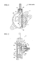
- FIGS 1, 2 show a vane pump 1 of a first embodiment according to the present invention.
- This vane pump 1 is fixed on the side surface of an engine in an automobile not shown, and is configured to generate a negative pressure in a booster of a brake control system not shown.
- This vane pump 1 includes: a housing 2 having an approximately circular pump room 2A formed thereon; a rotor 3 which is rotated at an eccentric position relative to the center of the pump room 2A by a driving force of the engine; a vane 4 rotated by the rotor 3 and for dividing the pump room 2A full-time into a plurality of spaces; and a cover 5 for covering the pump room 2A.
- an intake passage 6 located above the pump room 2A, in communication with the booster of the brake control system and for sucking in a gas from the booster is provided, and an exhaust passage 7 located below the pump room 2A, for discharging the gas sucked in from the booster is provided, respectively.
- a check valve 8 is provided in the intake passage 6, to maintain the booster in a negative pressure, especially when the engine stops.
- the rotor 3 includes a cylindrical rotor portion 3A which rotates in the pump room 2A, an outer surface of the rotor portion 3A is arranged to contact with an inner surface of the pump room 2A, the intake passage 6 is situated upstream to rotation of the rotor portion 3A, and the exhaust passage 7 is formed downstream to the rotor portion 3A.
- a groove 9 is formed in the diametrical direction, and the vane 4 is configured to move slidably along in the groove 9 in the direction perpendicular to the axial direction of the rotor 3. Then, between a hollow portion 3a formed in a central portion in the rotor portion 3A and the vane 4, a lubricating oil is arranged to flows in from an oil supply passage described below.
- caps 4a are provided, and, by rotating the caps 4a while these caps 4a are constantly brought into slidable contact with the inner surface of the pump room 2A, the pump room 2A is divided into two or three spaces full-time.
- the pump room 2A is divided by the vane 4 in the horizontal direction as shown, and further in a space on the right side in Figure 1 , the pump room is divided in the vertical direction by the rotor portion 3A, so that the pump room 2A is divided into three spaces in total.
- Figure 2 shows a cross-sectional view taken along the line II-II in Figure 1 , and in Figure 2 , a bearing 2B for supporting a shank 3B constituting the rotor 3 is formed on the right side shown of the pump room 2A of the housing 2, and the shank 3B is configured to rotate integrally with the rotor portion 3A.
- a cover 5 is provided, left side end surfaces shown of the rotor portion 3A and the vane 4 are configured to rotate slidably in contact with this cover 5, and further a right side end surface of the vane 4 is configured to rotate slidably in contact with the inner surface of the pump room 2A on the side of the bearing 2B.
- a bottom surface 9a of the groove 9 formed in the rotor 3 is formed on the side of the shank 3B slightly away from a surface at which the vane 4 slidably contacts with the pump room 2A, so that a gap is formed between the vane 4 and the bottom surface 9a.
- shank 3B projects from the bearing 2B of the housing 2 to the right side shown, at this projected position, a coupling 10 rotated by a camshaft of the engine is linked, and the rotor 3 is configured to rotate by rotation of the camshaft.
- an oil passage 11 for circulating a lubricating oil and constituting an oil supply passage is formed in its central portion, and this oil passage 11 branches at a predetermined position in the diametrical direction of the shank 3B and includes a branch passage 11a open into an outer surface of the shank 3B.
- an oil supply groove 12 constituting the oil supply passage formed to make the pump room 2A and the branch passage 11a communicate with a sliding portion along the shank 3B is formed, and in this embodiment, the oil supply groove 12 is formed on the upper side of the bearing 2B shown in Figure 2 .
- an open air passage 13 constituting an air passage is formed in the direction perpendicular to the branch passage 11a.
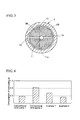
- Figure 3 shows a cross-sectional view taken along the line III-III of Figure 2 .
- an open air groove 14 for making the open air passage 13 communicate with an atmospheric air in the sliding portion along the shank 3B is formed.
- This open air groove 14 is positioned at a position rotated around the bearing 2B by 90° from the oil supply groove 12, accordingly the branch passage 11a of the oil supply passage communicates with the oil supply groove, and at the same time, the open air passage 13 communicates with the open air groove 14.
- the open air passage 13 is formed as an orifice passage, and therefore, even when the lubricating oil is pushed onto an inner wall of the oil passage 11 due to an oil supply pressure and a centrifugal force by rotation of the rotor, the lubricating oil may not easily flow outwardly from the open air passage 13.
- the orifice passage is configured as the open air passage 13 to run through the bearing 2B, but instead of this, only a certain zone of the open air passage 13 from a connecting portion with the oil passage 12 may be an orifice passage, and an outside zone from the relevant orifice passage may be a diameter expansion passage.
- the vane pump 1 gets started, concurrently, a lubricating oil is fed from the engine to the oil passage 11 formed on the rotor 3 at a predetermined pressure, and this lubricating oil is arranged to flow into the pump room 2A, when the branch passage 11a communicates with the oil supply groove 12 in the housing 2 due to rotation of the rotor 3.
- the lubricating oil which flowed into the pump room 2A flows into the hollow portion 3a in the rotor portion 3A through the gap between the bottom surface 9a of the groove 9 formed on the rotor portion 3A and the vane 4, and this lubricating oil spouts from the gap between the rotor portion 3A and the groove 9, or the gap between the vane 4 and the cover 5 into the pump room 2A to lubricate them and seal the pump room 2A, and subsequently, the lubricating oil along with the gas is discharged from the exhaust passage 7.
- the vane pump 1 of this embodiment even if the lubricating oil is pushed onto the inner wall of the oil passage 11 due to an oil supply pressure and a centrifugal force by rotation of the rotor 3, the lubricating oil may not easily flow outwardly, because the open air passage 13 is formed as the orifice passage.
- the space divided by the vane 4 on the side of the intake passage 6 stops with being at a negative pressure, but, if the opening of the branch passage 11a and the oil supply groove 12 do not coincide with each other, the lubricating oil in the oil passage 11 may not flow into the pump room 2A.
- the opening of the branch passage 11a and the oil supply groove 12 coincide with each other, at the same time, the open air passage 13 and the open air groove 14 are arranged to coincide with each other, and therefore the negative pressure in the pump room 2A is eliminated by sucking in an atmospheric air through this open air passage 13, thereby a large amount of the lubricating oil can be prevented from flowing into the pump room 2A.
- Patent Document 2 during operation of the vane pump, the lubricating oil flows outwardly through the open air passage due to an oil supply pressure and a centrifugal force by rotation of the rotor, resulting in a large amount of consumption of the lubricating oil during operation of the vane pump.
- FIG 4 shows the result of measurement of consumption of the lubricating oil, when the vane pump 1 of this embodiment (example 1), the vane pump (a conventional vane pump 1) in which the open air passage is not provided, similarly to Patent Document 1, and the vane pump (a conventional vane pump 2) in which the open air passage is in constant communication with the oil supply passage, similarly to Patent Document 2, each vane pump is operated for a certain time period.
- the consumption of the lubricating oil of the example 1 is larger than that of the conventional vane pump 1, but in the example 1, an amount of the lubricating oil flowing into the pump room 2A can be controlled to be less than that of the conventional vane pump 1 and the damage of the vane 4 described above can be effectively prevented.
- the example 1 when the example 1 is compared to the conventional vane pump 2, their amounts of the lubricating oil flowing into the pump room 2A are equivalent, but the consumption of the lubricating oil of the example 1 can be controlled to be less than that of the conventional vane pump 2, and also, performance deterioration of the vane pump 1 at a low supply pressure of the lubricating oil, as described above, can be effectively prevented.
- the oil supply groove 12 is positioned above the bearing 2B
- the open air groove 14 is positioned at a position rotated around the bearing 2B by 90° from the oil supply groove
- the branch passage 11a and the open air passage 13 are oriented in the direction perpendicular to the diametrical direction of the shank 3B, but on the condition that a timing at which the branch passage 11a and the oil supply groove 12 coincide with each other and a timing at which the open air groove 13 and the open air groove 14 coincide with each other would occur at the same time
- the oil supply groove 12 and the open air groove 14 may be formed at a different position, and correspondingly to it, the branch passage 11a and the open air passage 13 may be oriented in a different direction.
- a vane pump 1 shown here similarly to the first embodiment described above, includes a branch passage 11a which branches from an oil passage 11 provided in the central portion of a shank 3B of a rotor 3, and like components as those of the first embodiment described above, such as the branch passage 11a, will be described using like symbols hereinafter.
- Figure 5 shows with a vane being omitted.
- an open air passage 13 and an open air groove 14 in a bearing 2B of a housing 2 similar to the first embodiment described above are not provided.
- an open air passage 21 of this embodiment is formed in the same direction as the axial direction of the rotor 3, and further formed to directly communicate with the branch passage 11a formed in the diametrical direction.
- a check valve 22 is provided, a lubricating oil which flowed from an oil passage 11a into the open air passage 21 is arranged not to flow outwardly through the open air passage 21, and further in a coupling 10, a runout 10a is formed so that the open air passage 21 is not blocked.
- the vane pump 1 having the configuration as described above will be described hereinafter. Similarly to the vane pump 1 of the embodiment described above, the vane pump 1 is operated due to operation of an engine and a gas is sucked in from a booster through an intake passage 6.
- the check valve 22 prevents the lubricating oil which flowed into the open air passage 21 from flowing outwardly.
- the engine stops, and, similarly to the first embodiment, when the branch passage 11a coincides with the oil supply groove 12 in position, the lubricating oil is not fed at a predetermined pressure and further owing to a differential pressure between a pressure in the pump room 2A and an atmospheric pressure, a pressure in the oil passage 11 also becomes negative, then the check valve is opened to suck an atmospheric air into the pump room 2A, thereby a negative pressure in the pump room 2A is eliminated.
- the lubricating oil can be prevented from flowing into the pump room 2A in large quantities and a damage of a vane 4, as described above, can be avoided.
- the amount of consumption of the lubricating oil can be equivalent to that of the conventional vane pump 1, and further the amount of the lubricating oil which flows into the pump room 2A at stop of the engine can be also equivalent to that of the conventional vane pump 2.
Landscapes
- Engineering & Computer Science (AREA)
- Mechanical Engineering (AREA)
- General Engineering & Computer Science (AREA)
- Rotary Pumps (AREA)
- Applications Or Details Of Rotary Compressors (AREA)
Applications Claiming Priority (2)
| Application Number | Priority Date | Filing Date | Title |
|---|---|---|---|
| JP2005039641A JP3874300B2 (ja) | 2005-02-16 | 2005-02-16 | ベーンポンプ |
| EP06712697.9A EP1850007B1 (de) | 2005-02-16 | 2006-01-31 | Flügelzellenpumpe |
Related Parent Applications (2)
| Application Number | Title | Priority Date | Filing Date |
|---|---|---|---|
| EP06712697.9 Division | 2006-01-31 | ||
| EP06712697.9A Division-Into EP1850007B1 (de) | 2005-02-16 | 2006-01-31 | Flügelzellenpumpe |
Publications (1)
| Publication Number | Publication Date |
|---|---|
| EP2634431A1 true EP2634431A1 (de) | 2013-09-04 |
Family
ID=36916314
Family Applications (2)
| Application Number | Title | Priority Date | Filing Date |
|---|---|---|---|
| EP06712697.9A Expired - Lifetime EP1850007B1 (de) | 2005-02-16 | 2006-01-31 | Flügelzellenpumpe |
| EP13167793.2A Withdrawn EP2634431A1 (de) | 2005-02-16 | 2006-01-31 | Flügelzellenpumpe |
Family Applications Before (1)
| Application Number | Title | Priority Date | Filing Date |
|---|---|---|---|
| EP06712697.9A Expired - Lifetime EP1850007B1 (de) | 2005-02-16 | 2006-01-31 | Flügelzellenpumpe |
Country Status (8)
| Country | Link |
|---|---|
| US (2) | US7896631B2 (de) |
| EP (2) | EP1850007B1 (de) |
| JP (1) | JP3874300B2 (de) |
| KR (1) | KR100898950B1 (de) |
| CN (1) | CN101120174B (de) |
| PL (1) | PL1850007T3 (de) |
| RU (1) | RU2368809C2 (de) |
| WO (1) | WO2006087903A1 (de) |
Families Citing this family (25)
| Publication number | Priority date | Publication date | Assignee | Title |
|---|---|---|---|---|
| JP3874300B2 (ja) * | 2005-02-16 | 2007-01-31 | 大豊工業株式会社 | ベーンポンプ |
| GB0607198D0 (en) * | 2006-04-10 | 2006-05-17 | Wabco Automotive Uk Ltd | Improved vacuum pump |
| JP4165608B1 (ja) * | 2007-06-26 | 2008-10-15 | 大豊工業株式会社 | ベーン式バキュームポンプ |
| KR20110019287A (ko) * | 2009-08-19 | 2011-02-25 | 주식회사 팬택 | 무선통신 시스템에서 정보 전송방법 및 그 전송장치 |
| EP2530325B1 (de) * | 2010-01-29 | 2018-10-17 | Ulvac Kiko, Inc. | Pumpe |
| JP5447149B2 (ja) | 2010-04-27 | 2014-03-19 | 大豊工業株式会社 | ベーンポンプ |
| JP5589532B2 (ja) | 2010-04-27 | 2014-09-17 | 大豊工業株式会社 | ベーンポンプ |
| DE102010044898A1 (de) * | 2010-09-09 | 2012-03-15 | Schwäbische Hüttenwerke Automotive GmbH | Vakuumpumpe mit Lüftungseinrichtung |
| JP2012067729A (ja) * | 2010-09-27 | 2012-04-05 | Taiho Kogyo Co Ltd | ベーンポンプ |
| JP2012067730A (ja) * | 2010-09-27 | 2012-04-05 | Taiho Kogyo Co Ltd | ベーンポンプ |
| EP2559903A1 (de) | 2011-08-17 | 2013-02-20 | Wabco Automotive UK Limited | Verbesserte Vakuumpumpe |
| EP2677118B1 (de) * | 2012-06-20 | 2018-03-28 | Pierburg Pump Technology GmbH | Volumetrische Automobilvakuumpumpe |
| CN104755763B (zh) * | 2012-10-22 | 2017-08-15 | 麦格纳动力系巴德霍姆堡有限责任公司 | 泵 |
| ITTO20121157A1 (it) * | 2012-12-27 | 2014-06-28 | Vhit Spa | Sistema di lubrificazione per una pompa per vuoto rotativa. |
| US9212662B2 (en) * | 2013-04-29 | 2015-12-15 | Ford Global Technologies, Llc | Check valve for an engine vacuum pump |
| JP6305708B2 (ja) | 2013-08-22 | 2018-04-04 | 株式会社ミクニ | バキュームポンプ機構 |
| ES2612232T3 (es) | 2014-06-05 | 2017-05-12 | Wabco Europe Bvba | Bomba de vacío y sistema de una bomba de vacío y un motor |
| WO2016108171A1 (en) * | 2014-12-29 | 2016-07-07 | Vhit S.P.A. | Rotary fluid pump |
| JP6317297B2 (ja) * | 2015-07-22 | 2018-04-25 | トヨタ自動車株式会社 | 内燃機関 |
| JP6311671B2 (ja) | 2015-07-22 | 2018-04-18 | トヨタ自動車株式会社 | 内燃機関 |
| CN107923400A (zh) * | 2015-08-19 | 2018-04-17 | 皮尔伯格泵技术有限责任公司 | 润滑的汽车真空泵 |
| CN105526171A (zh) * | 2016-02-05 | 2016-04-27 | 无锡明治泵业有限公司 | 一种汽车真空泵降低泵腔内积油量的结构 |
| JP6382877B2 (ja) * | 2016-03-24 | 2018-08-29 | 大豊工業株式会社 | ベーンポンプ |
| JP6534647B2 (ja) * | 2016-11-03 | 2019-06-26 | 大豊工業株式会社 | ベーンポンプ |
| CN109737059B (zh) * | 2019-01-03 | 2020-05-22 | 上海日炙机械制造有限公司 | 一种真空泵转子及其加工工艺 |
Citations (5)
| Publication number | Priority date | Publication date | Assignee | Title |
|---|---|---|---|---|
| JPH07189971A (ja) * | 1993-12-27 | 1995-07-28 | Seiko Seiki Co Ltd | 気体圧縮機 |
| JP3107906B2 (ja) | 1991-05-29 | 2000-11-13 | ルーク アウトモービルテヒニーク ゲゼルシャフト ミット ベシュレンクテル ハフツング ウント コンパニー コマンディトゲゼルシャフト | ベーン型真空ポンプ |
| EP1108892A2 (de) * | 1999-12-18 | 2001-06-20 | Bayerische Motoren Werke Aktiengesellschaft | Flügelzellenvakuumpumpe |
| WO2002030726A1 (de) * | 2000-10-11 | 2002-04-18 | Luk Automobilitechnik Gmbh & Co. Kg | Vakuumpumpe für einen servoantrieb in einem kraftfahrzeug |
| JP2003239882A (ja) | 2002-02-15 | 2003-08-27 | Toyota Motor Corp | 負圧発生源の潤滑構造及び給油パイプ |
Family Cites Families (20)
| Publication number | Priority date | Publication date | Assignee | Title |
|---|---|---|---|---|
| JPS5214491Y2 (de) * | 1973-04-02 | 1977-04-01 | ||
| JPS52123317U (de) * | 1976-03-16 | 1977-09-20 | ||
| JPS5819379B2 (ja) | 1976-04-08 | 1983-04-18 | 三菱重工業株式会社 | 有機粘結剤を用いた廃鋳物砂の再生方法 |
| DE2952401A1 (de) * | 1978-07-28 | 1981-06-25 | Barmag Barmer Maschinenfabrik Ag, 5630 Remscheid | Druckoelschmierung fuer eine vakuumpumpe, insbesondere fluegelzellenvakuumpumpe |
| AU5180279A (en) * | 1978-10-27 | 1980-05-01 | Dynavac Pty. Ltd. | Vacuum pump inlet valve |
| US4276005A (en) * | 1979-04-26 | 1981-06-30 | Varian Associates, Inc. | Oil flow metering structure for oil sealed mechanical vacuum vane pump |
| US4772185A (en) * | 1985-11-27 | 1988-09-20 | Barmag Ag | Rotary vane pump having a plurality of inlet and outlet slots in a rotating sleeve |
| JPH02218885A (ja) * | 1989-02-21 | 1990-08-31 | Toyoda Mach Works Ltd | バキュームポンプ |
| JP2782858B2 (ja) * | 1989-10-31 | 1998-08-06 | 松下電器産業株式会社 | スクロール気体圧縮機 |
| JP2861186B2 (ja) * | 1990-01-26 | 1999-02-24 | 株式会社デンソー | 偏心型真空ポンプの油量制御機構 |
| JPH1162864A (ja) * | 1997-08-22 | 1999-03-05 | Sanwa Seiki Co Ltd | 自動車用真空ポンプ |
| US6190149B1 (en) * | 1999-04-19 | 2001-02-20 | Stokes Vacuum Inc. | Vacuum pump oil distribution system with integral oil pump |
| CN2532276Y (zh) * | 2001-10-12 | 2003-01-22 | 常玲琪 | 一种高速滑片真空泵 |
| JP2004011421A (ja) * | 2002-06-03 | 2004-01-15 | Toyoda Mach Works Ltd | ベーン式バキュームポンプ |
| JP2004263690A (ja) * | 2003-02-13 | 2004-09-24 | Aisan Ind Co Ltd | ベーン式バキュームポンプ |
| CN2617957Y (zh) * | 2003-05-23 | 2004-05-26 | 山东博山齐鲁油泵厂 | 叶片式加油车油泵 |
| RU2266430C2 (ru) * | 2003-11-26 | 2005-12-20 | Открытое акционерное общество Научно-производственное объединение "Искра" | Агрегат компрессорный ротационно-пластинчатый |
| JP4733356B2 (ja) * | 2004-03-10 | 2011-07-27 | トヨタ自動車株式会社 | 気体用ベーンポンプおよびその運転方法 |
| JP2006118424A (ja) * | 2004-10-21 | 2006-05-11 | Toyota Motor Corp | バキュームポンプ |
| JP3874300B2 (ja) * | 2005-02-16 | 2007-01-31 | 大豊工業株式会社 | ベーンポンプ |
-
2005
- 2005-02-16 JP JP2005039641A patent/JP3874300B2/ja not_active Expired - Fee Related
-
2006
- 2006-01-31 KR KR1020077018645A patent/KR100898950B1/ko not_active Expired - Fee Related
- 2006-01-31 CN CN2006800051416A patent/CN101120174B/zh not_active Expired - Fee Related
- 2006-01-31 EP EP06712697.9A patent/EP1850007B1/de not_active Expired - Lifetime
- 2006-01-31 WO PCT/JP2006/301554 patent/WO2006087903A1/ja not_active Ceased
- 2006-01-31 PL PL06712697T patent/PL1850007T3/pl unknown
- 2006-01-31 EP EP13167793.2A patent/EP2634431A1/de not_active Withdrawn
- 2006-01-31 US US11/884,216 patent/US7896631B2/en active Active
- 2006-01-31 RU RU2007134431/06A patent/RU2368809C2/ru not_active IP Right Cessation
-
2010
- 2010-10-05 US US12/924,778 patent/US8382462B2/en not_active Expired - Fee Related
Patent Citations (5)
| Publication number | Priority date | Publication date | Assignee | Title |
|---|---|---|---|---|
| JP3107906B2 (ja) | 1991-05-29 | 2000-11-13 | ルーク アウトモービルテヒニーク ゲゼルシャフト ミット ベシュレンクテル ハフツング ウント コンパニー コマンディトゲゼルシャフト | ベーン型真空ポンプ |
| JPH07189971A (ja) * | 1993-12-27 | 1995-07-28 | Seiko Seiki Co Ltd | 気体圧縮機 |
| EP1108892A2 (de) * | 1999-12-18 | 2001-06-20 | Bayerische Motoren Werke Aktiengesellschaft | Flügelzellenvakuumpumpe |
| WO2002030726A1 (de) * | 2000-10-11 | 2002-04-18 | Luk Automobilitechnik Gmbh & Co. Kg | Vakuumpumpe für einen servoantrieb in einem kraftfahrzeug |
| JP2003239882A (ja) | 2002-02-15 | 2003-08-27 | Toyota Motor Corp | 負圧発生源の潤滑構造及び給油パイプ |
Also Published As
| Publication number | Publication date |
|---|---|
| CN101120174A (zh) | 2008-02-06 |
| CN101120174B (zh) | 2010-12-01 |
| RU2007134431A (ru) | 2009-03-27 |
| JP3874300B2 (ja) | 2007-01-31 |
| US7896631B2 (en) | 2011-03-01 |
| EP1850007B1 (de) | 2014-05-21 |
| WO2006087903A1 (ja) | 2006-08-24 |
| US8382462B2 (en) | 2013-02-26 |
| KR100898950B1 (ko) | 2009-05-25 |
| RU2368809C2 (ru) | 2009-09-27 |
| EP1850007A1 (de) | 2007-10-31 |
| EP1850007A4 (de) | 2012-11-14 |
| JP2006226164A (ja) | 2006-08-31 |
| US20080101975A1 (en) | 2008-05-01 |
| US20110064598A1 (en) | 2011-03-17 |
| PL1850007T3 (pl) | 2014-10-31 |
| KR20070100794A (ko) | 2007-10-11 |
Similar Documents
| Publication | Publication Date | Title |
|---|---|---|
| US8382462B2 (en) | Vane pump with circulating oil supply passage | |
| US7588433B2 (en) | Vane pump | |
| EP2397696B1 (de) | Flügelzellenpumpe | |
| CN103807166B (zh) | 涡旋压缩机 | |
| JP4733356B2 (ja) | 気体用ベーンポンプおよびその運転方法 | |
| EP2602487B1 (de) | Flügelzellenpumpe | |
| JP2016156336A (ja) | ベーン型圧縮機 | |
| JP2006118424A (ja) | バキュームポンプ | |
| JP2001140781A (ja) | 気体圧縮機 | |
| KR20220100707A (ko) | 슬라이딩 부품 | |
| JP2001165082A (ja) | スライディングベーン式圧縮機 | |
| CN107923400A (zh) | 润滑的汽车真空泵 | |
| EP3303843B1 (de) | Kraftfahrzeugvakuumpumpe |
Legal Events
| Date | Code | Title | Description |
|---|---|---|---|
| PUAI | Public reference made under article 153(3) epc to a published international application that has entered the european phase |
Free format text: ORIGINAL CODE: 0009012 |
|
| AC | Divisional application: reference to earlier application |
Ref document number: 1850007 Country of ref document: EP Kind code of ref document: P |
|
| AK | Designated contracting states |
Kind code of ref document: A1 Designated state(s): AT BE BG CH CY CZ DE DK EE ES FI FR GB GR HU IE IS IT LI LT LU LV MC NL PL PT RO SE SI SK TR |
|
| 17P | Request for examination filed |
Effective date: 20140224 |
|
| RBV | Designated contracting states (corrected) |
Designated state(s): AT BE BG CH CY CZ DE DK EE ES FI FR GB GR HU IE IS IT LI LT LU LV MC NL PL PT RO SE SI SK TR |
|
| STAA | Information on the status of an ep patent application or granted ep patent |
Free format text: STATUS: THE APPLICATION IS DEEMED TO BE WITHDRAWN |
|
| 18D | Application deemed to be withdrawn |
Effective date: 20160802 |