EP2634438A2 - Vorrichtung zur Beseitigung des Spiels in einem Loch, entsprechendes Türscharnier und Montageverfahren - Google Patents
Vorrichtung zur Beseitigung des Spiels in einem Loch, entsprechendes Türscharnier und Montageverfahren Download PDFInfo
- Publication number
- EP2634438A2 EP2634438A2 EP12178214.8A EP12178214A EP2634438A2 EP 2634438 A2 EP2634438 A2 EP 2634438A2 EP 12178214 A EP12178214 A EP 12178214A EP 2634438 A2 EP2634438 A2 EP 2634438A2
- Authority
- EP
- European Patent Office
- Prior art keywords
- sleeve
- receiving sleeve
- hole
- receiving
- clearance
- Prior art date
- Legal status (The legal status is an assumption and is not a legal conclusion. Google has not performed a legal analysis and makes no representation as to the accuracy of the status listed.)
- Withdrawn
Links
- 238000000034 method Methods 0.000 title claims abstract description 11
- 125000006850 spacer group Chemical group 0.000 claims abstract description 54
- 230000000295 complement effect Effects 0.000 claims abstract description 13
- 230000000903 blocking effect Effects 0.000 claims description 10
- 230000036961 partial effect Effects 0.000 claims description 8
- 230000005540 biological transmission Effects 0.000 description 8
- 238000004519 manufacturing process Methods 0.000 description 3
- 230000003247 decreasing effect Effects 0.000 description 1
- 230000000670 limiting effect Effects 0.000 description 1
- 239000000463 material Substances 0.000 description 1
- 230000002829 reductive effect Effects 0.000 description 1
- 230000000717 retained effect Effects 0.000 description 1
- 239000007787 solid Substances 0.000 description 1
Images



Classifications
-
- F—MECHANICAL ENGINEERING; LIGHTING; HEATING; WEAPONS; BLASTING
- F16—ENGINEERING ELEMENTS AND UNITS; GENERAL MEASURES FOR PRODUCING AND MAINTAINING EFFECTIVE FUNCTIONING OF MACHINES OR INSTALLATIONS; THERMAL INSULATION IN GENERAL
- F16B—DEVICES FOR FASTENING OR SECURING CONSTRUCTIONAL ELEMENTS OR MACHINE PARTS TOGETHER, e.g. NAILS, BOLTS, CIRCLIPS, CLAMPS, CLIPS OR WEDGES; JOINTS OR JOINTING
- F16B7/00—Connections of rods or tubes, e.g. of non-circular section, mutually, including resilient connections
- F16B7/02—Connections of rods or tubes, e.g. of non-circular section, mutually, including resilient connections with conical parts
-
- E—FIXED CONSTRUCTIONS
- E05—LOCKS; KEYS; WINDOW OR DOOR FITTINGS; SAFES
- E05D—HINGES OR SUSPENSION DEVICES FOR DOORS, WINDOWS OR WINGS
- E05D5/00—Construction of single parts, e.g. the parts for attachment
- E05D5/02—Parts for attachment, e.g. flaps
- E05D5/0207—Parts for attachment, e.g. flaps for attachment to vehicles
-
- E—FIXED CONSTRUCTIONS
- E05—LOCKS; KEYS; WINDOW OR DOOR FITTINGS; SAFES
- E05D—HINGES OR SUSPENSION DEVICES FOR DOORS, WINDOWS OR WINGS
- E05D5/00—Construction of single parts, e.g. the parts for attachment
- E05D5/02—Parts for attachment, e.g. flaps
- E05D5/06—Bent flaps
- E05D5/062—Bent flaps specially adapted for vehicles
-
- E—FIXED CONSTRUCTIONS
- E05—LOCKS; KEYS; WINDOW OR DOOR FITTINGS; SAFES
- E05F—DEVICES FOR MOVING WINGS INTO OPEN OR CLOSED POSITION; CHECKS FOR WINGS; WING FITTINGS NOT OTHERWISE PROVIDED FOR, CONCERNED WITH THE FUNCTIONING OF THE WING
- E05F15/00—Power-operated mechanisms for wings
- E05F15/60—Power-operated mechanisms for wings using electrical actuators
- E05F15/603—Power-operated mechanisms for wings using electrical actuators using rotary electromotors
- E05F15/611—Power-operated mechanisms for wings using electrical actuators using rotary electromotors for swinging wings
- E05F15/614—Power-operated mechanisms for wings using electrical actuators using rotary electromotors for swinging wings operated by meshing gear wheels, one of which being mounted at the wing pivot axis; operated by a motor acting directly on the wing pivot axis
-
- E—FIXED CONSTRUCTIONS
- E05—LOCKS; KEYS; WINDOW OR DOOR FITTINGS; SAFES
- E05F—DEVICES FOR MOVING WINGS INTO OPEN OR CLOSED POSITION; CHECKS FOR WINGS; WING FITTINGS NOT OTHERWISE PROVIDED FOR, CONCERNED WITH THE FUNCTIONING OF THE WING
- E05F15/00—Power-operated mechanisms for wings
- E05F15/60—Power-operated mechanisms for wings using electrical actuators
- E05F15/603—Power-operated mechanisms for wings using electrical actuators using rotary electromotors
- E05F15/611—Power-operated mechanisms for wings using electrical actuators using rotary electromotors for swinging wings
- E05F15/63—Power-operated mechanisms for wings using electrical actuators using rotary electromotors for swinging wings operated by swinging arms
-
- F—MECHANICAL ENGINEERING; LIGHTING; HEATING; WEAPONS; BLASTING
- F16—ENGINEERING ELEMENTS AND UNITS; GENERAL MEASURES FOR PRODUCING AND MAINTAINING EFFECTIVE FUNCTIONING OF MACHINES OR INSTALLATIONS; THERMAL INSULATION IN GENERAL
- F16B—DEVICES FOR FASTENING OR SECURING CONSTRUCTIONAL ELEMENTS OR MACHINE PARTS TOGETHER, e.g. NAILS, BOLTS, CIRCLIPS, CLAMPS, CLIPS OR WEDGES; JOINTS OR JOINTING
- F16B13/00—Dowels or other devices fastened in walls or the like by inserting them in holes made therein for that purpose
- F16B13/04—Dowels or other devices fastened in walls or the like by inserting them in holes made therein for that purpose with parts gripping in the hole or behind the reverse side of the wall after inserting from the front
- F16B13/06—Dowels or other devices fastened in walls or the like by inserting them in holes made therein for that purpose with parts gripping in the hole or behind the reverse side of the wall after inserting from the front combined with expanding sleeve
- F16B13/063—Dowels or other devices fastened in walls or the like by inserting them in holes made therein for that purpose with parts gripping in the hole or behind the reverse side of the wall after inserting from the front combined with expanding sleeve by the use of an expander
- F16B13/065—Dowels or other devices fastened in walls or the like by inserting them in holes made therein for that purpose with parts gripping in the hole or behind the reverse side of the wall after inserting from the front combined with expanding sleeve by the use of an expander fastened by extracting the screw, nail or the like
-
- F—MECHANICAL ENGINEERING; LIGHTING; HEATING; WEAPONS; BLASTING
- F16—ENGINEERING ELEMENTS AND UNITS; GENERAL MEASURES FOR PRODUCING AND MAINTAINING EFFECTIVE FUNCTIONING OF MACHINES OR INSTALLATIONS; THERMAL INSULATION IN GENERAL
- F16B—DEVICES FOR FASTENING OR SECURING CONSTRUCTIONAL ELEMENTS OR MACHINE PARTS TOGETHER, e.g. NAILS, BOLTS, CIRCLIPS, CLAMPS, CLIPS OR WEDGES; JOINTS OR JOINTING
- F16B13/00—Dowels or other devices fastened in walls or the like by inserting them in holes made therein for that purpose
- F16B13/04—Dowels or other devices fastened in walls or the like by inserting them in holes made therein for that purpose with parts gripping in the hole or behind the reverse side of the wall after inserting from the front
- F16B13/06—Dowels or other devices fastened in walls or the like by inserting them in holes made therein for that purpose with parts gripping in the hole or behind the reverse side of the wall after inserting from the front combined with expanding sleeve
- F16B13/063—Dowels or other devices fastened in walls or the like by inserting them in holes made therein for that purpose with parts gripping in the hole or behind the reverse side of the wall after inserting from the front combined with expanding sleeve by the use of an expander
- F16B13/066—Dowels or other devices fastened in walls or the like by inserting them in holes made therein for that purpose with parts gripping in the hole or behind the reverse side of the wall after inserting from the front combined with expanding sleeve by the use of an expander fastened by extracting a separate expander-part, actuated by the screw, nail or the like
-
- E—FIXED CONSTRUCTIONS
- E05—LOCKS; KEYS; WINDOW OR DOOR FITTINGS; SAFES
- E05Y—INDEXING SCHEME ASSOCIATED WITH SUBCLASSES E05D AND E05F, RELATING TO CONSTRUCTION ELEMENTS, ELECTRIC CONTROL, POWER SUPPLY, POWER SIGNAL OR TRANSMISSION, USER INTERFACES, MOUNTING OR COUPLING, DETAILS, ACCESSORIES, AUXILIARY OPERATIONS NOT OTHERWISE PROVIDED FOR, APPLICATION THEREOF
- E05Y2900/00—Application of doors, windows, wings or fittings thereof
- E05Y2900/50—Application of doors, windows, wings or fittings thereof for vehicles
- E05Y2900/53—Type of wing
- E05Y2900/546—Tailboards, tailgates or sideboards opening upwards
Definitions
- the invention relates to a device for eliminating a clearance in a hole of an element.
- the element may be a hinge belonging to a pivotable door of an automotive vehicle.
- the vehicle door may be a side door or a tailgate or the lid for closing the engine compartment or the flap for closing a roof opening in a vehicle.
- the hinge is thereafter named door hinge.
- This invention also relates to such a door hinge comprising a hole in which the device for eliminating a clearance is mounted.
- the invention also relates to the method for assembling the device for eliminating a clearance in a hole of an element, such as the door hinge.
- two modular drive units for actuating the tailgate are generally connected to two door hinges.
- a modular drive unit comprises in a known manner a motor, a gear assembly and transmission means connected to the door hinge.
- a lever is on one end screwed to a moving part of the hinge. And this lever may have a bushing put on a pin or axis on the hinge.
- the modular drive unit may also be tightened with the door hinge trough a device mounted in a hole of the hinge. To that end, such a device traditionally has tightening means such as a bolt with a nut.
- the hole of the door hinge is an oval hole and for eliminating the clearance between the bolt and the hole, an eccentric bolt is used.
- the eccentric bolt is turned in the oval hole until it locks, meaning the clearance is eliminated. And then the nut may be tightened.
- a solution consists in replacing the eccentric bolt by an assembly of a conical bolt and a spacer with split sleeve in a single piece. Indeed when tightening the conical pin of the bolt causes the sleeve to bend outwards.
- Another problem of this solution is that the load which is transmitted is concentrated in one point.
- the object of the present invention is thus to overcome these drawbacks of the prior art.
- one subject of the invention is to provide a device for eliminating a clearance in the hole of an element in a sustainable manner while improving the load transmission.
- a device for eliminating a clearance in a hole of an element comprising:
- the receiving sleeve expands uniformly in a parallel way of the mounting hole and therefore the form fit to the mounting hole as well as the transmission of the load is improved.
- the receiving sleeve and the wall defining the hole are in contact by a line. Therefore, there is no more punctual contact. Thus the connection is more robust.
- the effort in assembly is less than the eccentric bolt concept as only tightening is required without needing an adjustment of the eccentric bolt in addition.
- the device according to the invention may also comprise one or more of the following features, taken separately or in combination:
- the invention also related to a door hinge for a vehicle including a hole for fixing said door hinge to a modular drive unit of a vehicle door and a device for eliminating the clearance in the hole of said door hinge comprising:
- the invention relates to the method for assembling the device as described above in a hole of an element, comprising the steps of:
- reference 1 indicates a device 1 for eliminating a clearance in a hole of an element in which the device 1 is mounted.
- the invention is particularly aimed at eliminating a clearance in a hinge 3 of a vehicle door.
- Said hinge 3 is thereafter named door hinge 3.
- vehicle door is understood quite generally to mean a pivotable part for closing a vehicle opening.
- the vehicle door may therefore involve an element selected in the list consisting of a side door, a tailgate, the lid for closing the engine compartment and the flap for closing a roof opening in a vehicle.
- the following description refers to a tailgate which can be pivoted via a door hinge 3.
- Figure 2 shows partially the roof 5 and a pillar 7 of a corresponding vehicle comprising such a door hinge 3 for pivoting the tailgate (not illustrated).
- the vehicle door by instance the tailgate, can be actuated by a modular drive unit 9 connected to the door hinge 3.
- a modular drive unit 9 connected to the door hinge 3.
- two modular drive units 9 are respectfully connected to one of two door hinges 3.
- the modular drive unit 9 is arranged on and fastened to a roof support 11.
- Such a modular drive unit 9 is more visible on figures 3 and 4 .
- a bracket 13 may be provided for fastening said modular drive unit 9 to the roof support 11.
- This modular drive unit 9 comprises an electric motor 15.
- the modular drive unit 9 also comprises a tubular housing 17 receiving a gear assembly connected to the electric motor 15, and a transmission means 19 connected on one hand to the gear assembly and on the other hand to the door hinge 3.
- the transmission means 19 may comprise a lever 19 arranged between the modular drive unit 9 and the door hinge 3.
- the door hinge 3 may comprise a first fixed hinge body 3a and a second moving hinge body 3b.
- the first fixed hinge body 3a is fixed to the roof support 11 and the second moving hinge body 3b is mounted in a pivotable manner.
- the lever 19 may be fastened to one end 19a to the second moving hinge body 3b via fixation means 21 ( figures 1 and 4 ). For example, this end 19a may be screwed to the second moving hinge body 3b.
- the lever 19 is also fastened to its other end 19b to the first fixed hinge body 3a and to the modular drive unit 9.
- the first hinge body 3a includes a hinge axis 23 attached to the transmission means 19 of the modular drive unit 9, for example to end 19b of the lever 19 opposed to end 19a connected to the second moving hinge body 3b.
- the hinge axis 23 may be connected to the lever 19 via a bushing 25 ( figure 4 ).
- the second hinge body 3b is mounted in a manner such that it can pivot about the hinge axis 23 of the first hinge body 3a ( figure 3 ).
- the first hinge body 3a is further maintained with the modular drive unit 9 via the device for eliminating a clearance 1 which is mounted in a hole of the first hinge body 3a.
- This hole may be an oval hole.
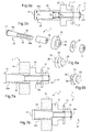
- a first embodiment of the device 1 for eliminating the clearance is shown on figures 5a to 7b .
- Such a device 1 comprises :
- the tightening means 27 include a bolt 29 and a nut 31, the first part being a bolt 29 and the second part being a nut 31.
- the bolt 29 is a threaded bolt as it can be seen on figure 5b .
- the bolt 29 is inserted in the cylindrical receiving sleeve 33.
- the bolt 29 is then inserted in the spacer 35.
- the bolt 29 includes two bolt parts : a front portion 29a and a pin 29b, particularly a threaded pin 29b.
- the front portion 29a is inserted in the receiving sleeve 33 and the pin 29b is inserted in the spacer 35 and the nut 31. Moreover, the end of the pin 29b protrudes from said device 1.
- the bolt 29 is at least partially provided with a substantially conical outer shape. That means at least one part of the bolt 29 has a substantially conical outer shape.
- the front portion 29a is substantially conical and the pin 29b is substantially cylindrical.
- the conical front portion 29a has a progressively decreasing diameter with the largest diameter D 1 at the end of the bolt 29 opposed to the protruded end of the pin 29b and the nut 31.
- the smallest diameter D 2 of the front portion 29a is at the end of the front portion 29a opposed to the largest diameter D 1 .
- the pin 29b of the bolt 29, substantially cylindrical, has a diameter D 3 smaller than the smallest diameter D 2 of the front portion 29a of the bolt 29.
- the receiving sleeve 33 has an inner shape substantially conical corresponding to the substantially conical outer shape of the front portion 29a of the bolt 29.
- the conical outer shape of the front portion 29a of the bolt 29 correlates to the conical inner shape of the cylindrical receiving sleeve 33.
- This receiving sleeve 33 may be a single piece.
- the receiving sleeve 33 is a slotted sleeve or slit sleeve 33 with a longitudinal slot or slit 34 visible on figure 5b . Due to this slot 34 the diameter of the slotted sleeve 33 can expand when the bolt 29 is rotating and thus fit the clearance in the hole of the door hinge 3. When tightening, it is the plain part of the receiving sleeve 33 that pushes to fit the clearance in the receiving hole.
- the conical bolt 29 and the conical inner shape of the slotted sleeve 33 enables the slotted sleeve 33 to adapt a wide range of exterior diameters when the conical bolt 29 is moved in axial direction whereas the slotted sleeve 33 keeps a cylindrical outer shape.
- the receiving sleeve 33 and the spacer 35 do not form a single piece but two distinct elements assembled together during the assembly of the device.
- the spacer 35 and the receiving sleeve 33 are made in two parts.
- the spacer 35 may be made in a material different from the one of the receiving sleeve 33.
- the spacer is in particular arranged between the first fixed hinge body 3a and the modular drive unit 9.
- the spacer 35 may have a first part substantially cylindrical and an extension also substantially cylindrical but with a smaller diameter. Such an extension fits into a corresponding hole in the modular drive unit 9 ( figure 3 ). The spacer 35 is thus arrested in the modular drive unit 9.
- the device 1 further comprises a washer 37 interposed between the spacer 35 and the nut 31.
- the washer 37 is destined to be interposed between the modular drive unit 9 and the nut 31.
- the washer 37 and the nut 31 are on the end of the pin 29b of the bolt 29 to tighten the bolt 29.
- the bolt 29 may be provided with two opposite areas 39 which are substantially flat. Only one flat area 39 is clearly visible on figure 5b . These flat opposite areas 39 are intended for being inserted in the spacer 35 and avoiding the rotation of the bolt 29.
- the flat areas 39 are provided on the pin 29b of the bolt 29.
- the pin 29b of the bolt 29 is flattened on two opposite sides to fit through a related hole in the spacer 35. As visible on figure 5b , the spacer 35 may have corresponding flattened areas 40.
- the device 1 may comprise means for blocking the receiving sleeve 33 in rotation.
- the receiving sleeve 33 and the spacer 35 are connected in a form-blocking manner in order to prevent from the rotation of the receiving sleeve 33.
- the form-blocking connection may be obtained by at least one rib 36, 36' engaging in a complementary notch.
- the rib or ribs 36 may be formed on the spacer 35 and thus engage an associated notch on the receiving sleeve 33 ( figure 6a ) or may be formed on the receiving sleeve 33 and thus engage an associated notch on the spacer 35 ( figure 6b ).
- the bolt 29 is provided with a head 41.
- the front portion 29a of the bolt extends from the head 41.
- the bolt head 41 is thus opposed to the protruded end of the pin 29b and the nut 31.
- the bolt 29 is rotated until it locks. Then the nut 31 is tightened.
- the bolt 29 During rotation of the bolt 29 while being inserted into the slotted sleeve 33, the bolt 29, in particular the conical part 29a of the bolt 29, increases the diameter of the slotted sleeve 33. As the diameter increases all along the length of the slotted sleeve 33 the contact face of the slotted sleeve 33 with the hole wall of the door hinge 3 is large and the clearance is eliminated.
- the bolt 29 holds together the assembly by the pressure exerted by its head 41 at one end and the pressure of the nut 31 that screws onto the other end ( figure 7b ).
- the method for assembling such a device 1 in a hole by instance of the door hinge 3 comprises a first step in which the bolt 29 is partially inserted in the receiving sleeve 33 which is then introduced into the hole.
- the spacer 35 and the washer 37, in this order, are put at one end of the receiving sleeve 33.
- the nut 31 is then screwed onto the bolt 29.
- the bolt 29 is introduced further in the receiving sleeve 33 by rotation until the outside surface of the receiving sleeve 33 comes in contact with the inside wall of the door hinge 3 delimiting the comprising hole.
- the bolt 29 is thus an adjusting bolt for eliminating the clearance in the comprising hole.
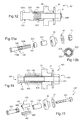
- a second embodiment of a device 101 for eliminating a clearance is represented on figures 8 and 9 .
- This second embodiment differs from the first one in that the receiving sleeve 133 is not a single piece. On the contrary, the receiving sleeve 133 comprises at least two sleeve segments 143 assembled together. In this second embodiment illustrated on figure 9 , the receiving sleeve 133 comprises four sleeve segments 143.
- These sleeve segments 143 are shaped in a manner to form a receiving sleeve 133 with a substantially conical inner shape when assembled together.
- Holding means 145 are provided in order to maintain the sleeve segments 143 together.
- the holding means 145 are advantageously elastic means to enable the diameter of the receiving sleeve 133 to expand during rotation of the bolt 129 when inserted into the receiving sleeve 133 and thus filling the clearance in the comprising hole.
- the holding means 145 may comprise one or more snap rings 145. These snap rings 145 are slit rings 145 as more visible on figure 9 . In a complementary manner, the sleeve segments 143 comprise respectfully at least one groove 147 for receiving a snap ring 145.
- each sleeve segment 143 comprises two grooves 147 for receiving said two snap rings 145.
- Such a sleeve 133 with multiple sleeve segments 143 held together is easier to manufacture as a single piece sleeve substantially cylindrical with an inner shape substantially conical as described in the first embodiment.
- the bolt 129 is provided with an anti-skid portion such as a knurled portion 149.
- Such a knurled portion 149 is easier to manufacture than a form fit as the flat areas previously described.
- This knurled portion 149 may be provided on the pin 129b of the bolt 129 which is aimed at being inserted into the spacer 35.
- the bolt 129 and the spacer 35 may not have flat areas.
- a third embodiment of the device 201 for eliminating a clearance is illustrated on figures 10 and 11 .
- This third embodiment differs from the second embodiment described in reference to figures 8 and 9 by the tightening means 227.
- the tightening means 227 don't include a bolt with a nut.
- the tightening means 227 include a sleeve 229 receiving a screw 231 and wherein the sleeve 229 has internal threads.
- the sleeve 229 is the first part and the screw 231 is the second complementary part.
- it is the sleeve 229 which has a substantially conical outer shape.
- the conical sleeve 229 During rotation of the conical sleeve 229 receiving the screw 231 while being inserted into the receiving sleeve 133, the conical sleeve 229 increases the diameter of the receiving sleeve 133 and the clearance is eliminated.
- the conical sleeve 229 may comprise a knurled portion 249 in order to avoid the rotation of the conical sleeve 229 in the spacer 35.
- This knurled portion 249 is provided at the end of the conical sleeve 229 opposed to the head 241 of the conical sleeve 229, which head 241 abuts against the receiving sleeve 133 when tightened.
- This knurled portion 249 is destined to be inserted in the spacer 35.
- the receiving sleeve 133 comprises four sleeve segments 143 as described in the second embodiment.
- a slotted sleeve in a single piece as described in the first embodiment may also be used.
- the method for assembling such a device 201 in the hole of the door hinge 3 comprises a first step in which the sleeve 229 is partially inserted in the receiving sleeve 133.
- the receiving sleeve 133 and the sleeve 229 inside are then introduced into the hole.
- the spacer 35 and the washer 37, in this order, are put at one end of the receiving sleeve 133.
- the screw 231 is then screwed into the sleeve 229.
- the sleeve 229 of the tightening means is introduced further in the receiving sleeve 133 by rotation until the outside surface of the receiving sleeve 133 comes in contact with the inside wall of the door hinge 3 delimiting the comprising hole.
- a fourth embodiment shown on figures 12 and 13a, 13b of the device 301 for eliminating a clearance differs from the first embodiment in that the receiving sleeve with substantially conical inner shape is replaced by a receiving sleeve 333 which is substantially cylindrical and matches the dimensions of the hole. That means the dimensions of the receiving sleeve 333 are substantially equal to the dimensions of the comprising hole so that the receiving sleeve 333 is only in the length of the comprising hole.
- the receiving sleeve 333 is a slotted sleeve 333 with a longitudinal slot 334.
- the diameter of the receiving sleeve 333 increases in the direction illustrated by the two arrows on figure 13b and it is the plain part of the receiving sleeve 333 that pushes to match the receiving hole.
- the device 301 comprises a supplementary sleeve 351 arranged between the receiving slotted sleeve 333 and the spacer 35.
- the supplementary sleeve 351 is arranged axially between the receiving slotted sleeve 333 and the spacer 35, what means about the longitudinal axis of the device 301.
- This cylindrical slotted sleeve 333 is easier to manufacture than a slotted sleeve with conical inner shape as described in reference to the first embodiment.
- the supplementary sleeve 351 is a non-slotted sleeve with a substantially cylindrical shape.
- This supplementary sleeve 351 is used as a spacer.
- the bolt 129 is rotated until it locks. Then the nut 31 is tightened.
- the bolt 129 During rotation of the bolt 129 while being inserted into the receiving slotted sleeve 333, the bolt 129, in particular the conical part 129a of the bolt 129, increases the diameter of the receiving slotted sleeve 333 in order to fill the clearance.
- the method for assembling such a device 301 in the hole of the door hinge 3 comprises a first step in which the bolt 129 is partially inserted in the receiving sleeve 333 which is then introduced into the hole.
- the supplementary sleeve 351, the spacer 35 and the washer 37, in this order, are put at one end of the receiving sleeve 333.
- the nut 31 is then screwed onto the bolt 129.
- the bolt 129 is introduced further in the receiving sleeve 333 and the supplementary sleeve 351 by rotation until the outside surface of the receiving sleeve 33 comes in contact with the inside wall of the door hinge 3 delimiting the comprising hole.
- the device 401 differs from the device 201 according to the third embodiment described in reference of figures 10 and 11 , in that the sleeve 429 of the tightening means 427 is not a conical sleeve but cylindrical.
- the cylindrical sleeve 429 is inserted in an intermediate sleeve 453 arranged between the tightening means 427 and the receiving sleeve 433.
- the intermediate sleeve 453 is arranged between the tightening means 427 and the receiving sleeve 433 transversally about the longitudinal axis of the device 401.
- the receiving sleeve 433 is thus an external sleeve 433.
- the external receiving sleeve 433 is substantially cylindrical.
- the external receiving sleeve 433 is a single piece as in the first embodiment but the inner shape of the external receiving sleeve 433 is also cylindrical.
- the external receiving sleeve 433 is a slotted sleeve 433 with a longitudinal slot 434 enabling the diameter of the external receiving sleeve 433 to expand during rotation of the tightening means 427.
- intermediate sleeve 453 may comprise at least two partial sleeves 455 shaped in a manner to form a substantially cylindrical form when gathered.
- the intermediate sleeve 453 comprises two facing half sleeves 455. These two half sleeves 455 may be two half-cylinders 455.
- each half sleeve 455 has a longitudinal slope 457 complementary to a longitudinal slope 457 of the facing half sleeve 455.
- the slopes 457 of the half sleeves 455 may evolve in opposite senses.
- the slope 457 of the half sleeve 455 above on figure 15 increases in a first sense, from the right to the left in reference to figure 15
- the slope 457 of the half sleeve 455 below on figure 15 increases in a second sense opposed to the first sense, that means from the left to the right in reference to figure 15 .
- the partial sleeves 455 are moving relatively one to the other in opposite directions so that they are arranged in a shifted way one to the other along the longitudinal axis of the partial sleeves 455.
- the diameter of the receiving sleeve 433 increases.
- partial sleeves notably two half sleeves 455, are used. These two half sleeves 455 are kept in place by the external receiving slotted sleeve 433.
- the method for assembling such a device 201 in the hole of the door hinge 3 comprises a first step in which the sleeve 229 of the tightening means is partially inserted in the intermediate sleeve 453 retained by the receiving sleeve 433.
- the receiving sleeve 433 and the sleeve 229 of the tightening means and the intermediate sleeve 453 inside are then introduced into the hole.
- the spacer 35 and the washer 37, in this order, are put at one end of the receiving sleeve 133.
- the screw 231 is then screwed into the sleeve 229 of the tightening means 227.
- the sleeve 229 of the tightening means 227 is introduced further in the intermediate sleeve 453 in the receiving sleeve 433 by rotation until the outside surface of the receiving sleeve 433 comes in contact with the inside wall of the door hinge 3 delimiting the comprising hole.
- a bolt 29 with two flat areas 39 or a bolt 129 with a knurled portion 149 may be used equally.
- a receiving sleeve 33, 333, 433 in a single piece as described in the first, the fourth or the fifth embodiment or a receiving sleeve 133 in several sleeve segments 143 as described in the second and the third embodiments may be used indifferently.
- Tightening means 27, 127 with a bolt 29, 129 with a nut 31 as described in the first, the second or the fourth embodiment or tightening means 227 with a screw 229 and a sleeve 231 as described in the third and the fifth embodiments may be used without distinction.
- the conical shape may be formed indifferently on the outer shape of the bolt 29, 129 or sleeve 229 of tightening means 27, 127, 227 and the corresponding inner shape of the receiving sleeve 33, 133 referring to first, second and third embodiments, or only on the outer shape of the bolt 129 as described in the fourth embodiment or even on the outer shape of the sleeve 229 of the tightening means 227 and on an intermediate sleeve 453 as described in the fifth embodiment.
- the conical shape of at least one part 29, 129, 229, of the tightening means and a corresponding conical inner shape of the receiving sleeve 33, 133 or intermediate sleeve 453, or the cylindrical slotted sleeve 333 only in the length of the comprising hole enables that during tightening contact between the receiving sleeve 33, 133, 333, 433 and the comprising hole evolves in a surface and therefore enables filling the clearance.
- the receiving sleeve 33, 133, 333, 433 expands in a parallel way of the comprising hole and therefore the form fits to the mounting hole as well as the transmission of the load is improved.
Landscapes
- Engineering & Computer Science (AREA)
- General Engineering & Computer Science (AREA)
- Mechanical Engineering (AREA)
- Hinges (AREA)
Priority Applications (2)
| Application Number | Priority Date | Filing Date | Title |
|---|---|---|---|
| EP12178214.8A EP2634438A3 (de) | 2012-02-29 | 2012-07-27 | Vorrichtung zur Beseitigung des Spiels in einem Loch, entsprechendes Türscharnier und Montageverfahren |
| PCT/EP2013/054090 WO2014015997A1 (en) | 2012-07-27 | 2013-02-28 | Device for eliminating a clearance in a hole, corresponding door hinge and assembling method |
Applications Claiming Priority (2)
| Application Number | Priority Date | Filing Date | Title |
|---|---|---|---|
| EP12001367 | 2012-02-29 | ||
| EP12178214.8A EP2634438A3 (de) | 2012-02-29 | 2012-07-27 | Vorrichtung zur Beseitigung des Spiels in einem Loch, entsprechendes Türscharnier und Montageverfahren |
Publications (2)
| Publication Number | Publication Date |
|---|---|
| EP2634438A2 true EP2634438A2 (de) | 2013-09-04 |
| EP2634438A3 EP2634438A3 (de) | 2016-08-17 |
Family
ID=47845977
Family Applications (1)
| Application Number | Title | Priority Date | Filing Date |
|---|---|---|---|
| EP12178214.8A Withdrawn EP2634438A3 (de) | 2012-02-29 | 2012-07-27 | Vorrichtung zur Beseitigung des Spiels in einem Loch, entsprechendes Türscharnier und Montageverfahren |
Country Status (2)
| Country | Link |
|---|---|
| EP (1) | EP2634438A3 (de) |
| WO (1) | WO2014015997A1 (de) |
Cited By (3)
| Publication number | Priority date | Publication date | Assignee | Title |
|---|---|---|---|---|
| EP2865901A1 (de) * | 2013-10-25 | 2015-04-29 | U-Shin Deutschland Zugangssysteme GmbH | Vorrichtung zur Beseitigung des Spiels in einem Loch und entsprechendes Türscharnier und Montageverfahren |
| EP2873878A1 (de) * | 2013-11-18 | 2015-05-20 | U-Shin Deutschland Zugangssysteme GmbH | Vorrichtung zur Beseitigung des Spiels in einem Loch und entsprechendes Türscharnier und Montageverfahren |
| FR3029554A1 (fr) * | 2014-12-08 | 2016-06-10 | Bosch Gmbh Robert | Dispositif d'entrainement pour deplacer un composant d'un vehicule automobile |
Family Cites Families (4)
| Publication number | Priority date | Publication date | Assignee | Title |
|---|---|---|---|---|
| US1850768A (en) * | 1931-01-31 | 1932-03-22 | Daniel N Peirce | Expansion device for attachment to masonry or tile |
| US4537541A (en) * | 1978-08-03 | 1985-08-27 | Giannuzzi Louis | Anchor bolt assembly |
| GB8416019D0 (en) * | 1984-06-22 | 1984-07-25 | British Aerospace | Structural joint |
| GB2383105A (en) * | 2001-12-11 | 2003-06-18 | Rolls Royce Plc | Expansion bolt assembly |
-
2012
- 2012-07-27 EP EP12178214.8A patent/EP2634438A3/de not_active Withdrawn
-
2013
- 2013-02-28 WO PCT/EP2013/054090 patent/WO2014015997A1/en not_active Ceased
Non-Patent Citations (1)
| Title |
|---|
| None |
Cited By (5)
| Publication number | Priority date | Publication date | Assignee | Title |
|---|---|---|---|---|
| EP2865901A1 (de) * | 2013-10-25 | 2015-04-29 | U-Shin Deutschland Zugangssysteme GmbH | Vorrichtung zur Beseitigung des Spiels in einem Loch und entsprechendes Türscharnier und Montageverfahren |
| WO2015059251A1 (en) * | 2013-10-25 | 2015-04-30 | U-Shin Deutschland Zugangssysteme Gmbh | Device for eliminating a clearance in a hole, and corresponding door hinge and assembling method |
| EP2873878A1 (de) * | 2013-11-18 | 2015-05-20 | U-Shin Deutschland Zugangssysteme GmbH | Vorrichtung zur Beseitigung des Spiels in einem Loch und entsprechendes Türscharnier und Montageverfahren |
| WO2015071467A1 (en) * | 2013-11-18 | 2015-05-21 | U-Shin Deutschland Zugangssysteme Gmbh | Device for eliminating a clearance in a hole, and corresponding door hinge and assembling method |
| FR3029554A1 (fr) * | 2014-12-08 | 2016-06-10 | Bosch Gmbh Robert | Dispositif d'entrainement pour deplacer un composant d'un vehicule automobile |
Also Published As
| Publication number | Publication date |
|---|---|
| EP2634438A3 (de) | 2016-08-17 |
| WO2014015997A1 (en) | 2014-01-30 |
Similar Documents
| Publication | Publication Date | Title |
|---|---|---|
| KR20190089714A (ko) | 회전 가능한 클램핑부를 갖는 캐리어 및 조립 방법 | |
| US9150145B2 (en) | Vehicle headlight assembly with self-adjusting fasteners | |
| CN107869559B (zh) | 主轴驱动装置 | |
| CN103032500B (zh) | 拉伸弹簧安装机构 | |
| US11035161B2 (en) | Hinge for a hinged opening of a vehicle | |
| EP2634438A2 (de) | Vorrichtung zur Beseitigung des Spiels in einem Loch, entsprechendes Türscharnier und Montageverfahren | |
| US10378257B2 (en) | Nut for threaded hinge pin | |
| DE102013014760B4 (de) | Fahrzeugleuchte, insbesondere Fahrzeugrückleuchte, mit einstellbarer Befestigung | |
| EP4257832B1 (de) | Justageelement zum positionieren eines anbauteils | |
| US20120025484A1 (en) | Motor vehicle elastic suspension joint and motor vehicle structure comprising such a joint | |
| EP2865901B1 (de) | Vorrichtung zur Beseitigung des Spiels in einem Loch und entsprechendes Türscharnier und Montageverfahren | |
| US20180339577A1 (en) | Roof roller blind system for a motor vehicle and method for mounting a roof roller blind system for a motor vehicle | |
| US8087685B2 (en) | Securing device for head tube bearings, and method for securing head tube bearings | |
| US20170113504A1 (en) | Leaf spring retaining element for a leaf spring mounting plate | |
| US10137924B2 (en) | Adjustable steering column having improved rigidity | |
| US10801239B2 (en) | Vehicle interior component | |
| EP3903145B1 (de) | Federscharnier für brillen, rahmen mit solch einem scharnier und verfahren zur montage solch eines scharniers | |
| FR2611007A1 (fr) | Dispositif d'accouplement pour des actionneurs qui doivent etre assembles entre eux, notamment pour des tringles, cables bowden ou equivalents | |
| US20170106770A1 (en) | Connecting arrangement for a linkage of a vehicle seat, and vehicle seat | |
| US20130269459A1 (en) | Adjusting device having a spindle gear unit | |
| RU2633217C2 (ru) | Деформируемая скользящая втулка | |
| WO2015032892A1 (en) | Device for pivoting a vehicle door | |
| CN110088489A (zh) | 可布置在两个安装件之间的分离装置 | |
| EP2505751A1 (de) | Schraube, System und Verfahren zum Befestigen eines Scharnierkörpers an einem Profil | |
| CN217227805U (zh) | 摩托车 |
Legal Events
| Date | Code | Title | Description |
|---|---|---|---|
| PUAI | Public reference made under article 153(3) epc to a published international application that has entered the european phase |
Free format text: ORIGINAL CODE: 0009012 |
|
| AK | Designated contracting states |
Kind code of ref document: A2 Designated state(s): AL AT BE BG CH CY CZ DE DK EE ES FI FR GB GR HR HU IE IS IT LI LT LU LV MC MK MT NL NO PL PT RO RS SE SI SK SM TR |
|
| AX | Request for extension of the european patent |
Extension state: BA ME |
|
| RAP1 | Party data changed (applicant data changed or rights of an application transferred) |
Owner name: U-SHIN DEUTSCHLAND ZUGANGSSYSTEME GMBH |
|
| PUAL | Search report despatched |
Free format text: ORIGINAL CODE: 0009013 |
|
| AK | Designated contracting states |
Kind code of ref document: A3 Designated state(s): AL AT BE BG CH CY CZ DE DK EE ES FI FR GB GR HR HU IE IS IT LI LT LU LV MC MK MT NL NO PL PT RO RS SE SI SK SM TR |
|
| AX | Request for extension of the european patent |
Extension state: BA ME |
|
| RIC1 | Information provided on ipc code assigned before grant |
Ipc: F16B 13/06 20060101ALI20160713BHEP Ipc: F16B 7/02 20060101AFI20160713BHEP |
|
| 17P | Request for examination filed |
Effective date: 20170203 |
|
| RBV | Designated contracting states (corrected) |
Designated state(s): AL AT BE BG CH CY CZ DE DK EE ES FI FR GB GR HR HU IE IS IT LI LT LU LV MC MK MT NL NO PL PT RO RS SE SI SK SM TR |
|
| 17Q | First examination report despatched |
Effective date: 20170313 |
|
| STAA | Information on the status of an ep patent application or granted ep patent |
Free format text: STATUS: THE APPLICATION IS DEEMED TO BE WITHDRAWN |
|
| 18D | Application deemed to be withdrawn |
Effective date: 20190813 |