EP2634482A2 - Verfahren zur Erzeugung von Elektrizität und Nachverbrennungserfassungssystem - Google Patents
Verfahren zur Erzeugung von Elektrizität und Nachverbrennungserfassungssystem Download PDFInfo
- Publication number
- EP2634482A2 EP2634482A2 EP13157518.5A EP13157518A EP2634482A2 EP 2634482 A2 EP2634482 A2 EP 2634482A2 EP 13157518 A EP13157518 A EP 13157518A EP 2634482 A2 EP2634482 A2 EP 2634482A2
- Authority
- EP
- European Patent Office
- Prior art keywords
- turbines
- steam
- post combustion
- flue gas
- combustion capture
- Prior art date
- Legal status (The legal status is an assumption and is not a legal conclusion. Google has not performed a legal analysis and makes no representation as to the accuracy of the status listed.)
- Withdrawn
Links
- 238000002485 combustion reaction Methods 0.000 title claims abstract description 34
- 230000005611 electricity Effects 0.000 title claims abstract description 10
- 238000004519 manufacturing process Methods 0.000 title claims abstract description 8
- CURLTUGMZLYLDI-UHFFFAOYSA-N Carbon dioxide Chemical compound O=C=O CURLTUGMZLYLDI-UHFFFAOYSA-N 0.000 claims abstract description 78
- 239000001569 carbon dioxide Substances 0.000 claims abstract description 44
- 229910002092 carbon dioxide Inorganic materials 0.000 claims abstract description 44
- 238000000034 method Methods 0.000 claims abstract description 27
- UGFAIRIUMAVXCW-UHFFFAOYSA-N Carbon monoxide Chemical compound [O+]#[C-] UGFAIRIUMAVXCW-UHFFFAOYSA-N 0.000 claims abstract description 24
- 239000003546 flue gas Substances 0.000 claims abstract description 24
- 239000002904 solvent Substances 0.000 claims description 22
- 230000008929 regeneration Effects 0.000 claims description 8
- 238000011069 regeneration method Methods 0.000 claims description 8
- 238000006477 desulfuration reaction Methods 0.000 claims description 5
- 230000023556 desulfurization Effects 0.000 claims description 5
- 239000007789 gas Substances 0.000 claims description 5
- 239000012717 electrostatic precipitator Substances 0.000 claims description 3
- 238000005367 electrostatic precipitation Methods 0.000 claims description 2
- 238000004140 cleaning Methods 0.000 claims 3
- 238000001914 filtration Methods 0.000 claims 1
- XLYOFNOQVPJJNP-UHFFFAOYSA-N water Substances O XLYOFNOQVPJJNP-UHFFFAOYSA-N 0.000 description 19
- 238000010521 absorption reaction Methods 0.000 description 6
- 238000010248 power generation Methods 0.000 description 6
- 239000006096 absorbing agent Substances 0.000 description 5
- 230000006835 compression Effects 0.000 description 5
- 238000007906 compression Methods 0.000 description 5
- 238000011084 recovery Methods 0.000 description 5
- 239000000446 fuel Substances 0.000 description 4
- 238000000605 extraction Methods 0.000 description 3
- 239000000203 mixture Substances 0.000 description 3
- HZAXFHJVJLSVMW-UHFFFAOYSA-N 2-Aminoethan-1-ol Chemical compound NCCO HZAXFHJVJLSVMW-UHFFFAOYSA-N 0.000 description 2
- RAHZWNYVWXNFOC-UHFFFAOYSA-N Sulphur dioxide Chemical compound O=S=O RAHZWNYVWXNFOC-UHFFFAOYSA-N 0.000 description 2
- 150000001412 amines Chemical class 0.000 description 2
- 239000003245 coal Substances 0.000 description 2
- 238000009833 condensation Methods 0.000 description 2
- 230000005494 condensation Effects 0.000 description 2
- 239000000498 cooling water Substances 0.000 description 2
- 230000001419 dependent effect Effects 0.000 description 2
- 239000002803 fossil fuel Substances 0.000 description 2
- 238000010438 heat treatment Methods 0.000 description 2
- 230000010354 integration Effects 0.000 description 2
- CRVGTESFCCXCTH-UHFFFAOYSA-N methyl diethanolamine Chemical compound OCCN(C)CCO CRVGTESFCCXCTH-UHFFFAOYSA-N 0.000 description 2
- 230000004048 modification Effects 0.000 description 2
- 238000012986 modification Methods 0.000 description 2
- 239000002245 particle Substances 0.000 description 2
- 239000000243 solution Substances 0.000 description 2
- OKTJSMMVPCPJKN-UHFFFAOYSA-N Carbon Chemical compound [C] OKTJSMMVPCPJKN-UHFFFAOYSA-N 0.000 description 1
- 239000004215 Carbon black (E152) Substances 0.000 description 1
- NINIDFKCEFEMDL-UHFFFAOYSA-N Sulfur Chemical compound [S] NINIDFKCEFEMDL-UHFFFAOYSA-N 0.000 description 1
- 239000007864 aqueous solution Substances 0.000 description 1
- QVGXLLKOCUKJST-UHFFFAOYSA-N atomic oxygen Chemical compound [O] QVGXLLKOCUKJST-UHFFFAOYSA-N 0.000 description 1
- 238000009835 boiling Methods 0.000 description 1
- 229910052799 carbon Inorganic materials 0.000 description 1
- 230000015556 catabolic process Effects 0.000 description 1
- 230000003750 conditioning effect Effects 0.000 description 1
- 239000000356 contaminant Substances 0.000 description 1
- 238000001816 cooling Methods 0.000 description 1
- 238000006731 degradation reaction Methods 0.000 description 1
- 230000002349 favourable effect Effects 0.000 description 1
- 229930195733 hydrocarbon Natural products 0.000 description 1
- 150000002430 hydrocarbons Chemical class 0.000 description 1
- 230000001590 oxidative effect Effects 0.000 description 1
- 229910052760 oxygen Inorganic materials 0.000 description 1
- 239000001301 oxygen Substances 0.000 description 1
- 230000003071 parasitic effect Effects 0.000 description 1
- 230000003134 recirculating effect Effects 0.000 description 1
- 230000001172 regenerating effect Effects 0.000 description 1
- 229920006395 saturated elastomer Polymers 0.000 description 1
- 238000000926 separation method Methods 0.000 description 1
- 230000009919 sequestration Effects 0.000 description 1
- 239000007787 solid Substances 0.000 description 1
- 229910052717 sulfur Inorganic materials 0.000 description 1
- 239000011593 sulfur Substances 0.000 description 1
- 150000003464 sulfur compounds Chemical class 0.000 description 1
- 238000009834 vaporization Methods 0.000 description 1
- 230000008016 vaporization Effects 0.000 description 1
Images
Classifications
-
- F—MECHANICAL ENGINEERING; LIGHTING; HEATING; WEAPONS; BLASTING
- F02—COMBUSTION ENGINES; HOT-GAS OR COMBUSTION-PRODUCT ENGINE PLANTS
- F02C—GAS-TURBINE PLANTS; AIR INTAKES FOR JET-PROPULSION PLANTS; CONTROLLING FUEL SUPPLY IN AIR-BREATHING JET-PROPULSION PLANTS
- F02C7/00—Features, components parts, details or accessories, not provided for in, or of interest apart form groups F02C1/00 - F02C6/00; Air intakes for jet-propulsion plants
-
- F—MECHANICAL ENGINEERING; LIGHTING; HEATING; WEAPONS; BLASTING
- F22—STEAM GENERATION
- F22B—METHODS OF STEAM GENERATION; STEAM BOILERS
- F22B1/00—Methods of steam generation characterised by form of heating method
- F22B1/02—Methods of steam generation characterised by form of heating method by exploitation of the heat content of hot heat carriers
- F22B1/18—Methods of steam generation characterised by form of heating method by exploitation of the heat content of hot heat carriers the heat carrier being a hot gas, e.g. waste gas such as exhaust gas of internal-combustion engines
Definitions
- the present invention relates to a method for producing electricity for use in a carbon dioxide (CO 2 ) recovery from fossil fuel based power generation plants, in particular using aqueous solutions of amine-based solvents, such as mono-ethanol amine (MEA), methyldiethanolamine (MDEA), OASE® blue from BASF and KS-1TM solvents from Mitsubishi Heavy Industries (MHI).
- amine-based solvents such as mono-ethanol amine (MEA), methyldiethanolamine (MDEA), OASE® blue from BASF and KS-1TM solvents from Mitsubishi Heavy Industries (MHI).
- the present invention further relates to a corresponding post combustion capture system.
- the carbon dioxide is first absorbed from a gas mixture by contacting the gas mixture with a water solution of amine-based solvent inside an absorber, followed by desorbing the carbon dioxide in a regenerator (also known as stripper) and recirculating the regenerated solvent back to the absorber.
- a regenerator also known as stripper
- Increased temperature required for the regeneration within the stripper requires significant amount of thermal energy which is typically provided by a condensation of low pressure saturated steam to heat up a reboiler used for boiling a mixture of carbon dioxide and solvent at the bottom of the stripper.
- an object of the present invention is to overcome the problems that earlier methods and systems have experienced.
- the present invention basically provides for the integration of power generation and post combustion capture (PCC) plants by means of a method and of a corresponding system for integrating a power plant and a post combustion capture (PCC) plant for producing carbon dioxide.
- PCC power generation and post combustion capture
- the present invention provides for reducing energy requirements for carbon dioxide capture when an absorption system is utilized for carbon dioxide recovery and its further utilization, compression and/or storage.
- the power plant can provide electricity to the post combustion capture plant created by passing steam from a boiler through turbines and feeding the flue gas created by heating the boiler as a feed gas stream to the post combustion capture plant.
- a back pressure turbine may be utilized to provide a significant amount of electrical power while extracted steam is being expanded before being introduced into the reboiler present in the post combustion capture plant.
- a flue gas from a boiler is a feedstock entering a post combustion capture plant comprising feeding steam generated in said boiler to a turbine.
- a method for producing carbon dioxide from a post combustion capture plant comprising the steps of feeding flue gas to said post combustion capture plant and feeding electricity to said post combustion capture plant.
- a post combustion capture system comprising a plant for producing carbon dioxide and a boiler for producing flue gas and steam.
- the present invention is a process integration option to coproduce a significant fraction of electrical power for post combustion capture utility power requirements for the production of carbon dioxide.
- the best option for low pressure steam extraction required for the PCC reboiler duty is from the intermediate to low pressure steam crossover point, typically operated at 8 BarA to 12 BarA pressure and 300°C to 400°C temperature.
- the carbon dioxide that is produced is typically made by a solvent regeneration process.
- the steam generated by the boiler is expanded through one or more turbines to produce electricity.
- These turbines may be selected from the group consisting of high pressure, intermediate pressure and low pressure turbines.
- the low pressure steam required for the regeneration of a solvent used in PCC plants allows for the optional utilization of a back pressure turbine fed by the steam extracted from a crossover connecting pipe between intermediate and low pressure turbines, which in turn can produce a significant power for CO 2 capture and compression while conditioning steam to a lower pressure level required by the solvent regeneration.
- the steam produced will be partially condensed during the operation of powering the low pressure turbine and further fully condensed within the condenser.
- the resulting cold condensate is first heated in a series of boiler feed water heaters and then returned to the boiler where it is vaporized to produce a high pressure steam for steam turbine power generation.
- the flue gas formed by the boiler can be cleaned prior to entering the post combustion capture plant.
- the flue gas stream is treated by electrostatic precipitation to remove particles and by flue gas desulfurization unit to remove sulfur compounds present therein.
- a utilization of a back pressure turbine, in particular of a back pressure steam turbine, may be proposed for power cogeneration, which in turn significantly reduces electrical power requirement from the main power plant necessary for the operation of PCC units (such as flue gas blower, solvent circulating pumps etc) and for subsequent carbon dioxide compression when required.
- PCC units such as flue gas blower, solvent circulating pumps etc
- the present invention leads to the following process improvements, particularly for the cases when existing power plant is retrofitted with a newly design carbon dioxide capture plant.
- the present invention provides for significantly reduced extraction of electrical power generated by the main power plant system for the PCC electrical utility requirements and optional needs for carbon dioxide compression. Increased net power production efficiency is also achieved as well as a reduced cost of electricity for power plants with carbon dioxide capture.
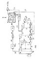
- a post combustion carbon dioxide (CO 2 ) capture system S air and fuel are fed into an industrial boiler A through lines 1 and 2 respectively.
- the fuel can be any typical hydrocarbon-based or fossil fuels that can combust in the presence of oxygen.
- the fuel is coal which when burned will also create an ash which can be removed from the boiler A through line 3.
- the boiler A will boil high pressure water fed through line 16 to produce high pressure steam. This steam is fed through line 26 to high pressure turbine B. A discharge steam from high pressure turbine B is typically fed back to the boiler A via line 4A.
- Reheated intermediate pressure steam is then fed to the intermediate pressure steam turbine C via line 4.
- Discharge steam from intermediate pressure turbine C, now at a low pressure is fed through line 6 to a low pressure turbine D.
- a discharge steam from low pressure turbine D is fed to a condenser E via line 8.
- Cooling water Q used in the condenser E is typically returned to a water cooling tower, before being recirculated back to the condenser E again.
- Condensed subatmospheric pressure steam is withdrawn from the condenser E as a cold water via line 9 and then fed to a water pump F. Pressurized cold water is then fed to a series of boiler feed water heaters G, H and J via corresponding lines 10, 13 and 15, respectively.
- Water pump I increases the pressure of water fed to a boiler A via line 16 to a level sufficiently high to produce the required high pressure steam fed through line 16 to the high pressure turbine B.
- a significant fraction of low pressure steam drawn from intermediate pressure turbine C via line 6 is directed toward the reboiler of the stripper in the post combustion capture plant P via line 17.
- this withdrawn steam is typically at pressures higher than 10 bar, while most of the solvents are thermally sensitive and unstable and consequently require steam for the reboiler typically below 6 BarA
- a back pressure steam turbine K to produce steam below approximately 6 BarA while producing significant amounts of electrical power which can typically cover all of the utility power needs of a post combustion capture plant P via line 22a and can also supply via line 22b a significant fraction of electrical power needed for carbon dioxide compression to supercritical conditions (typically at pressures as high as 150 BarA) when transported through CO 2 pipelines and used for Enhanced Oil Recovery (EOR) or underground sequestration.
- EOR Enhanced Oil Recovery
- Low pressure steam fed to the reboiler via line 23 is condensing to a hot water, while regenerating the solvent by partial vaporization, and is then being directed to boiler feed water heater H.
- the flue gas from the burning of the fuel from boiler A is fed through line 18 to an electrostatic precipitator M which will remove fine solids from the flue gas. Ash which is collected is removed through line 4C.
- the flue gas stream which is reduced in particle content is passed through line 19 to an induced draft (ID) fan N which directs the flue gas stream through line 20 into a flue gas desulfurization unit O where sulfur dioxide is removed.
- ID induced draft
- Absorbed carbon dioxide is transported with solvent to the stripper provided heat to the reboiler enhances the separation of carbon dioxide from solvent and is withdrawn from a condenser at the top of the stripper before further being compressed in a compressor L, further purified if necessary and then transported typically via CO 2 pipelines for final utilization, such as Enhanced Oil Recovery (EOR), for example.
- EOR Enhanced Oil Recovery
Landscapes
- Engineering & Computer Science (AREA)
- Chemical & Material Sciences (AREA)
- Combustion & Propulsion (AREA)
- Mechanical Engineering (AREA)
- General Engineering & Computer Science (AREA)
- Life Sciences & Earth Sciences (AREA)
- Sustainable Development (AREA)
- Sustainable Energy (AREA)
- Physics & Mathematics (AREA)
- Thermal Sciences (AREA)
- Treating Waste Gases (AREA)
- Gas Separation By Absorption (AREA)
Applications Claiming Priority (2)
| Application Number | Priority Date | Filing Date | Title |
|---|---|---|---|
| US201261605378P | 2012-03-01 | 2012-03-01 | |
| US13/778,437 US20140041394A1 (en) | 2012-03-01 | 2013-02-27 | Integration of power generation and post combustion capture plants |
Publications (1)
| Publication Number | Publication Date |
|---|---|
| EP2634482A2 true EP2634482A2 (de) | 2013-09-04 |
Family
ID=47900620
Family Applications (1)
| Application Number | Title | Priority Date | Filing Date |
|---|---|---|---|
| EP13157518.5A Withdrawn EP2634482A2 (de) | 2012-03-01 | 2013-03-01 | Verfahren zur Erzeugung von Elektrizität und Nachverbrennungserfassungssystem |
Country Status (2)
| Country | Link |
|---|---|
| US (1) | US20140041394A1 (de) |
| EP (1) | EP2634482A2 (de) |
Cited By (1)
| Publication number | Priority date | Publication date | Assignee | Title |
|---|---|---|---|---|
| CN109162810A (zh) * | 2018-08-23 | 2019-01-08 | 中国电力工程顾问集团西南电力设计院有限公司 | 一种用于分布式能源站的多能流测点系统 |
Families Citing this family (3)
| Publication number | Priority date | Publication date | Assignee | Title |
|---|---|---|---|---|
| GB201010760D0 (en) * | 2010-06-28 | 2010-08-11 | Doosan Power Systems Ltd | Operation of steam turbine and steam generator apparatus with post-combustion carbon capture |
| JP5738045B2 (ja) * | 2011-04-06 | 2015-06-17 | 三菱重工業株式会社 | 二酸化炭素の回収システム及び方法 |
| US20140250887A1 (en) * | 2013-03-05 | 2014-09-11 | Mitsubishi Heavy Industries, Ltd. | Power generation system making use of low grade coal |
Family Cites Families (9)
| Publication number | Priority date | Publication date | Assignee | Title |
|---|---|---|---|---|
| US9651253B2 (en) * | 2007-05-15 | 2017-05-16 | Doosan Power Systems Americas, Llc | Combustion apparatus |
| WO2009091437A1 (en) * | 2008-01-18 | 2009-07-23 | Powerspan Corp. | Removal of carbon dioxide from a flue gas stream |
| US8591627B2 (en) * | 2009-04-07 | 2013-11-26 | Innosepra Llc | Carbon dioxide recovery |
| EP2136037A3 (de) * | 2008-06-20 | 2011-01-05 | Siemens Aktiengesellschaft | Verfahren und Vorrichtung zum Betreiben einer Dampfkraftwerksanlage mit Dampfturbine und Prozessdampfverbraucher |
| US20100205964A1 (en) * | 2009-02-13 | 2010-08-19 | General Electric Company | Post-combustion processing in power plants |
| US8007570B2 (en) * | 2009-03-11 | 2011-08-30 | General Electric Company | Systems, methods, and apparatus for capturing CO2 using a solvent |
| US8171718B2 (en) * | 2009-10-05 | 2012-05-08 | General Electric Company | Methods and systems involving carbon sequestration and engines |
| CA2722195C (en) * | 2009-11-25 | 2013-03-19 | Hitachi, Ltd. | Fossil fuel combustion thermal power system including carbon dioxide separation and capture unit |
| GB0922142D0 (en) * | 2009-12-18 | 2010-02-03 | Doosan Babcock Energy Ltd | Regeneration of absorption solution |
-
2013
- 2013-02-27 US US13/778,437 patent/US20140041394A1/en not_active Abandoned
- 2013-03-01 EP EP13157518.5A patent/EP2634482A2/de not_active Withdrawn
Non-Patent Citations (1)
| Title |
|---|
| None |
Cited By (1)
| Publication number | Priority date | Publication date | Assignee | Title |
|---|---|---|---|---|
| CN109162810A (zh) * | 2018-08-23 | 2019-01-08 | 中国电力工程顾问集团西南电力设计院有限公司 | 一种用于分布式能源站的多能流测点系统 |
Also Published As
| Publication number | Publication date |
|---|---|
| US20140041394A1 (en) | 2014-02-13 |
Similar Documents
| Publication | Publication Date | Title |
|---|---|---|
| RU2454269C2 (ru) | Регенерация поглотителя обедненным раствором, подвергнутым мгновенному испарению, и интеграция тепла | |
| KR101401813B1 (ko) | 화석 연료 발전 설비의 배기 가스로부터 이산화탄소를 분리하기 위한 방법 및 장치 | |
| EP2089139B1 (de) | Verbesserte absorptionsmittelregeneration | |
| Cifre et al. | Integration of a chemical process model in a power plant modelling tool for the simulation of an amine based CO2 scrubber | |
| RU2358792C2 (ru) | Регенерация водного раствора, образующегося в процессе абсорбции кислых газов, путем многоступенчатого равновесного испарения и отгонки | |
| JP5964842B2 (ja) | Co2捕捉における熱統合 | |
| EP1827656B1 (de) | Verfahren zur entfernung und rückgewinnung von co2 aus einem abgas | |
| CN103096999A (zh) | 碳捕集喷气发动机 | |
| US9157369B2 (en) | Waste heat utilization for energy efficient carbon capture | |
| EP2105189A1 (de) | Verfahren und Vorrichtung zum Abtrennen von Kohlendioxid aus Rauchgas einer fossilbefeuerten Kraftwerksanlage | |
| US20120247104A1 (en) | System and method for controlling waste heat for co2 capture | |
| Baudoux et al. | Advanced configurations of amine based post-combustion carbon capture process applied to combined cycle gas turbine | |
| KR20110114189A (ko) | 탄소 포집 저장시스템 및 히트펌프 | |
| Harkin et al. | Process integration analysis of a brown coal-fired power station with CO2 capture and storage and lignite drying | |
| US20130199151A1 (en) | Steam Generator for Combined Cycle Gas Turbine Plant | |
| EP2634482A2 (de) | Verfahren zur Erzeugung von Elektrizität und Nachverbrennungserfassungssystem | |
| CN103534444A (zh) | 用于控制co2捕获用废热的系统和方法 | |
| RU2670998C2 (ru) | Энергетическая установка с кислородным бойлером с интегрированным по теплу блоком разделения воздуха | |
| US20140150699A1 (en) | Method and fossil-fuel-fired power plant for recovering a condensate | |
| CN104791031B (zh) | 一种与机组汽水系统整合的二氧化碳捕集再生系统 | |
| CN105509038A (zh) | 鼓泡流化床型o2/h2o增压富氧燃烧系统 | |
| CN113201370A (zh) | 一种电加热制取过热蒸汽的负压脱苯工艺及系统 | |
| KR101749287B1 (ko) | 공급수 저장 및 재순환 시스템 및 방법 | |
| CN118815559A (zh) | 集成大规模碳捕集燃煤电站及其变工况运行控制方法 | |
| EP2943267B1 (de) | Systeme und verfahren zur reduzierung des energiebedarfs einer kohlendioxiderfassungsanlage |
Legal Events
| Date | Code | Title | Description |
|---|---|---|---|
| PUAI | Public reference made under article 153(3) epc to a published international application that has entered the european phase |
Free format text: ORIGINAL CODE: 0009012 |
|
| AK | Designated contracting states |
Kind code of ref document: A2 Designated state(s): AL AT BE BG CH CY CZ DE DK EE ES FI FR GB GR HR HU IE IS IT LI LT LU LV MC MK MT NL NO PL PT RO RS SE SI SK SM TR |
|
| AX | Request for extension of the european patent |
Extension state: BA ME |
|
| STAA | Information on the status of an ep patent application or granted ep patent |
Free format text: STATUS: THE APPLICATION IS DEEMED TO BE WITHDRAWN |
|
| 18D | Application deemed to be withdrawn |
Effective date: 20171003 |