EP2634509B1 - Wärmequellenvorrichtung - Google Patents
Wärmequellenvorrichtung Download PDFInfo
- Publication number
- EP2634509B1 EP2634509B1 EP11836396.9A EP11836396A EP2634509B1 EP 2634509 B1 EP2634509 B1 EP 2634509B1 EP 11836396 A EP11836396 A EP 11836396A EP 2634509 B1 EP2634509 B1 EP 2634509B1
- Authority
- EP
- European Patent Office
- Prior art keywords
- flow rate
- heating
- heat exchanger
- control
- medium
- Prior art date
- Legal status (The legal status is an assumption and is not a legal conclusion. Google has not performed a legal analysis and makes no representation as to the accuracy of the status listed.)
- Active
Links
Images




Classifications
-
- F—MECHANICAL ENGINEERING; LIGHTING; HEATING; WEAPONS; BLASTING
- F25—REFRIGERATION OR COOLING; COMBINED HEATING AND REFRIGERATION SYSTEMS; HEAT PUMP SYSTEMS; MANUFACTURE OR STORAGE OF ICE; LIQUEFACTION SOLIDIFICATION OF GASES
- F25D—REFRIGERATORS; COLD ROOMS; ICE-BOXES; COOLING OR FREEZING APPARATUS NOT OTHERWISE PROVIDED FOR
- F25D29/00—Arrangement or mounting of control or safety devices
- F25D29/008—Alarm devices
-
- F—MECHANICAL ENGINEERING; LIGHTING; HEATING; WEAPONS; BLASTING
- F25—REFRIGERATION OR COOLING; COMBINED HEATING AND REFRIGERATION SYSTEMS; HEAT PUMP SYSTEMS; MANUFACTURE OR STORAGE OF ICE; LIQUEFACTION SOLIDIFICATION OF GASES
- F25B—REFRIGERATION MACHINES, PLANTS OR SYSTEMS; COMBINED HEATING AND REFRIGERATION SYSTEMS; HEAT PUMP SYSTEMS
- F25B1/00—Compression machines, plants or systems with non-reversible cycle
- F25B1/04—Compression machines, plants or systems with non-reversible cycle with compressor of rotary type
- F25B1/053—Compression machines, plants or systems with non-reversible cycle with compressor of rotary type of turbine type
-
- F—MECHANICAL ENGINEERING; LIGHTING; HEATING; WEAPONS; BLASTING
- F25—REFRIGERATION OR COOLING; COMBINED HEATING AND REFRIGERATION SYSTEMS; HEAT PUMP SYSTEMS; MANUFACTURE OR STORAGE OF ICE; LIQUEFACTION SOLIDIFICATION OF GASES
- F25B—REFRIGERATION MACHINES, PLANTS OR SYSTEMS; COMBINED HEATING AND REFRIGERATION SYSTEMS; HEAT PUMP SYSTEMS
- F25B25/00—Machines, plants or systems, using a combination of modes of operation covered by two or more of the groups F25B1/00 - F25B23/00
- F25B25/005—Machines, plants or systems, using a combination of modes of operation covered by two or more of the groups F25B1/00 - F25B23/00 using primary and secondary systems
-
- F—MECHANICAL ENGINEERING; LIGHTING; HEATING; WEAPONS; BLASTING
- F25—REFRIGERATION OR COOLING; COMBINED HEATING AND REFRIGERATION SYSTEMS; HEAT PUMP SYSTEMS; MANUFACTURE OR STORAGE OF ICE; LIQUEFACTION SOLIDIFICATION OF GASES
- F25B—REFRIGERATION MACHINES, PLANTS OR SYSTEMS; COMBINED HEATING AND REFRIGERATION SYSTEMS; HEAT PUMP SYSTEMS
- F25B49/00—Arrangement or mounting of control or safety devices
- F25B49/02—Arrangement or mounting of control or safety devices for compression type machines, plants or systems
-
- F—MECHANICAL ENGINEERING; LIGHTING; HEATING; WEAPONS; BLASTING
- F25—REFRIGERATION OR COOLING; COMBINED HEATING AND REFRIGERATION SYSTEMS; HEAT PUMP SYSTEMS; MANUFACTURE OR STORAGE OF ICE; LIQUEFACTION SOLIDIFICATION OF GASES
- F25B—REFRIGERATION MACHINES, PLANTS OR SYSTEMS; COMBINED HEATING AND REFRIGERATION SYSTEMS; HEAT PUMP SYSTEMS
- F25B5/00—Compression machines, plants or systems, with several evaporator circuits, e.g. for varying refrigerating capacity
- F25B5/02—Compression machines, plants or systems, with several evaporator circuits, e.g. for varying refrigerating capacity arranged in parallel
-
- F—MECHANICAL ENGINEERING; LIGHTING; HEATING; WEAPONS; BLASTING
- F25—REFRIGERATION OR COOLING; COMBINED HEATING AND REFRIGERATION SYSTEMS; HEAT PUMP SYSTEMS; MANUFACTURE OR STORAGE OF ICE; LIQUEFACTION SOLIDIFICATION OF GASES
- F25D—REFRIGERATORS; COLD ROOMS; ICE-BOXES; COOLING OR FREEZING APPARATUS NOT OTHERWISE PROVIDED FOR
- F25D17/00—Arrangements for circulating cooling fluids; Arrangements for circulating gas, e.g. air, within refrigerated spaces
- F25D17/02—Arrangements for circulating cooling fluids; Arrangements for circulating gas, e.g. air, within refrigerated spaces for circulating liquids, e.g. brine
-
- F—MECHANICAL ENGINEERING; LIGHTING; HEATING; WEAPONS; BLASTING
- F25—REFRIGERATION OR COOLING; COMBINED HEATING AND REFRIGERATION SYSTEMS; HEAT PUMP SYSTEMS; MANUFACTURE OR STORAGE OF ICE; LIQUEFACTION SOLIDIFICATION OF GASES
- F25B—REFRIGERATION MACHINES, PLANTS OR SYSTEMS; COMBINED HEATING AND REFRIGERATION SYSTEMS; HEAT PUMP SYSTEMS
- F25B2400/00—General features or devices for refrigeration machines, plants or systems, combined heating and refrigeration systems or heat-pump systems, i.e. not limited to a particular subgroup of F25B
- F25B2400/13—Economisers
-
- F—MECHANICAL ENGINEERING; LIGHTING; HEATING; WEAPONS; BLASTING
- F25—REFRIGERATION OR COOLING; COMBINED HEATING AND REFRIGERATION SYSTEMS; HEAT PUMP SYSTEMS; MANUFACTURE OR STORAGE OF ICE; LIQUEFACTION SOLIDIFICATION OF GASES
- F25B—REFRIGERATION MACHINES, PLANTS OR SYSTEMS; COMBINED HEATING AND REFRIGERATION SYSTEMS; HEAT PUMP SYSTEMS
- F25B2400/00—General features or devices for refrigeration machines, plants or systems, combined heating and refrigeration systems or heat-pump systems, i.e. not limited to a particular subgroup of F25B
- F25B2400/23—Separators
-
- F—MECHANICAL ENGINEERING; LIGHTING; HEATING; WEAPONS; BLASTING
- F25—REFRIGERATION OR COOLING; COMBINED HEATING AND REFRIGERATION SYSTEMS; HEAT PUMP SYSTEMS; MANUFACTURE OR STORAGE OF ICE; LIQUEFACTION SOLIDIFICATION OF GASES
- F25B—REFRIGERATION MACHINES, PLANTS OR SYSTEMS; COMBINED HEATING AND REFRIGERATION SYSTEMS; HEAT PUMP SYSTEMS
- F25B2700/00—Sensing or detecting of parameters; Sensors therefor
- F25B2700/19—Pressures
- F25B2700/197—Pressures of the evaporator
-
- F—MECHANICAL ENGINEERING; LIGHTING; HEATING; WEAPONS; BLASTING
- F25—REFRIGERATION OR COOLING; COMBINED HEATING AND REFRIGERATION SYSTEMS; HEAT PUMP SYSTEMS; MANUFACTURE OR STORAGE OF ICE; LIQUEFACTION SOLIDIFICATION OF GASES
- F25B—REFRIGERATION MACHINES, PLANTS OR SYSTEMS; COMBINED HEATING AND REFRIGERATION SYSTEMS; HEAT PUMP SYSTEMS
- F25B2700/00—Sensing or detecting of parameters; Sensors therefor
- F25B2700/21—Temperatures
- F25B2700/2116—Temperatures of a condenser
- F25B2700/21161—Temperatures of a condenser of the fluid heated by the condenser
-
- F—MECHANICAL ENGINEERING; LIGHTING; HEATING; WEAPONS; BLASTING
- F25—REFRIGERATION OR COOLING; COMBINED HEATING AND REFRIGERATION SYSTEMS; HEAT PUMP SYSTEMS; MANUFACTURE OR STORAGE OF ICE; LIQUEFACTION SOLIDIFICATION OF GASES
- F25B—REFRIGERATION MACHINES, PLANTS OR SYSTEMS; COMBINED HEATING AND REFRIGERATION SYSTEMS; HEAT PUMP SYSTEMS
- F25B2700/00—Sensing or detecting of parameters; Sensors therefor
- F25B2700/21—Temperatures
- F25B2700/2117—Temperatures of an evaporator
- F25B2700/21171—Temperatures of an evaporator of the fluid cooled by the evaporator
- F25B2700/21172—Temperatures of an evaporator of the fluid cooled by the evaporator at the inlet
-
- F—MECHANICAL ENGINEERING; LIGHTING; HEATING; WEAPONS; BLASTING
- F25—REFRIGERATION OR COOLING; COMBINED HEATING AND REFRIGERATION SYSTEMS; HEAT PUMP SYSTEMS; MANUFACTURE OR STORAGE OF ICE; LIQUEFACTION SOLIDIFICATION OF GASES
- F25B—REFRIGERATION MACHINES, PLANTS OR SYSTEMS; COMBINED HEATING AND REFRIGERATION SYSTEMS; HEAT PUMP SYSTEMS
- F25B2700/00—Sensing or detecting of parameters; Sensors therefor
- F25B2700/21—Temperatures
- F25B2700/2117—Temperatures of an evaporator
- F25B2700/21171—Temperatures of an evaporator of the fluid cooled by the evaporator
- F25B2700/21173—Temperatures of an evaporator of the fluid cooled by the evaporator at the outlet
Definitions
- the present invention relates to a heat source device of, for example, a centrifugal chiller or the like.
- a centrifugal chiller has been employed for realizing district cooling/heating, cooling/heating for a semiconductor factory or the like, and so forth.
- Fig. 8 shows a configuration diagram of a heat source system employing a conventional centrifugal chiller.
- a centrifugal chiller 70 cools chilled water (heating medium) supplied thereto from an external heat load 71, such as an air conditioner, a fan coil, or the like, to a predetermined temperature and supplies the cooled chilled water to the external load 71.
- a chilled-water pump 72 that feeds the chilled water is installed upstream of the centrifugal chiller 70 with respect to the flow of the chilled water.
- a chilled-water flow rate meter 73 that measures the flow rate of chilled water flowing out of the chilled-water pump 72 is provided downstream of the chilled-water pump 72.
- the output from this chilled-water flow rate meter 73 is sent to a control device (not shown) that controls the centrifugal chiller 70, and the centrifugal chiller 70 is controlled by using this chilled-water flow rate as one of the control parameters.
- JP 2005-233557 A discloses a refrigeration system.
- US 2,057,101 A discloses a refrigerating plant.
- a chilled-water flow rate meter and an electromagnetic flow rate meter are generally utilized as a chilled-water flow rate meter.
- an electromagnetic flow rate meter is expensive, and thus, adopting one sometimes is difficult.
- an electromagnetic flow rate meter is provided outside a centrifugal chiller, and, because data measured by the electromagnetic flow rate meter are taken into the centrifugal chiller as external data, there is a problem in that it is difficult to adjust the responsiveness etc.
- a centrifugal chiller is sometimes controlled by using a chilled-water flow rate estimated by using a pump characteristic curve obtained during test operation, instead of providing a chilled-water flow rate meter in a heat source system, various problems occur in the control because the estimated chilled-water flow rate is not very accurate, which forces an operator to go to the site each time to make adjustments or the like.
- the present invention has been conceived in light of the above-described circumstances, and an object thereof is to provide a heat source device that, by employing a low-cost sensor, is capable of obtaining sufficiently accurate information related to the state of a heating medium, such as the heating-medium flow rate or the like, and also enhancing control accuracy.
- the present invention employs the following solutions.
- the present invention provides a heat source device which is defined in claim 1.
- the differential pressure between the inlet pressure and the outlet pressure is measured for the heating medium at the first heat exchanger by using the differential pressure sensor, and the flow rate of the heating medium at the first heat exchanger is calculated by using the measurement data and the coefficient of loss that is specific to the first heat exchanger.
- the heat source device itself is provided with the configuration for calculating the heating-medium flow rate on the basis of the differential pressure of the heating medium in this way, it is possible to obtain a heating-medium flow rate that sufficiently satisfies the required accuracy with a low-cost, simple configuration.
- by correcting the control command on the basis of the current heating-medium flow rate obtained in this way it is possible to realize automatic fine control in accordance with a heating-medium flow rate at that time.
- the controlling means may determine a correction term that depends on the time lag in measuring the outlet pressure due to the amount of heating medium held in the first heat exchanger and may correct the flow rate of the heating medium by using the correction term.
- the flow rate is corrected by using the correction term that is dependent on the time lag in measuring the outlet pressure on the basis of the amount of heating medium held in the first heat exchanger, it is possible to eliminate an error on the basis of the amount of heating medium held in the first heat exchanger, and it is possible to enhance the accuracy of computing the heating-medium flow rate.
- the controlling means may include fault judging means for judging whether or not the difference between the heating-medium flow rate calculated by the flow-rate computing means and the specification heating-medium flow rate is equal to or greater than a predetermined threshold, which is set in advance, and for issuing an alarm, if the difference is equal to or greater than the threshold, to a monitoring device connected thereto via a communication line.
- the flow-rate computing means may include a first computing means for computing the heating-medium flow rate by using sampling data from the differential-pressure measuring means; and a second computing means for applying smoothing processing on the sampling data from the differential-pressure measuring means and for computing the heating-medium flow rate by using the smoothed sampling data, wherein the fault judging means may perform fault judgment by using the heating-medium flow rate calculated by the first computing means, and the control-command correcting means may correct the control command by using the heating-medium flow rate calculated by the second computing means.
- a fault is detected by the fault judging means on the basis of the heating-medium flow rate calculated on the basis of the sampling data from the differential-pressure measuring means, and the control command is corrected by the control-command correcting means on the basis of the heating-medium flow rate calculated from the data whose fluctuation range is reduced by applying smoothing processing to the sampling data from the differential-pressure measuring means. Accordingly, with a single differential pressure sensor, it is possible to detect a stoppage, where the flow rate suddenly changes, and it is also possible to realize stable control.
- a heat source device comprising: a first heat exchanger that cools or heats a heating medium that flows in from an external load; a second heat exchanger that performs heat exchange with external air or cooling water; a refrigerant circulating channel that circulates refrigerant between the first heat exchanger and the second heat exchanger; a centrifugal compressor provided in the refrigerant circulating channel; a differential-pressure measuring means for measuring a differential pressure between the inlet pressure and the outlet pressure of the heating medium in the first heat exchanger; a flow-rate measuring means for measuring a flow rate of the heating medium in the first heat exchanger; a temperature measuring means for measuring a temperature of the heating medium to be input to the first heat exchanger; and a controlling means, wherein the controlling means includes a heating-medium concentration computing means for calculating a specific weight of the heating medium based on the differential pressure output from the differential-pressure measuring means, the heating-medium flow rate output from the flow-rate measuring means, and
- the differential pressure between the inlet pressure and the outlet pressure is measured for the heating medium at the first heating exchanger by using the differential pressure sensor, and the concentration of the heating medium at the first heat exchanger is calculated by using the measurement data.
- the heat source device itself is provided with the configuration for calculating the heating-medium concentration on the basis of the heating-medium differential pressure in this way, it is possible to obtain a heating-medium concentration that sufficiently satisfies the required accuracy with a low-cost, simple configuration.
- by correcting the control command on the basis of the current heating-medium concentration obtained in this way it is possible to realize automatic fine control in accordance with a heating-medium concentration at that time.
- the controlling means may include a means for calculating an amount of heat exchanged at the first heat exchanger by substituting current power consumption at the centrifugal compressor and the amount of heat exchanged at the second heat exchanger into a relational expression that expresses the relationship between the power consumption at the centrifugal compressor, the amount of heat exchanged at the first heat exchanger, and the amount of heat exchanged at the second heat exchanger, and for calculating the heating-medium flow rate on the basis of the calculated amount of heat exchanged at the first heat exchanger.
- the heating-medium flow rate is obtained by using the relational expression described above, even in the case in which differential pressure cannot be detected because the differential-pressure measuring means has failed, a detection limit has been exceeded, and so forth, the heating-medium flow rate can be obtained, and control can be performed continuously.
- the controlling means may include a relational expression in which the relationship between the heating-medium flow rate and the performance of the heat exchanger is expressed and may include a means for determining the performance of the heat exchanger for the heating-medium flow rate calculated by the flow-rate computing means on the basis of the relational expression and for detecting a performance deterioration of the heat exchanger.
- an advantage is afforded in that, by employing a low-cost sensor, a sufficiently accurate heating-medium flow rate can be obtained, and control accuracy can also be enhanced.
- FIG. 1 shows, in outline, the configuration of a heat source system according to a first embodiment of the present invention.
- a heat source system 1 is provided with, for example, three centrifugal chillers (heat source devices) 11a, 11b, and 11c that are installed in a building or factory equipment and that take away heat from chilled water (heating medium) to be supplied to an external load 10, such as an air conditioner, a fan coil, or the like.
- centrifugal chillers 11a, 11b, and 11c are installed in parallel with the external load 10.
- Chilled water pumps 12a, 12b, and 12c that feed the chilled water are installed upstream, with respect to the flow of the chilled water, of the centrifugal chillers 11a, 11b, and 11c, respectively.
- the chilled water is sent to the individual centrifugal chillers 11a, 11b, and 11c from a return header 13 by means of the chilled water pumps 12a, 12b, and 12c.
- the individual chilled-water pumps 12a, 12b, and 12c are driven by inverter motors, and, by doing so, the rotational speed is made variable, enabling variable flow-rate control.
- the chilled water obtained at the individual centrifugal chillers 11a, 11b, and 11c is collected at a supply header 14.
- the chilled water collected at the supply header 14 is supplied to the external load 10.
- the chilled water whose temperature has been increased by being used for air conditioning or the like at the external load 10 is sent to the return header 13.
- the chilled water is branched at the return header 13 and is sent to the individual centrifugal chillers 11a, 11b, and 11c.
- FIG. 2 is a diagram showing, in outline, the configuration of the centrifugal chiller 11a.
- the centrifugal chiller 11a is provided with a centrifugal compressor 20 that compresses refrigerant; a condenser (second heat exchanger) 21 that condenses high-temperature, high-pressure gaseous refrigerant compressed by the centrifugal compressor 20; a subcooler 22 that supercools liquid refrigerant condensed at the condenser 21; a high-pressure expansion valve 23 that causes the liquid refrigerant from the subcooler 22 to expand; an intermediate cooling unit 25 that is connected to the high-pressure expansion valve 23, an intermediate stage of the centrifugal compressor 20, and a low-pressure expansion valve 24; and an evaporator (first heat exchanger) 26 that evaporates the liquid refrigerant expanded at the low-pressure expansion valve 24.
- a centrifugal compressor 20 that compresses refrigerant
- a condenser (second heat exchanger) 21 that condenses high-temperature, high-pressure gaseous refrigerant compressed by the centrifugal compressor 20
- the centrifugal compressor 20 is a centrifugal two-stage compressor and is driven by an electrical motor 28 whose rotational speed is controlled by an inverter 27.
- the output power of the inverter 27 is controlled by a control device 30.
- the centrifugal compressor 20 may be a fixed-speed compressor having a constant rotational speed.
- an inlet guide vane (hereinafter, referred to as "IGV") 29 that controls the flow rate of the refrigerant to be sucked thereinto is provided, which makes it possible to perform capacity control for the centrifugal chiller 11a.
- the condenser 21 is provided with a pressure sensor 35 for measuring the condenser pressure (condensed refrigerant pressure). An output Pc from the pressure sensor 35 is sent to the control device 30.
- the subcooler 22 Downstream of the condenser 21 with respect to the refrigerant flow, the subcooler 22 is provided so as to supercool the condensed refrigerant. Immediately downstream of the subcooler 22 with respect to the refrigerant flow, a temperature sensor 36 that measures a supercooled refrigerant temperature Ts is provided.
- a cooling heat-conducting tube 33 for cooling the condenser 21 and the subcooler 22 is inserted thereinto so as to pass through them.
- a cooling-liquid flow rate is determined by means of computation on the basis of an inlet-outlet differential pressure of the chilled water measured by a differential pressure sensor 37; a cooling-water outlet temperature Tcout is measured by a temperature sensor 38; and a cooing-water inlet temperature Tcin is measured by a temperature sensor 39.
- the cooling water externally exhausts heat at a cooling tower (not shown), after which it is guided to the condenser 21 and the subcooler 22 again.
- the intermediate cooling unit 25 is provided with a pressure sensor 40 for measuring an intermediate pressure Pm.
- a differential pressure sensor 41 for measuring an inlet-outlet differential pressure dPe of the chilled water is provided at chilled-water inlet/outlet of the evaporator 26. Chilled water of a rated temperature (for example, 7 °C) is obtained by means of heat absorption at the evaporator 26.
- a chilled-water heat conducting tube 34 for cooling the chilled water to be supplied to the external load 10 (see Fig. 1 ) is inserted into the evaporator 26 so as to pass therethrough.
- a chilled-water outlet temperature Tout is measured by a temperature sensor 42; a chilled-water inlet temperature Tin is measured by a temperature sensor 43; and an evaporator pressure Pe is measured by a pressure sensor 26.
- a hot-gas bypass pipe 32 is provided between a gas phase in the condenser 21 and a gas phase in the evaporator 26. Then a hot-gas bypass valve 31 for controlling the flow rate of the refrigerant that flows inside the hot-gas bypass pipe 32 is provided. By adjusting the hot-gas bypass flow rate by means of the hot-gas bypass valve 31, capacity control becomes possible in an extremely low load region where the control by the IGV 29 is not sufficient.
- centrifugal chiller 11a employed in this embodiment is not limited to a centrifugal chiller having only the cooling function described above, and, for example, it may have only the heating function or both the cooling function and the heating function.
- the control device 30 is formed of, for example, a CPU (central processing unit), a ROM (Read Only Memory), a RAM (Random Access Memory), and so on. Steps of a processing sequence for realizing various functions, described later, are recorded in the ROM or the like in the form of a program, and the CPU loads this program into the RAM or the like and executes information processing and computational processing, thereby realizing various functions to be described later.
- a CPU central processing unit
- ROM Read Only Memory
- RAM Random Access Memory
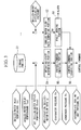
- Fig. 3 is a functional block diagram showing, in an expanded manner, the functions the control device 30 is provided with.
- the control device 30 is provided with, as main components, a storage portion 51, a chilled-water flow-rate computing portion 52, a fault judging portion 53, an operating-state determining portion 54, a control-command computing portion 55, and a control-command correcting portion 56.
- the chilled-water flow-rate computing portion 52 possesses Equation (1) below, and calculates a chilled-water flow rate qa by substituting the measured value dPe from the differential pressure sensor 41 into this Equation.
- ⁇ is a coefficient of loss for the evaporator 26, which is stored in the storage portion 51.
- qa ⁇ dPe
- the chilled-water flow-rate computing portion 52 may apply smoothing processing to the sampling data measured by the differential pressure sensor 41, by using a technique such as a moving average, and may calculate the chilled-water flow rate qa from Equation (1) above by using the processed data.
- the chilled-water flow-rate computing portion 52 may calculate the chilled-water flow rate qa by using a computational equation in which a correction term with regard to the temperature dependency of the chilled-water flow rate qa in the evaporator 26 is additionally reflected in Equation (1) above.
- the chilled-water flow rate qa may be calculated by using a computational equation in which a correction term on the basis of the amount of liquid held in the evaporator 26 is added to Equation (1) above in order to eliminate an error in the differential pressure due to this time lag.
- the fault judging portion 53 calculates a difference between the chilled-water flow rate qa computed by the chilled-water flow-rate computing portion 42 and a specification chilled-water flow rate qs, which is set in advance, and when this difference is equal to or greater than a predetermined threshold, which is set in advance, the fault judging portion 53 notifies, by means of an alarm, a monitoring device of the heat source system to which it is connected via a communication line.
- the operating-state determining portion 54 determines the current operating state by using various information related to the centrifugal chiller saved in the storage portion 51, as well as input data measured by the individual sensors, such as, for example, the chilled-water inlet temperature Tin, the chilled-water outlet temperature Tout, a set chilled-water outlet temperature Toset, the specification chilled-water flow rate qs, the evaporator pressure Pe, the condenser pressure Pc, the intermediate cooling-unit pressure Pm, and so forth.
- the control-command computing portion 55 generates individual control commands on the basis of the operating state determined by the operating-state determining portion 54. Note that, because the processing performed by the operating-state determining portion 54 and the control-command computing portion 55 is known processing, details thereof are omitted.
- the control-command correcting portion 56 calculates a correction value for correcting the control commands for the centrifugal chiller on the basis of the difference between the chilled-water flow rate qa and the specification chilled-water flow rate qs and corrects the control commands determined by the control-command computing portion 55 by using this correction value.
- the control-command correcting portion 56 possesses a computational equation for obtaining a correction value in which the difference between the chilled-water flow rate qa and the specification chilled-water flow rate qs serves as a variable and obtains a correction value by substituting the difference calculated at the fault judging portion 53 into this computational equation. With this correction value, a command value to be provided for controlling the rotational speed of an electric motor is corrected.
- the chilled-water flow rate computing portion 52 calculates the chilled-water flow rate qa from Equation (1) above by using the data dPe measured by the differential pressure sensor 41; and the fault judging portion 53 determines the difference between the calculated chilled-water flow rate qa and the specification chilled-water flow rate qs, which is set in advance, judges whether or not this difference is equal to or greater than the predetermined threshold, which is set in advance, and notifies, by means of an alarm, the monitoring device of the heat source system if the difference is equal to or greater than the threshold.
- the operating-state determining portion 54 determines the current operating state by using the predetermined information saved in the storage portion 51, as well as sensor values such as the chilled-water inlet temperature Tin and so forth; and the control-command computing portion 55 generates the individual control commands on the basis of the current operating state and provides the control-command correcting portion 56 with the generated control commands.
- the control-command correcting portion 56 calculates the correction values for correcting the control commands for the centrifugal chiller on the basis of the difference between the chilled-water flow rate qa and the specification chilled-water flow rate qs, and the control commands determined by the control-command computing portion 55 are corrected by using the correction values.
- the control commands corrected by the control-command correcting portion 56 are provided to the individual components to be controlled, and, by doing so, control is performed on the basis of the chilled-water flow rate qa calculated on the basis of the chilled-water differential pressure dPe.
- the centrifugal chiller itself is provided with the configuration for calculating the chilled-water flow rate on the basis of the chilled-water differential pressure, it is possible to obtain a chilled-water flow rate that sufficiently satisfies the required accuracy with a low-cost, simple configuration.
- by correcting control commands on the basis of a current chilled-water flow rate obtained in this way it is possible to realize automatic fine control in accordance with the chilled-water flow rate at that time.
- a protection function sensor 74 is provided in addition to an electromagnetic flow rate meter 73 or the like for measuring a flow rate to be used in controlling a centrifugal chiller 70, so that, when stoppage, freezing, and so forth of the chilled water occurs, the fault can quickly be detected, and thus, the state of the chilled water is monitored by the two sets of sensors.
- the electromagnetic flow rate meter 73 fluctuate due to disturbances such as opening and closing of valves or the like, the control of the centrifugal chiller 70 becomes unstable if the data are used without modification.
- the sampling data measured by the electromagnetic flow rate meter 73 is subjected to smoothing processing at an adjusting circuit (not shown) to reduce the fluctuations, and the chilled-water flow rate data whose fluctuations have been reduced are sent to a control device (not shown) in the centrifugal chiller 70.
- a fault detecting sensor is separately provided in order to eliminate this problem, and a fault such as a stoppage or the like is detected on the basis of data from this fault detecting sensor.
- the centrifugal chiller 11a itself has the differential pressure sensor 41 as described above, by storing the property data or the like for this differential pressure sensor 41 in the control device 30, the sampling data from the differential pressure sensor 41 can be adjusted at the control device 30 in accordance with the usage thereof.
- the centrifugal chiller 11a itself has the differential pressure sensor 41 as described above, by storing the property data or the like for this differential pressure sensor 41 in the control device 30, the sampling data from the differential pressure sensor 41 can be adjusted at the control device 30 in accordance with the usage thereof.
- the chilled-water flow-rate computing portion 52 may be provided with a first computing portion 521 that computes the chilled-water flow rate by using the sampling data from the differential pressure sensor 41 without modification and a second computing portion 522 that applies known smoothing processing, such as a moving average, to the sampling data from the differential pressure sensor 41 and that calculates the chilled-water flow rate on the basis of the processed data; the fault judging portion 53 may detect a fault on the basis of the chilled-water flow rate calculated by the first computing portion 521; and the control-command correcting portion 56 may correct the control commands on the basis of the chilled-water flow rate calculated by the second computing portion 522.
- the two purposes that is, control of the centrifugal chiller and detection of a fault, can be achieved by a single differential pressure sensor 41, and it is possible to eliminate installation of two sets of sensors such as those shown in Fig. 8 .
- the control device 30 may be additionally provided with a function for notifying, by means of an alarm, the monitoring device of the heat source system or a function for performing an appropriate protective control operation, by which the performance of the evaporator is judged to be deteriorating when the chilled-water flow rate is equal to or less than a predetermined threshold, which is set in advance, or when the chilled-water flow rate is detected to be continuously decreasing over a predetermined period.
- centrifugal chiller 11a by additionally providing the control device 30 with a function for detecting performance deterioration of the evaporator 26 on the basis of the chilled-water flow rate qa in this way, it is possible to quickly take appropriate measures.
- the chilled water has been described as an example of a heating medium, it is not limited to this example, and, for example, brine (for example, antifreeze such as ethylene glycol, etc.) or the like may be employed.
- brine for example, antifreeze such as ethylene glycol, etc.
- centrifugal chiller according to an additional example, which is not claimed but is included for illustrative purposes, will be described.
- the centrifugal chiller according to this example is employed in a heat source system in which brine (for example, antifreeze such as ethylene glycol, etc.) is utilized as a heating medium instead of chilled water; the brine concentration is calculated instead of the chilled-water flow rate; and the control commands for the centrifugal chiller are corrected by using the calculated brine concentration.
- brine for example, antifreeze such as ethylene glycol, etc.
- Fig. 6 is a functional block diagram of a control device according to this example.
- the control device according to this example is provided with, as main components, a storage portion 61, a brine-concentration computing portion 62, a fault judging portion 63, an operating-state determining portion 65, a control-command computing portion 66, and a control-command correcting portion 67.
- a brine differential pressure is measured by the differential pressure meter 41 in the evaporator 26 in Fig. 2 .
- information related to the centrifugal chiller that is necessary for the individual portions described above to perform computations, data about the physical properties of the brine, and so forth are saved in the storage portion 61.
- the brine-concentration computing portion 62 calculates the brine concentration on the basis of the brine differential pressure. Equation (2) and Equation (3) below are used to calculate the brine concentration.
- the brine concentration X is determined from the specific weight p of the brine, the average temperature T between an inlet temperature Tin and an outlet temperature Tout of the brine, and physical properties of the brine saved in the storage portion 61.
- the specific weight p of the brine is calculated on the basis of a brine flow rate q measured by a separately provided flow rate meter (not shown) or the like, a brine differential pressure measured by the differential pressure meter 41, and pressure-loss characteristics or the like saved in the storage portion 61.
- the fault judging portion 63 calculates the difference between the brine concentration computed by the brine-concentration computing portion 62 and a specification brine concentration, which is set in advance, and, if this difference is equal to or greater than a predetermined threshold that is set in advance, the fault judging portion 63 notifies, by means of an alarm, a monitoring device of the heat source system to which it is connected via a communication line.
- the operating-state determining portion 65 determines the current operating state by using various kinds of information about the centrifugal chiller saved in the storage portion 61, as well as input data measured by the individual sensors, such as, for example, the brine inlet temperature Tin, the brine outlet temperature Tout, a set brine outlet temperature Toset, the brine flow rate q, the evaporator pressure Pe, condenser pressure Pc, the intermediate cooling-unit pressure Pm, and so forth.
- the control-command computing portion 66 generates individual control commands on the basis of the operating state determined by the operating-state determining portion 56. Note that, because processing performed by the operating-state determining portion 65 and the control-command computing portion 66 involves generation of control commands on the basis of the individual sensor values, which is known processing, details thereof are omitted.
- the control-command correcting portion 67 calculates a correction value for correcting the control commands for the centrifugal chiller on the basis of the current brine concentration determined by the brine-concentration computing portion 62 and corrects the control commands determined by the control-command computing portion 66 by using this correction value.
- the control-command correcting portion 67 possesses a computational equation for obtaining a correction value in which the brine concentration serves as a variable and obtains a correction value by substituting the brine concentration calculated at the brine-concentration computing portion 62 into this computational equation.
- a command value to be provided for controlling the rotational speed of an electric motor is corrected by the control-command correcting portion 67.
- the brine-concentration computing portion 62 calculates the brine concentration; and the fault judging portion 63 judges whether or not the difference between the calculated brine concentration and the specification brine concentration, which is set in advance, is equal to or greater than the predetermined threshold, which is set in advance, and notifies the monitoring device of the heat source system about a fault via the communication line if the threshold is reached or exceeded. Accordingly, at a monitoring facility on the heat source system side, it is possible to recognize the risk of freezing or the like due to a decrease in the brine concentration. In addition, when a fault is not detected, the current brine concentration calculated by the brine-concentration computing portion 62 is output to the control-command correcting portion 67.
- the operating-state determining portion 65 determines the current operating state by using the predetermined information saved in the storage portion 61, as well as sensor values such as the brine inlet temperature Tin and so forth; and the control-command computing portion 66 generates the individual control commands on the basis of the current operating state and provides the control-command correcting portion 67 with the generated control commands.
- the control-command correcting portion 67 calculates the correction value for correcting the control commands for the centrifugal chiller by using the current brine concentration, and the control commands determined by the control-command computing portion 66 are corrected by using this correction value.
- the control command values corrected by the control-command correcting portion 67 are provided to the individual components to be controlled, and, by doing so, control is performed on the basis of the brine concentration calculated on the basis of the brine differential pressure.
- the centrifugal chiller itself is provided with the configuration for calculating the brine concentration on the basis of the brine differential pressure, it is possible to obtain a brine concentration that sufficiently satisfies the required accuracy with a low-cost, simple configuration.
- the alarm is issued when the difference between the actual brine concentration and the specification concentration thereof exceeds the predetermined threshold, it is possible to notify, by means of this alarm, operators on the heat source system side about the risk of freezing or the like due to a decrease in the brine concentration.
- a fault may be detected on the basis of whether or not the brine flow rate is within a predetermined range, instead of the brine concentration.
- control commands on the basis of the actual brine concentration can be employed when the brine concentration is within a normal range, and it is possible to realize automatic fine control in accordance with the brine conditions.
- centrifugal chiller may also be provided with the functions of the first computing portion 521 and the second computing portion 522 shown in Fig. 4 , or the function for detecting a performance deterioration of the evaporator 26 shown in Fig. 5 .
- the heating-medium differential pressure of chilled water or brine is measured, and the heating-medium flow rate is determined on the basis of this differential pressure; however, for example, if the differential pressure meter 41 that measures the heating-medium differential pressure fails, there will be a problem in calculating the flow rate.
- a heating-medium flow rate is calculated by means of computation on the basis of a heat-balance relational expression for the centrifugal chiller.
- Equation (4) Qe is the amount of heat exchanged at the evaporator, Qm is the power consumed by the centrifugal compressor, and Qc is the amount of heat exchanged at the condenser.
- Qe and Qc can be determined by the following Equation (5) and Equation (6), respectively.
- Qe Cpe ⁇ ⁇ e ⁇ qe ⁇ Tout ⁇ Tin
- Cpe is the specific heat [kJ/(kg ⁇ K)] of the heating medium; pe is the density [kg/m 3 ] of the heating medium; qe is the volumetric flow rate [m 3 /s] of the heating medium; Tout is the outlet temperature [K] of the heating medium measured by the temperature sensor 42 in Fig. 2 ; and Tin is the inlet temperature [K] of the heating medium measured by the temperature sensor 43 in Fig. 2 .
- Qc Cpc ⁇ ⁇ c ⁇ qc ⁇ Tcout ⁇ Tcin
- Cpc is the specific heat [kJ/(kg ⁇ K)] of the cooling water; pc is the density [kg/m 3 ] of the cooling water; qc is the volumetric flow rate [m 3 /s] of the cooling water computed on the basis of outlet-inlet differential pressure of the cooling water measured by the differential pressure sensor 37 in Fig. 2 ; Tcout is the outlet temperature [K] of the cooling water measured by the temperature sensor 38 in Fig. 2 ; and Tcin is the inlet temperature [K] of the cooling water measured by the temperature sensor 39 in Fig. 2 .
- the power consumption Qm is constantly measured by the control device.
- the flow rate of the heating medium can be obtained by calculating the flow rate of the heating medium by means of computation from the relational expression expressed by Equation (4) above. Accordingly, for example, even in the case in which differential pressure cannot be detected because the differential pressure sensor 41 has failed, the detection limit has been exceeded, and so forth, the heating-medium flow rate can be obtained, and control can be performed continuously.
- the flow rate of the cooling water can be calculated even when the sensor on the cooling water side fails.
- the cooling water is in an open system that passes through a cooling tower or the like, as compared with a heating-medium heat conducting tube forming a closed system, dirt easily accumulates in the cooling heat conducting tube 33 in which the cooling water circulates, which tends to lower the accuracy of measuring the flow rate of the cooling water; however, in this case, the flow rate of the cooling water can be obtained with sufficient accuracy by using the relational expression above.
- the heating-medium flow rate is compared with the specification heating-medium flow rate, which is set in advance, in order to identify for which of the heating-medium flow rate and the cooling-water flow rate a fault is occurring, and, if the error thereof is within a predetermined range, it can be judged that a failure or the like has occurred in the flow rate sensor for the cooling water.
- the flow rate of the chilled water or the cooling water which has a smaller fluctuation range, may be obtained by using the heat-balance relational expression above. Accordingly, stable flow rate values can be obtained as indicated by a dotted line in Fig. 7 .
Landscapes
- Engineering & Computer Science (AREA)
- Physics & Mathematics (AREA)
- Mechanical Engineering (AREA)
- Thermal Sciences (AREA)
- General Engineering & Computer Science (AREA)
- Chemical & Material Sciences (AREA)
- Combustion & Propulsion (AREA)
- Air Conditioning Control Device (AREA)
Claims (5)
- Wärmequellenvorrichtung (1), die Folgendes umfasst:einen ersten Wärmetauscher (26), der ein Heizmedium, das von einer externen Last (10) einströmt, kühlt oder erwärmt;einen zweiten Wärmetauscher (21), der mit Außenluft oder Kühlwasser einen Wärmeaustausch durchführt;einen Kältemittelzirkulationskanal, der Kältemittel zwischen dem ersten Wärmetauscher (26) und dem zweiten Wärmetauscher (21) zirkuliert;einen Zentrifugalverdichter (20), der im Kältemittelzirkulationskanal bereitgestellt ist und von einem Elektromotor (28), dessen Drehgeschwindigkeit von einem Wandler (27) gesteuert wird, angetrieben wird;wobeidie Wärmequellenvorrichtung (1) ferner ein Differenzdruckmessmittel (41) zum Messen eines Differenzdrucks zwischen einem Einlassdruck und einem Auslassdruck des Heizmediums im ersten Wärmetauscher (26) umfasst; undein Steuermittel (30), das dazu ausgelegt ist, die Wärmequellenvorrichtung (1) zu steuern,wobei das Steuermittel (30) Folgendes beinhalteteinen Speicherabschnitt (51), ein Durchflussratenberechnungsmittel (52) zum Errechnen einer Durchflussrate (qa) des Heizmediums im ersten Wärmetauscher (26) auf Basis des Verlustkoeffizienten (ζ) für den ersten Wärmetauscher (26), der im Speicherabschnitt (51) gespeichert ist, und des Differenzdrucks (dPe), der vom Differenzdruckmessmittel (41) ausgegeben wird;ein Steuerbefehlberechnungsmittel (55, 66) zum Erzeugen eines Steuerbefehls, der jedem von Steuerungszielen der Wärmequellenvorrichtung (1) bereitgestellt wird, unter Verwendung einer Spezifikationsheizmediumdurchflussrate, die vorab eingestellt wird; undein Steuerbefehlkorrekturmittel (56, 67) zum Korrigieren von jedem der Steuerbefehle, die vom Steuerbefehlberechnungsmittel (55, 66) erzeugt werden, auf Basis der Differenz zwischen der Heizmediumdurchflussrate, die vom Durchflussratenberechnungsmittel (52) errechnet wird, und der Spezifikationsheizmediumdurchflussrate,wobei das Steuermittel (30) einen Steuerbefehl verwendet, der vom Steuerbefehlkorrekturmittel (56, 67) korrigiert wird, um die Drehgeschwindigkeit des Elektromotors (28) mittels des Wandlers (27) zu steuern, undwobei das Durchflussratenberechnungsmittel (52) die folgende Gleichung besitzt und die Durchflussrate (qa) des Heizmediums im ersten Wärmetauscher (26) durch Einsetzen des Differenzdrucks (dPe), der vom Differenzdruckmessmittel (41) ausgegeben wird, in die Gleichung errechnet

- Wärmequellenvorrichtung (1) nach Anspruch 1, wobei das Steuermittel (30) ein Fehlerbeurteilungsmittel (53, 63) zum Beurteilen, ob die Differenz zwischen der Heizmediumdurchflussrate, die vom Durchflussratenberechnungsmittel (52) errechnet wird, und der Spezifikationsheizmediumdurchflussrate gleich oder größer als ein vorbestimmter Schwellwert, der vorab eingestellt wird, ist oder nicht, und zum Ausgeben eines Alarms, wenn die Differenz gleich oder größer als der Schwellwert ist, an eine Überwachungsvorrichtung, die via eine Kommunikationsleitung damit verbunden ist, beinhaltet.
- Wärmequellenvorrichtung (1) nach Anspruch 2, wobei das Durchflussratenberechnungsmittel (52) Folgendes beinhaltet
ein erstes Berechnungsmittel (521) zum Berechnen der Heizmediumdurchflussrate unter Verwendung von Stichprobendaten vom Differenzdruckmessmittel (41); und
ein zweites Berechnungsmittel (522) zum Anwenden einer Glättungsverarbeitung an den Stichprobendaten vom Differenzdruckmessmittel (41) und zum Berechnen der Heizmediumdurchflussrate unter Verwendung der geglätteten Stichprobendaten,
wobei das Fehlerbeurteilungsmittel (53, 63) unter Verwendung der Heizmediumdurchflussrate, die vom ersten Berechnungsmittel (521) errechnet wird, eine Fehlerbeurteilung durchführt und das Steuerbefehlkorrekturmittel (56, 67) unter Verwendung der Heizmediumdurchflussrate, die vom zweiten Berechnungsmittel (522) errechnet wird, den Steuerbefehl korrigiert. - Wärmequellenvorrichtung (1) nach einem der Ansprüche 1 bis 3, wobei das Steuermittel (30) ein Mittel zum Errechnen einer Wärmemenge, die am ersten Wärmetauscher (26) ausgetauscht wird, durch Einsetzen eines aktuellen Stromverbrauchs am Zentrifugalverdichter (20) und der Wärmemenge, die am zweiten Wärmetauscher (21) ausgetauscht wird, in einen relationalen Ausdruck, der die Beziehung zwischen dem Stromverbrauch am Zentrifugalverdichter (20), der Wärmemenge, die am ersten Wärmetauscher (26) ausgetauscht wird, und der Wärmemenge, die am zweiten Wärmetauscher (21) ausgetauscht wird, ausdrückt, und zum Errechnen der Heizmediumdurchflussrate auf Basis der errechneten Wärmemenge, die am ersten Wärmetauscher (26) ausgetauscht wird, beinhaltet.
- Wärmequellenvorrichtung (1) nach einem der Ansprüche 1 bis 4, wobei
das Steuermittel (30) einen relationalen Ausdruck beinhaltet, in dem die Beziehung zwischen der Heizmediumdurchflussrate und der Leistung des ersten Wärmetauschers (26) ausgedrückt wird, und ein Mittel zum Bestimmen der Leistung des ersten Wärmetauschers (26) für die Heizmediumdurchflussrate, die vom Durchflussratenberechnungsmittel (52) auf Basis des relationalen Ausdrucks errechnet wird, und zum Detektieren einer Leistungsminderung des ersten Wärmetauschers (26) beinhaltet.
Applications Claiming Priority (2)
| Application Number | Priority Date | Filing Date | Title |
|---|---|---|---|
| JP2010244067A JP5761960B2 (ja) | 2010-10-29 | 2010-10-29 | 熱源装置 |
| PCT/JP2011/074815 WO2012057263A1 (ja) | 2010-10-29 | 2011-10-27 | 熱源装置 |
Publications (3)
| Publication Number | Publication Date |
|---|---|
| EP2634509A1 EP2634509A1 (de) | 2013-09-04 |
| EP2634509A4 EP2634509A4 (de) | 2016-10-12 |
| EP2634509B1 true EP2634509B1 (de) | 2020-08-26 |
Family
ID=45993966
Family Applications (1)
| Application Number | Title | Priority Date | Filing Date |
|---|---|---|---|
| EP11836396.9A Active EP2634509B1 (de) | 2010-10-29 | 2011-10-27 | Wärmequellenvorrichtung |
Country Status (5)
| Country | Link |
|---|---|
| US (1) | US9605893B2 (de) |
| EP (1) | EP2634509B1 (de) |
| JP (1) | JP5761960B2 (de) |
| CN (1) | CN103348195B (de) |
| WO (1) | WO2012057263A1 (de) |
Families Citing this family (17)
| Publication number | Priority date | Publication date | Assignee | Title |
|---|---|---|---|---|
| JP2014159923A (ja) * | 2013-02-20 | 2014-09-04 | Ebara Refrigeration Equipment & Systems Co Ltd | ターボ冷凍機 |
| JP6296279B2 (ja) * | 2013-12-13 | 2018-03-20 | オリオン機械株式会社 | 温度調整装置 |
| JP2015114075A (ja) * | 2013-12-13 | 2015-06-22 | オリオン機械株式会社 | 温度調整装置 |
| GB2552084B (en) | 2014-01-29 | 2018-08-01 | Illinois Tool Works | A locker system |
| JP6498411B2 (ja) * | 2014-10-10 | 2019-04-10 | 三菱重工サーマルシステムズ株式会社 | 熱源システム及びその冷却水制御装置並びに制御方法 |
| CN104280074B (zh) * | 2014-10-27 | 2016-08-24 | 宋建峰 | 远程可编程式智能厨房安全探测终端 |
| JP6422398B2 (ja) * | 2015-05-25 | 2018-11-14 | 荏原冷熱システム株式会社 | 冷凍機 |
| KR101659979B1 (ko) * | 2015-08-25 | 2016-09-26 | (주)대성마리프 | 저온 저장고의 온도 및 습도의 임의 제어가 가능한 간접 냉각 시스템 |
| JP6682301B2 (ja) * | 2016-03-08 | 2020-04-15 | 三菱重工サーマルシステムズ株式会社 | 蒸気圧縮式冷凍機及びその制御方法 |
| JP6897079B2 (ja) * | 2016-12-08 | 2021-06-30 | 株式会社Ihi | 熱処理装置 |
| JP6707192B2 (ja) * | 2017-05-19 | 2020-06-10 | 三菱電機株式会社 | チリングユニット及び水循環温調システム |
| CN112325558A (zh) * | 2019-08-05 | 2021-02-05 | 长鑫存储技术有限公司 | 载物台水冷装置及其故障检测方法 |
| JP2022018707A (ja) * | 2020-07-16 | 2022-01-27 | 三菱重工サーマルシステムズ株式会社 | 異常検知システム及び冷凍機、並びに異常検知方法、並びに異常検知プログラム |
| US12181193B2 (en) | 2020-08-19 | 2024-12-31 | Honeywell International Inc. | Vapor cycle cooling system for high powered devices |
| EP4368915A4 (de) * | 2021-07-08 | 2024-08-21 | Mitsubishi Electric Corporation | Wärmepumpensystem |
| WO2023043363A1 (en) * | 2021-09-20 | 2023-03-23 | Qvantum Industries Ab | A heat pump for heating or cooling, a method, and a computer program product therefor |
| JP2023119243A (ja) * | 2022-02-16 | 2023-08-28 | 三浦工業株式会社 | 処理装置 |
Family Cites Families (26)
| Publication number | Priority date | Publication date | Assignee | Title |
|---|---|---|---|---|
| US2057101A (en) | 1933-04-29 | 1936-10-13 | Sulzer Ag | Refrigerating plant |
| US4972903A (en) * | 1990-01-25 | 1990-11-27 | Phillips Petroleum Company | Heat exchanger |
| US5083438A (en) * | 1991-03-01 | 1992-01-28 | Mcmullin Larry D | Chiller monitoring system |
| KR100296671B1 (ko) * | 1992-08-10 | 2001-10-24 | 스티븐에스. 그레이스 | 압축기의제어와모니터링을위한장치및공정 |
| JP3121735B2 (ja) * | 1994-12-16 | 2001-01-09 | 株式会社クボタ | 双方向流量計測方法およびその装置 |
| US6442964B1 (en) * | 1998-10-15 | 2002-09-03 | Ebara Corporation | Absorption refrigerating machine |
| WO2000040185A1 (en) * | 1999-01-04 | 2000-07-13 | Medivance, Incorporated | Improved cooling/heating pad and system |
| US6601397B2 (en) * | 2001-03-16 | 2003-08-05 | Copeland Corporation | Digital scroll condensing unit controller |
| US6718779B1 (en) * | 2001-12-11 | 2004-04-13 | William R. Henry | Method to optimize chiller plant operation |
| JP4102564B2 (ja) | 2001-12-28 | 2008-06-18 | 忠弘 大見 | 改良型圧力式流量制御装置 |
| JP2005090816A (ja) | 2003-09-16 | 2005-04-07 | Matsushita Electric Ind Co Ltd | ヒートポンプ給湯装置 |
| US7357000B2 (en) * | 2003-12-05 | 2008-04-15 | Dover Systems, Inc. | Display deck for a temperature controlled case |
| JP4727142B2 (ja) * | 2003-12-18 | 2011-07-20 | 三菱重工業株式会社 | ターボ冷凍機およびその圧縮機ならびにその制御方法 |
| JP4167190B2 (ja) * | 2004-02-20 | 2008-10-15 | 三菱重工業株式会社 | 冷凍システムおよびその運転方法 |
| US7287395B2 (en) * | 2004-03-15 | 2007-10-30 | Emerson Climate Technologies, Inc. | Distributed cooling system |
| WO2006006679A1 (ja) * | 2004-07-14 | 2006-01-19 | Ebara Corporation | マイクロチャンネルチップ反応制御システム、それを含むマイクロトータルリアクションシステムおよびマイクロトータルアナリシスシステム |
| JP4642402B2 (ja) * | 2004-07-27 | 2011-03-02 | 株式会社環境設備計画 | 空調設備の温度制御方式 |
| US7805953B2 (en) * | 2005-08-09 | 2010-10-05 | Tim Allan Nygaard Jensen | Prefilter system for heat transfer unit and method |
| WO2008079829A2 (en) * | 2006-12-22 | 2008-07-03 | Duncan Scot M | Optimized control system for cooling systems |
| JP4925885B2 (ja) * | 2007-03-26 | 2012-05-09 | 新日本空調株式会社 | 配管系設備における流量測定方法 |
| JP4936961B2 (ja) | 2007-04-04 | 2012-05-23 | 株式会社東芝 | 空調システム制御装置 |
| JP2009063267A (ja) * | 2007-09-07 | 2009-03-26 | Nippon Steel Engineering Co Ltd | 地中熱交換器及びその使用方法、並びに、地中熱利用システム及びその運転方法 |
| JP5495499B2 (ja) * | 2008-02-27 | 2014-05-21 | 三菱重工業株式会社 | ターボ冷凍機および冷凍システムならびにこれらの制御方法 |
| JP5244420B2 (ja) | 2008-02-28 | 2013-07-24 | 三菱重工業株式会社 | ターボ冷凍機および熱源システムならびにこれらの制御方法 |
| JP5315080B2 (ja) * | 2009-02-16 | 2013-10-16 | 新日本空調株式会社 | 1ポンプ方式熱源設備の運転制御方法 |
| JP4975052B2 (ja) | 2009-03-30 | 2012-07-11 | 三菱電機株式会社 | 冷凍サイクル装置 |
-
2010
- 2010-10-29 JP JP2010244067A patent/JP5761960B2/ja active Active
-
2011
- 2011-10-27 CN CN201180031522.2A patent/CN103348195B/zh active Active
- 2011-10-27 WO PCT/JP2011/074815 patent/WO2012057263A1/ja not_active Ceased
- 2011-10-27 EP EP11836396.9A patent/EP2634509B1/de active Active
- 2011-10-27 US US13/881,281 patent/US9605893B2/en active Active
Non-Patent Citations (1)
| Title |
|---|
| None * |
Also Published As
| Publication number | Publication date |
|---|---|
| JP2012097923A (ja) | 2012-05-24 |
| EP2634509A1 (de) | 2013-09-04 |
| US20130213067A1 (en) | 2013-08-22 |
| JP5761960B2 (ja) | 2015-08-12 |
| CN103348195A (zh) | 2013-10-09 |
| EP2634509A4 (de) | 2016-10-12 |
| WO2012057263A1 (ja) | 2012-05-03 |
| US9605893B2 (en) | 2017-03-28 |
| CN103348195B (zh) | 2016-01-06 |
Similar Documents
| Publication | Publication Date | Title |
|---|---|---|
| EP2634509B1 (de) | Wärmequellenvorrichtung | |
| EP2343490B1 (de) | Wärmepumpe und Verfahren zur Berechnung der Flussrate des Heizmediums in der Wärmepumpe | |
| US10174986B2 (en) | Heat source machine and control method therefor | |
| US9115921B2 (en) | Performance evaluation device for variable-speed centrifugal chiller | |
| US9797640B2 (en) | Refrigerating apparatus and corresponding control device | |
| EP2198165B1 (de) | Schutzsystem und verfahren für verdichter mit variabler geschwindigkeit | |
| EP3545241B1 (de) | Verfahren zur handhabung von fehlerabschwächung in einem dampfkompressionssystem | |
| US8701424B2 (en) | Turbo chiller, heat source system, and method for controlling the same | |
| US9689730B2 (en) | Estimation apparatus of heat transfer medium flow rate, heat source machine, and estimation method of heat transfer medium flow rate | |
| JP5289475B2 (ja) | 冷凍サイクル装置、流量算定方法及びプログラム | |
| US20120053898A1 (en) | Performance evaluation device for centrifugal chiller | |
| US20230259111A1 (en) | Abnormality detection system and refrigerator, abnormality detection method, and abnormality detection program | |
| JP5220045B2 (ja) | 冷却装置 | |
| WO2020035993A1 (ja) | 制御装置、冷凍機、制御方法及び異常検出方法 | |
| KR101504003B1 (ko) | 히트 펌프식 공기 조화 장치 | |
| CN107003053B (zh) | 用于控制到蒸发器的制冷剂供应的包括计算参考温度的方法 |
Legal Events
| Date | Code | Title | Description |
|---|---|---|---|
| PUAI | Public reference made under article 153(3) epc to a published international application that has entered the european phase |
Free format text: ORIGINAL CODE: 0009012 |
|
| 17P | Request for examination filed |
Effective date: 20130425 |
|
| AK | Designated contracting states |
Kind code of ref document: A1 Designated state(s): AL AT BE BG CH CY CZ DE DK EE ES FI FR GB GR HR HU IE IS IT LI LT LU LV MC MK MT NL NO PL PT RO RS SE SI SK SM TR |
|
| DAX | Request for extension of the european patent (deleted) | ||
| RA4 | Supplementary search report drawn up and despatched (corrected) |
Effective date: 20160908 |
|
| RIC1 | Information provided on ipc code assigned before grant |
Ipc: F25B 49/02 20060101ALI20160902BHEP Ipc: F25B 1/00 20060101AFI20160902BHEP Ipc: F25B 1/053 20060101ALI20160902BHEP |
|
| RAP1 | Party data changed (applicant data changed or rights of an application transferred) |
Owner name: MITSUBISHI HEAVY INDUSTRIES THERMAL SYSTEMS, LTD. |
|
| STAA | Information on the status of an ep patent application or granted ep patent |
Free format text: STATUS: EXAMINATION IS IN PROGRESS |
|
| 17Q | First examination report despatched |
Effective date: 20180918 |
|
| GRAP | Despatch of communication of intention to grant a patent |
Free format text: ORIGINAL CODE: EPIDOSNIGR1 |
|
| STAA | Information on the status of an ep patent application or granted ep patent |
Free format text: STATUS: GRANT OF PATENT IS INTENDED |
|
| INTG | Intention to grant announced |
Effective date: 20200318 |
|
| GRAS | Grant fee paid |
Free format text: ORIGINAL CODE: EPIDOSNIGR3 |
|
| GRAA | (expected) grant |
Free format text: ORIGINAL CODE: 0009210 |
|
| STAA | Information on the status of an ep patent application or granted ep patent |
Free format text: STATUS: THE PATENT HAS BEEN GRANTED |
|
| AK | Designated contracting states |
Kind code of ref document: B1 Designated state(s): AL AT BE BG CH CY CZ DE DK EE ES FI FR GB GR HR HU IE IS IT LI LT LU LV MC MK MT NL NO PL PT RO RS SE SI SK SM TR |
|
| REG | Reference to a national code |
Ref country code: GB Ref legal event code: FG4D |
|
| REG | Reference to a national code |
Ref country code: CH Ref legal event code: EP |
|
| REG | Reference to a national code |
Ref country code: AT Ref legal event code: REF Ref document number: 1306766 Country of ref document: AT Kind code of ref document: T Effective date: 20200915 |
|
| REG | Reference to a national code |
Ref country code: IE Ref legal event code: FG4D |
|
| REG | Reference to a national code |
Ref country code: DE Ref legal event code: R096 Ref document number: 602011068381 Country of ref document: DE |
|
| REG | Reference to a national code |
Ref country code: LT Ref legal event code: MG4D |
|
| PG25 | Lapsed in a contracting state [announced via postgrant information from national office to epo] |
Ref country code: FI Free format text: LAPSE BECAUSE OF FAILURE TO SUBMIT A TRANSLATION OF THE DESCRIPTION OR TO PAY THE FEE WITHIN THE PRESCRIBED TIME-LIMIT Effective date: 20200826 Ref country code: NO Free format text: LAPSE BECAUSE OF FAILURE TO SUBMIT A TRANSLATION OF THE DESCRIPTION OR TO PAY THE FEE WITHIN THE PRESCRIBED TIME-LIMIT Effective date: 20201126 Ref country code: GR Free format text: LAPSE BECAUSE OF FAILURE TO SUBMIT A TRANSLATION OF THE DESCRIPTION OR TO PAY THE FEE WITHIN THE PRESCRIBED TIME-LIMIT Effective date: 20201127 Ref country code: SE Free format text: LAPSE BECAUSE OF FAILURE TO SUBMIT A TRANSLATION OF THE DESCRIPTION OR TO PAY THE FEE WITHIN THE PRESCRIBED TIME-LIMIT Effective date: 20200826 Ref country code: BG Free format text: LAPSE BECAUSE OF FAILURE TO SUBMIT A TRANSLATION OF THE DESCRIPTION OR TO PAY THE FEE WITHIN THE PRESCRIBED TIME-LIMIT Effective date: 20201126 Ref country code: HR Free format text: LAPSE BECAUSE OF FAILURE TO SUBMIT A TRANSLATION OF THE DESCRIPTION OR TO PAY THE FEE WITHIN THE PRESCRIBED TIME-LIMIT Effective date: 20200826 Ref country code: LT Free format text: LAPSE BECAUSE OF FAILURE TO SUBMIT A TRANSLATION OF THE DESCRIPTION OR TO PAY THE FEE WITHIN THE PRESCRIBED TIME-LIMIT Effective date: 20200826 Ref country code: PT Free format text: LAPSE BECAUSE OF FAILURE TO SUBMIT A TRANSLATION OF THE DESCRIPTION OR TO PAY THE FEE WITHIN THE PRESCRIBED TIME-LIMIT Effective date: 20201228 |
|
| REG | Reference to a national code |
Ref country code: NL Ref legal event code: MP Effective date: 20200826 |
|
| REG | Reference to a national code |
Ref country code: AT Ref legal event code: MK05 Ref document number: 1306766 Country of ref document: AT Kind code of ref document: T Effective date: 20200826 |
|
| PG25 | Lapsed in a contracting state [announced via postgrant information from national office to epo] |
Ref country code: RS Free format text: LAPSE BECAUSE OF FAILURE TO SUBMIT A TRANSLATION OF THE DESCRIPTION OR TO PAY THE FEE WITHIN THE PRESCRIBED TIME-LIMIT Effective date: 20200826 Ref country code: LV Free format text: LAPSE BECAUSE OF FAILURE TO SUBMIT A TRANSLATION OF THE DESCRIPTION OR TO PAY THE FEE WITHIN THE PRESCRIBED TIME-LIMIT Effective date: 20200826 Ref country code: PL Free format text: LAPSE BECAUSE OF FAILURE TO SUBMIT A TRANSLATION OF THE DESCRIPTION OR TO PAY THE FEE WITHIN THE PRESCRIBED TIME-LIMIT Effective date: 20200826 Ref country code: NL Free format text: LAPSE BECAUSE OF FAILURE TO SUBMIT A TRANSLATION OF THE DESCRIPTION OR TO PAY THE FEE WITHIN THE PRESCRIBED TIME-LIMIT Effective date: 20200826 Ref country code: IS Free format text: LAPSE BECAUSE OF FAILURE TO SUBMIT A TRANSLATION OF THE DESCRIPTION OR TO PAY THE FEE WITHIN THE PRESCRIBED TIME-LIMIT Effective date: 20201226 |
|
| PG25 | Lapsed in a contracting state [announced via postgrant information from national office to epo] |
Ref country code: CZ Free format text: LAPSE BECAUSE OF FAILURE TO SUBMIT A TRANSLATION OF THE DESCRIPTION OR TO PAY THE FEE WITHIN THE PRESCRIBED TIME-LIMIT Effective date: 20200826 Ref country code: DK Free format text: LAPSE BECAUSE OF FAILURE TO SUBMIT A TRANSLATION OF THE DESCRIPTION OR TO PAY THE FEE WITHIN THE PRESCRIBED TIME-LIMIT Effective date: 20200826 Ref country code: EE Free format text: LAPSE BECAUSE OF FAILURE TO SUBMIT A TRANSLATION OF THE DESCRIPTION OR TO PAY THE FEE WITHIN THE PRESCRIBED TIME-LIMIT Effective date: 20200826 Ref country code: RO Free format text: LAPSE BECAUSE OF FAILURE TO SUBMIT A TRANSLATION OF THE DESCRIPTION OR TO PAY THE FEE WITHIN THE PRESCRIBED TIME-LIMIT Effective date: 20200826 Ref country code: SM Free format text: LAPSE BECAUSE OF FAILURE TO SUBMIT A TRANSLATION OF THE DESCRIPTION OR TO PAY THE FEE WITHIN THE PRESCRIBED TIME-LIMIT Effective date: 20200826 |
|
| REG | Reference to a national code |
Ref country code: DE Ref legal event code: R097 Ref document number: 602011068381 Country of ref document: DE |
|
| PG25 | Lapsed in a contracting state [announced via postgrant information from national office to epo] |
Ref country code: AT Free format text: LAPSE BECAUSE OF FAILURE TO SUBMIT A TRANSLATION OF THE DESCRIPTION OR TO PAY THE FEE WITHIN THE PRESCRIBED TIME-LIMIT Effective date: 20200826 Ref country code: AL Free format text: LAPSE BECAUSE OF FAILURE TO SUBMIT A TRANSLATION OF THE DESCRIPTION OR TO PAY THE FEE WITHIN THE PRESCRIBED TIME-LIMIT Effective date: 20200826 Ref country code: ES Free format text: LAPSE BECAUSE OF FAILURE TO SUBMIT A TRANSLATION OF THE DESCRIPTION OR TO PAY THE FEE WITHIN THE PRESCRIBED TIME-LIMIT Effective date: 20200826 |
|
| REG | Reference to a national code |
Ref country code: CH Ref legal event code: PL |
|
| PG25 | Lapsed in a contracting state [announced via postgrant information from national office to epo] |
Ref country code: SK Free format text: LAPSE BECAUSE OF FAILURE TO SUBMIT A TRANSLATION OF THE DESCRIPTION OR TO PAY THE FEE WITHIN THE PRESCRIBED TIME-LIMIT Effective date: 20200826 Ref country code: LU Free format text: LAPSE BECAUSE OF NON-PAYMENT OF DUE FEES Effective date: 20201027 Ref country code: MC Free format text: LAPSE BECAUSE OF FAILURE TO SUBMIT A TRANSLATION OF THE DESCRIPTION OR TO PAY THE FEE WITHIN THE PRESCRIBED TIME-LIMIT Effective date: 20200826 |
|
| PLBE | No opposition filed within time limit |
Free format text: ORIGINAL CODE: 0009261 |
|
| STAA | Information on the status of an ep patent application or granted ep patent |
Free format text: STATUS: NO OPPOSITION FILED WITHIN TIME LIMIT |
|
| REG | Reference to a national code |
Ref country code: BE Ref legal event code: MM Effective date: 20201031 |
|
| GBPC | Gb: european patent ceased through non-payment of renewal fee |
Effective date: 20201126 |
|
| PG25 | Lapsed in a contracting state [announced via postgrant information from national office to epo] |
Ref country code: FR Free format text: LAPSE BECAUSE OF NON-PAYMENT OF DUE FEES Effective date: 20201031 |
|
| 26N | No opposition filed |
Effective date: 20210527 |
|
| PG25 | Lapsed in a contracting state [announced via postgrant information from national office to epo] |
Ref country code: BE Free format text: LAPSE BECAUSE OF NON-PAYMENT OF DUE FEES Effective date: 20201031 Ref country code: CH Free format text: LAPSE BECAUSE OF NON-PAYMENT OF DUE FEES Effective date: 20201031 Ref country code: LI Free format text: LAPSE BECAUSE OF NON-PAYMENT OF DUE FEES Effective date: 20201031 Ref country code: SI Free format text: LAPSE BECAUSE OF FAILURE TO SUBMIT A TRANSLATION OF THE DESCRIPTION OR TO PAY THE FEE WITHIN THE PRESCRIBED TIME-LIMIT Effective date: 20200826 |
|
| PG25 | Lapsed in a contracting state [announced via postgrant information from national office to epo] |
Ref country code: IE Free format text: LAPSE BECAUSE OF NON-PAYMENT OF DUE FEES Effective date: 20201027 |
|
| PG25 | Lapsed in a contracting state [announced via postgrant information from national office to epo] |
Ref country code: GB Free format text: LAPSE BECAUSE OF NON-PAYMENT OF DUE FEES Effective date: 20201126 |
|
| PG25 | Lapsed in a contracting state [announced via postgrant information from national office to epo] |
Ref country code: IS Free format text: LAPSE BECAUSE OF FAILURE TO SUBMIT A TRANSLATION OF THE DESCRIPTION OR TO PAY THE FEE WITHIN THE PRESCRIBED TIME-LIMIT Effective date: 20201226 Ref country code: TR Free format text: LAPSE BECAUSE OF FAILURE TO SUBMIT A TRANSLATION OF THE DESCRIPTION OR TO PAY THE FEE WITHIN THE PRESCRIBED TIME-LIMIT Effective date: 20200826 Ref country code: MT Free format text: LAPSE BECAUSE OF FAILURE TO SUBMIT A TRANSLATION OF THE DESCRIPTION OR TO PAY THE FEE WITHIN THE PRESCRIBED TIME-LIMIT Effective date: 20200826 Ref country code: CY Free format text: LAPSE BECAUSE OF FAILURE TO SUBMIT A TRANSLATION OF THE DESCRIPTION OR TO PAY THE FEE WITHIN THE PRESCRIBED TIME-LIMIT Effective date: 20200826 |
|
| PG25 | Lapsed in a contracting state [announced via postgrant information from national office to epo] |
Ref country code: MK Free format text: LAPSE BECAUSE OF FAILURE TO SUBMIT A TRANSLATION OF THE DESCRIPTION OR TO PAY THE FEE WITHIN THE PRESCRIBED TIME-LIMIT Effective date: 20200826 |
|
| REG | Reference to a national code |
Ref country code: DE Ref legal event code: R082 Ref document number: 602011068381 Country of ref document: DE Representative=s name: CBDL PATENTANWAELTE GBR, DE Ref country code: DE Ref legal event code: R082 Ref document number: 602011068381 Country of ref document: DE Representative=s name: CBDL PATENTANWAELTE EGBR, DE |
|
| PGFP | Annual fee paid to national office [announced via postgrant information from national office to epo] |
Ref country code: IT Payment date: 20250922 Year of fee payment: 15 |
|
| PGFP | Annual fee paid to national office [announced via postgrant information from national office to epo] |
Ref country code: DE Payment date: 20250902 Year of fee payment: 15 |