EP2634637A2 - Bilderzeugungsvorrichtung, Bilderzeugungsverfahren und Aufzeichnungsmedium - Google Patents
Bilderzeugungsvorrichtung, Bilderzeugungsverfahren und Aufzeichnungsmedium Download PDFInfo
- Publication number
- EP2634637A2 EP2634637A2 EP13156515.2A EP13156515A EP2634637A2 EP 2634637 A2 EP2634637 A2 EP 2634637A2 EP 13156515 A EP13156515 A EP 13156515A EP 2634637 A2 EP2634637 A2 EP 2634637A2
- Authority
- EP
- European Patent Office
- Prior art keywords
- image
- special
- unit
- color
- pattern
- Prior art date
- Legal status (The legal status is an assumption and is not a legal conclusion. Google has not performed a legal analysis and makes no representation as to the accuracy of the status listed.)
- Withdrawn
Links
- 238000000034 method Methods 0.000 title claims description 150
- 238000007639 printing Methods 0.000 claims abstract description 102
- 238000012545 processing Methods 0.000 claims abstract description 65
- 238000000605 extraction Methods 0.000 claims abstract description 22
- 230000015572 biosynthetic process Effects 0.000 claims abstract description 13
- 239000000463 material Substances 0.000 claims abstract description 7
- 230000008569 process Effects 0.000 claims description 128
- 230000000694 effects Effects 0.000 claims description 78
- 239000013598 vector Substances 0.000 description 62
- 238000007781 pre-processing Methods 0.000 description 15
- 238000010586 diagram Methods 0.000 description 10
- 230000004048 modification Effects 0.000 description 7
- 238000012986 modification Methods 0.000 description 7
- 235000019557 luminance Nutrition 0.000 description 6
- 230000008859 change Effects 0.000 description 5
- 238000006243 chemical reaction Methods 0.000 description 5
- 239000000976 ink Substances 0.000 description 5
- 239000000203 mixture Substances 0.000 description 4
- 239000003086 colorant Substances 0.000 description 3
- 230000006870 function Effects 0.000 description 3
- 238000012805 post-processing Methods 0.000 description 3
- 238000000547 structure data Methods 0.000 description 3
- 238000002474 experimental method Methods 0.000 description 2
- 230000000717 retained effect Effects 0.000 description 2
- 230000003044 adaptive effect Effects 0.000 description 1
- 238000012790 confirmation Methods 0.000 description 1
- 238000012937 correction Methods 0.000 description 1
- 239000000284 extract Substances 0.000 description 1
- 230000005764 inhibitory process Effects 0.000 description 1
- 238000007641 inkjet printing Methods 0.000 description 1
- 230000009467 reduction Effects 0.000 description 1
- 238000010187 selection method Methods 0.000 description 1
- 230000000007 visual effect Effects 0.000 description 1
Images











Classifications
-
- G—PHYSICS
- G03—PHOTOGRAPHY; CINEMATOGRAPHY; ANALOGOUS TECHNIQUES USING WAVES OTHER THAN OPTICAL WAVES; ELECTROGRAPHY; HOLOGRAPHY
- G03G—ELECTROGRAPHY; ELECTROPHOTOGRAPHY; MAGNETOGRAPHY
- G03G15/00—Apparatus for electrographic processes using a charge pattern
- G03G15/65—Apparatus which relate to the handling of copy material
- G03G15/6582—Special processing for irreversibly adding or changing the sheet copy material characteristics or its appearance, e.g. stamping, annotation printing, punching
- G03G15/6585—Special processing for irreversibly adding or changing the sheet copy material characteristics or its appearance, e.g. stamping, annotation printing, punching by using non-standard toners, e.g. transparent toner, gloss adding devices
-
- G—PHYSICS
- G03—PHOTOGRAPHY; CINEMATOGRAPHY; ANALOGOUS TECHNIQUES USING WAVES OTHER THAN OPTICAL WAVES; ELECTROGRAPHY; HOLOGRAPHY
- G03G—ELECTROGRAPHY; ELECTROPHOTOGRAPHY; MAGNETOGRAPHY
- G03G15/00—Apparatus for electrographic processes using a charge pattern
- G03G15/50—Machine control of apparatus for electrographic processes using a charge pattern, e.g. regulating differents parts of the machine, multimode copiers, microprocessor control
- G03G15/5054—Machine control of apparatus for electrographic processes using a charge pattern, e.g. regulating differents parts of the machine, multimode copiers, microprocessor control by measuring the characteristics of an intermediate image carrying member or the characteristics of an image on an intermediate image carrying member, e.g. intermediate transfer belt or drum, conveyor belt
- G03G15/5058—Machine control of apparatus for electrographic processes using a charge pattern, e.g. regulating differents parts of the machine, multimode copiers, microprocessor control by measuring the characteristics of an intermediate image carrying member or the characteristics of an image on an intermediate image carrying member, e.g. intermediate transfer belt or drum, conveyor belt using a test patch
Definitions
- the present disclosure relates to an image forming device, an image forming method, and a recording medium which are adapted to generate special color data for overlapping image data of an image area.
- an image forming device may protect a surface of a print medium using toner or ink of a special color other than CMYK (for example, transparent or clear toner), or an image forming device may give a gloss to a surface of a print medium by applying toner or ink of a special color.
- CMYK transparent or clear toner
- Japanese Laid-Open Patent Publication No. 2008-532066 discloses a conventional image forming device in which clear toner patterns are stored beforehand in a memory, an area of an image to which such a pattern is to be added is designated on a display, and a selected clear toner pattern from among the stored clear toner patterns is added to the designated area of the image data.
- Japanese Laid-Open Patent Publication No. 2008-145453 discloses a conventional image forming device in which clear toner patterns, such as logo patterns or wave-shaped patterns, are registered on an operation panel, a registered pattern is selected from among the clear toner patterns, and a clear toner image is formed on a sheet of a color image using the selected registered pattern.
- clear toner patterns such as logo patterns or wave-shaped patterns
- some applications may provide a printed surface with a visual or tactile representation for giving a feeling of gloss or a feeling of unevenness to the printed surface.
- a visual or tactile representation for giving a feeling of gloss or a feeling of unevenness to the printed surface.
- an uneven pattern is formed on a surface of a print medium so that the surface with the uneven pattern formed may provide a feeling of coarseness when the surface is touched by hand.
- the present disclosure provides an image forming device which is able to reduce the amount of the supplementary work concerning generation of pattern data required to obtain the printing effect of a special color, and increase the working efficiency.
- an image forming device including a processing unit to control an image formation unit to form an image on a print medium, the processing unit including: a feature extraction processing unit configured to extract a predetermined feature from an area in a predetermined image, the image area to be filled with a printing material of a special color; a pattern selecting unit configured to search a registering unit in which filling patterns are registered, and select, from among the filling patterns registered in the registering unit, a filling pattern having a feature most closely approximating the extracted predetermined feature; and a special-color data generating unit configured to generate a special-color data of the selected filling pattern, wherein the image formation unit is controlled to form an image in which the special-color data from the special-color data generating unit overlaps image data of the area of the predetermined image.
- a printing effect of a special color and its corresponding toner data of the special color are associated beforehand.
- the printing effect of the special color is selected by a user, the corresponding toner data is automatically generated by using the associated data structure.
- the processing parameters of the corresponding process are generated as data accompanying the original document, and the automation and simplification of the work can be provided.
- the corresponding toner data and the processing parameters of the corresponding process are associated.
- the toner data of the special color and the processing parameters are generated using the associated data structure.
- a "special color” is an unusual color other than four colors of CMYK (cyan, magenta, yellow, black) used in the normal printing process, and also refers to a toner or ink of an unusual color.
- a "special-color printing effect” includes a printing effect, such as giving a feeling of gloss or a feeling of unevenness to the printed surface, and a printing effect obtained by the special color expression.
- DTP is the abbreviation of Desktop Publishing and means the creation of printed materials using page layout on a personal computer. DTP may also refer to the Desktop Publishing tools or processes.
- a "vector form” is one of forms of electronic documents in which the documents and image information are expressed as vectors and the vector expression is retained.
- the vector form is often used in the DTP as the main electronic document form.
- a "raster form” is one of forms of electronic documents in which the image information is expressed as values of the respective pixels, and the pixel value expression is retained.
- the raster form is often used in a digital photographic image or the like.
- a "color data” is the electronically generated image data for printing, and refers to the image data of the divided color components of the developing device provided in the image forming device.
- the image forming device is normally arranged to generate four color data items corresponding to the four color components for color printing.
- a "layer” is one of the electronic expression forms of a document used in the DTP.
- each image portion is referred to as a layer.
- plural color data items are expressed as plural layers. For example, when a document data includes four colors of CMYK, the document data is expressed by the four layers corresponding to the four colors of CMYK.
- FIG. 1 shows the composition of an image forming device according to an embodiment of the present disclosure.
- the image forming device of this embodiment includes an image processing unit and an image formation unit 107.
- the image processing unit includes an image inputting unit 101, a pre-processing unit 102, a feature extraction processing unit 103, a pattern selecting unit 104, a filling pattern registering unit 105 and a special-color data generating unit 106.
- the output of the special-color data generating unit 106 is supplied to the image formation unit 107.
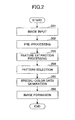
- FIG. 2 is a flowchart for explaining an image forming process performed by the image forming device according to the embodiment 1 of the present disclosure.
- image data of a DTP document in which raster image information, including photographic images, and vector image information, including line drawings, coexist in a mixed manner is input to the image forming device.
- FIG. 3A shows an example of an input image which is input to the image forming device by the image inputting unit 101.
- DTP image areas 301 and 302 which are generated by the DTP process are designated beforehand as objects by a user and input to the image forming device (step 201 in FIG. 2 ). These designated areas 301 and 302 are image areas that are to be filled with toner of a special color.
- FIG. 3B shows examples of filling patterns 303 and 304 which are formed to overlap the DTP image areas 301 and 302 respectively. These filling patterns have respective features that are different in tone, gloss, unevenness, etc.
- the pre-processing unit 102 resolution conversion, noise removal, color space conversion, and raster image selection of the input image; checking of the layer information of the input document; and checking of the registered patterns, etc., are carried out, so that the input image data are arranged in an image form suitable for the pre-processing (step 202 in FIG. 2 ).
- the resolution, the color space, etc., appropriate for the pre-processing may be prepared by experiment, or may be selected by the user.
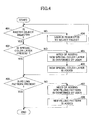
- FIG. 4 is a flowchart for explaining a process performed by the pre-processing unit 102 of the image forming device.
- a selection process in which only the raster information (raster object) is selected from the processing objects is performed.
- the pre-processing unit 102 determines whether a raster object is selected with respect to the input image data (step 401). When it is determined in step 401 that a vector image (vector object) is selected with respect to the input image data (NO in step 401), the process is transferred to step 404 in which an area (object) selection procedure is performed again by the user, because the vector image is not processed in this embodiment.
- step 401 When it is determined in step 401 that the raster object is selected with respect to the input image data, the process is transferred to step 402.
- step 402 the pre-processing unit 102 determines whether a special color layer is present in the layer information of the input document.
- the pre-processing unit 102 checks the layer information of the input document, and detects whether the special color layer which is used as the image area to be filled with the toner of the special color already exists in the input document.
- step 402 When it is determined in step 402 that the special color layer is not present, the process is transferred to step 405.
- the pre-processing unit 102 requests the user to confirm the need to newly generate an object (the special color layer) with a predetermined object name and a predetermined data structure.
- the pre-processing unit 102 adds the object (the special color layer) newly generated with the predetermined object name and the predetermined data structure to the layer information.
- step 403 the pre-processing unit 102 determines whether the registered filling pattern which is formed to overlap the image area is present in the input document. When it is determined in step 403 that the registered filling pattern is not present, the process is transferred to step 407. In step 407, the pre-processing unit 102 requests the user to confirm the need to add a new filling pattern to be registered in the filling pattern registering unit 105. Next, in step 408, the pre-processing unit 102 adds the newly registered filling pattern to the filling pattern registering unit 105.
- the feature extraction processing unit 103 of the image forming device computes the components of a predetermined feature vector based on the image information of a predetermined image area (step 203 in FIG. 2 ). For example, the feature extraction processing unit 103 computes feature quantities, including an average color (a primary moment) of pixels of the image area, a standard deviation (a square root of a secondary moment) of pixel values of the image area, and an edge amount of the image area. The feature extraction processing unit 103 uses one of the computed feature quantities or a combination of the computed feature quantities as a feature vector T extracted from the image area.
- FIG. 5 is a flowchart for explaining a process performed by the feature extraction processing unit 103 of the image forming device.
- the feature extraction processing unit 103 determines whether a 0-th moment is present in the computed feature quantities (step 501). When it is determined in step 501 that the 0-th moment is not present, the process is transferred to step 505. In step 505, the feature extraction processing unit 103 computes the 0-th moment.
- the feature extraction processing unit 103 determines whether the primary moment is present in the computed feature quantities (step 502). When it is determined in step 502 that the primary moment is not present, the process is transferred to step 506. In step 506, the feature extraction processing unit 103 computes the primary moment.
- the feature extraction processing unit 103 determines whether the secondary moment is present in the computed feature quantities (step 503). When it is determined in step 503 that the secondary moment is not present, the process is transferred to step 507. In step 507, the feature extraction processing unit 103 computes the secondary moment.
- step 504 the feature extraction processing unit 103 computes the edge quantity.
- the pattern selecting unit 104 searches the filling pattern registering unit 105 in which several predetermined feature vectors are registered, and selects, from among the registered feature vectors, a filling pattern having a feature vector most closely approximating the extracted feature vector T which is computed based on the image area by the feature extraction processing unit 103 (step 204 in FIG. 2 ).
- FIG. 6 is a diagram for explaining an example of the selection of the filling pattern using the feature vector.
- a feature extraction processing unit 604 (which includes a selection processing unit) extracts feature vectors V1 and V2 from image areas 602 and 603 designated within an input image 601, respectively.
- a filling pattern registering database (DB) 605 the relationship between feature vectors V and filling patterns P in specific image areas of the input image is registered beforehand.
- the selection processing unit 604 searches the filling pattern registering database (DB) 605 and selects filling patters P1 and P2 having feature vectors V1' and V2' which most closely approximate the extracted feature vectors V1 and V2, respectively.
- the selected filling patterns 607 and 608 are generated as clear color data 606.
- the pattern selecting unit 104 includes a distance computation processing unit and a pattern selection processing unit.
- the distance computation processing unit computes a distance between the feature vector computed based on the image area by the feature extraction processing unit 103 and the feature vector computed from the existing filling patterns. Generally, a distance between vectors can be determined by the inner product of the vectors.
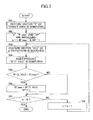
- FIG. 7 is a flowchart for explaining a distance computation process which is performed by the pattern selecting unit 104.
- n denotes the pattern number
- T denotes a feature vector of a target area
- N denotes the total number of the existing patterns
- V(n) denotes a feature vector of the n-th pattern
- TP_max denotes the maximum inner product
- SP denotes the selection pattern number.
- the computation of the feature vector T of the target area is performed by the feature extraction processing unit 103 as described above (step 701).
- the pattern selecting unit 104 searches for the feature vector of the n-th pattern V(n) in the filling pattern registering unit (DB) 105 (step 703), and computes the inner product IP (T, V (n)) (step 704).
- the pattern selecting unit 104 determines whether the inner product IP (T, V(n)) computed at step 704 is larger than the maximum inner product IP_max (step 705).
- the process is transferred to step 706.
- the IP_max is replaced by the computed inner product IP and the selection pattern number SP is also replaced by the n.
- the step 706 is not performed and the process is transferred to step 707.
- step 707 when it is determined in step 707 that the pattern number n is equal to the total number N, the process is terminated.
- a filling pattern having the feature vector most closely approximating the feature vector T of the target area can be selected from among all the existing filling patterns.
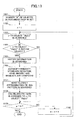
- FIG. 8 is a flowchart for explaining a pattern selection process performed by the pattern selecting unit 104.
- the pattern selecting unit 104 determines whether the automatic selection option is selected (step 801).
- step 801 When it is determined in step 801 that the automatic selection option is selected, the process is transferred to step 802, in which the above-mentioned distance computation is performed.
- step 803 the pattern selecting unit 104 automatically selects a filling pattern which has the shortest distance in the feature space (step 803).
- step 801 When it is determined in step 801 that the automatic selection option is not selected, the process is transferred to step 804.
- the pattern selecting unit 104 determines whether the preset pattern selection option is selected.
- the pattern selecting unit 104 searches the existing filling pattern registering database (DB) (step 805). Next, the pattern selecting unit 104 displays a list of available filling patterns (preset patterns) to the user (step 806), and receives a user's selection of a filling pattern from the displayed list of the available filling patterns (step 807). In this case, a list of the preset filling patterns may be displayed to the user for selection, or identification information, including a list of names of the respective present filling patterns, may be displayed to the user for selection.
- DB filling pattern registering database
- step 804 When it is determined in step 804 that the preset pattern selection option is not selected, the process is transferred to step 808.
- step 808 the pattern selecting unit 104 performs manual registration of a filling pattern selected by the user. In the manual registration, the pattern selecting unit 104 first performs a filling pattern registration procedure so that the user is prompted to register a filling pattern manually, and then automatically selects the registration result by the user as a registered filling pattern.
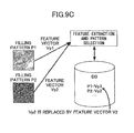
- FIGS. 9A-9C are diagrams for explaining the registration processing of filling patterns.
- feature vectors Vp1 and Vp2 are respectively extracted from filling patterns P1 and P2, and the feature vectors Vp1 and Vp2 are associated with the filling patterns P1 and P2 so that they are registered in a filling pattern registering database (DB).
- DB filling pattern registering database
- FIGS. 9B and 9C show the registration processing in a case in which a filling pattern in an area-2 of an image customized by the user as a filling pattern P2 is used for the registration.
- image data indicating "copy inhibition" is embedded in the area 2 of the image customized by the user.
- image data is subjected to a binarization process or the like, and the filling pattern P2 is generated as a result of the binarization process.
- a filling pattern for use in special color data such as clear data
- a feature vector associated with a filling pattern may be changed.
- the filling pattern P2 is to be associated with the feature vector Vp2 extracted from the filling pattern P2, and the filling pattern P2 is to be managed by using the filling pattern registering database (DB).
- DB filling pattern registering database
- the feature vector V2 extracted from the area-2 of the customized image is used as the feature vector associated with the filling pattern P2, instead of the feature vector Vp2 extracted from the filling pattern P2.
- the filling pattern registering unit 105 in order to generate a filling pattern from an arbitrary input image prepared by the user, includes a binarization processing unit, a replacement processing unit which replaces a feature vector extracted from a filling pattern by a feature vector computed from an image area of the input image designated by the user at the time of pattern registration, and a filling pattern registering database DB which is used by the replacement processing unit.
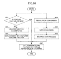
- FIG. 10 is a flowchart for explaining a process performed by the filling pattern registering unit 105.
- the filling pattern registering unit 105 performs a resolution conversion process which converts a resolution of an arbitrary input image into a predefined resolution (step 904), performs a size conversion process which converts a size of the input image into a pre-defined size (step 905), and performs the binarization process of the input image (step 906). Then, the process is transferred to step 907.
- the filling pattern registering unit 105 determines whether a feature vector computed from the input image is present (step 901). When it is determined in step 901 that the computed feature vector is not present, the process is transferred to step 902. In step 902, the filling pattern registering unit 105 computes the feature vector from the input image. Next, in step 903, the filling pattern registering unit 105 replaces the feature vector of the filling pattern by the computed feature vector. Then, the process is transferred to step 907. On the other hand, when it is determined in step 901 that the computed feature vector is present, the process is transferred to step 907.
- the filling pattern registering unit 105 performs the pattern registering process which registers the pattern image and the feature vector into the database DB (step 907).
- the special-color data generating unit 106 generates layer content information (step 205 in FIG. 2 ).
- the special-color data generating unit 106 manages special-color data as a unique layer that is independent of the input image information.
- the unique layer managed by the special-color data generating unit 106 may be prepared by the pre-processing unit 102.
- FIG. 11 is a flowchart for explaining a process performed by the special-color data generating unit 106.
- the special-color data generating unit 106 determines whether a layer of a special color is present (step 1001). When it is determined in step 1001 that the special color layer is not present, the special-color data generating unit 106 generates the special color layer (step 1002). When it is determined in step 1001 that the special color layer is present, the process is transferred to step 1003.
- step 1003 the special-color data generating unit 106 determines whether an object of the special color is present. When it is determined in step 1003 that the special color object is present, the process is transferred to step 1004. When it is determined in step 1003 that the special color object is not present, the process is terminated.
- step 1005 the special-color data generating unit 106 searches for a filling pattern associated with the object number On in the filling pattern registering database (DB).
- step 1006 the special-color data generating unit 106 sets the filling pattern (the searching result) in the property of the special-color object.
- image data of a DTP document in which raster image information, including photographic images, and vector image information, including line drawings, coexist in a mixed manner is input to the image forming device.
- a new layer of special color data is additionally provided in the image data of the DTP document, and the image formation unit 107 is controlled to form an image in which the special color data overlaps the image data of the selected area of the DTP document.
- a filling pattern which is appropriate for the special color expression is given to each of the objects which are present in the special color layer, respectively.
- the contents of the special color layer are respectively added to the input DTP image areas 301 and 302 shown in FIG. 3A , and an image in which the special color data overlaps the image data of the areas of the DTP image is formed.
- the image formation unit 107 uses the toners or inks of CMYK and a printing material, such as a special-color or transparent toner or ink, and forms such an image (as shown in FIG. 3B ) by performing the known electrophotographic or ink-jet printing process (step 206 in FIG. 2 ).
- the filling pattern appropriate for the area to be filled in is selected and the special-color data is generated, and the amount of the supplementary work concerning generation of the pattern data required to obtain the printing effect of the special color can be reduced and the working efficiency can be increased.
- the present embodiment is directed to a modification of the automatic selection of a filling pattern.
- FIG. 12 shows an example of a GUI (graphical user interface) in a case of the automatic selection.
- FIG. 13 is a flowchart for explaining the detailed process of the automatic selection according to the present embodiment.
- the pattern selecting unit 104 sets the total number N of objects contained in the document page (step 1101).
- the pattern selecting unit 104 searches for the n-th object "Obj(n)" (step 1103).
- the pattern selecting unit 104 determines whether the n-th object "Obj(n)" is a raster object (step 1104). When the result of the determination at step 1104 is negative (not a raster object), the process is transferred to step 1109. When the result of the determination at step 1104 is affirmative (a raster object), the process is transferred to step 1105.
- the pattern selecting unit 104 searches for the raster information of the n-th object "Obj(n)".
- the pattern selecting unit 104 computes the components of the target feature vector based on the raster information, including an average color or an average luminance of pixels of the raster object, a standard deviation of pixel values (luminance) of the raster object, and an edge amount of the raster object.
- the pattern selecting unit 104 searches, from among the feature vectors computed beforehand from the filling patterns, for a feature vector most closely approximating the target feature vector by using the most likelihood method (step 1107), and the pattern selecting unit 104 assigns the filling pattern to the object with the object number n in the document page (step 1108).
- the pattern selecting unit 104 uses the raster information thereof and determines the assignment of the filling pattern (step 1108).
- the most likelihood method is used (step 1107).
- another searching method different from the most likelihood method may be used.
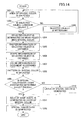
- FIG. 14 is a flowchart for explaining the process of generating a special-color data which is performed by the special-color data generating unit 106 according to the present embodiment.
- the process shown in FIG. 14 is similar to the process shown in FIG. 11 , therefore a duplicate description thereof will be omitted, and only the difference between the processes of FIG. 11 and FIG. 14 will be described.
- the raster information of the selected object is obtained (steps 1201-1207), and the special color pattern is selected based on the raster information (step 1208).
- the subsequent steps are processed.
- a two-dimensional LUT look-up table
- special color patterns "a", "b” and “c” may be predefined by considering the combination of the average luminance and the standard deviation of the luminances, and a corresponding one of the special color patterns can be associated with the selected object.
- one of the processes of generation of special-color data may be selectively performed based on the kind of the selected object.
- the selected object is a raster object
- an area having the shape that is the same as the shape of the selected object is generated and the special-color data is generated.
- the selected object is a vector object
- the processing in which the same-shape area is generated is not performed.
- the present embodiment is directed to a modification of the process of generating a special-color data.
- the printing effect of the special color is associated beforehand with each of the objects in the document page, so that the special color printing effect of the document page can be determined.
- FIG. 16 is a flowchart for explaining the process of generating the special-color data according to the present embodiment.
- the processing of FIG. 16 is performed by the special-color data generating unit 106 according to the present embodiment.
- the process shown in FIG. 16 is similar to the process shown in FIG. 11 , therefore a duplicate description thereof will be omitted, and only the difference between the processes of FIG. 11 and FIG. 16 will be described.
- each of the objects contained in the document data used in the DTP may have a property. Using this property, registering the printing effects in a printing effect list is possible.
- the printing effects (high gloss, gloss, etc.) of the respective objects are predefined (steps 1304 and 1305), one of the printing effects is assigned to the selected object (step 1306), and the special-color pattern is generated (step 1309).
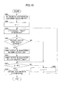
- the upper limit and the lower limit of a fixing temperature may be managed as metadata, and the fixing temperature of a document can be determined by detecting whether a common range in the fixing temperature exists for all the objects in the document. If a process for the case in which the common range does not exist is defined beforehand, the fixing temperature of a document including arbitrary objects can be predetermined. Similarly, if other printing-process parameters are managed as a metadata item of each object, the optimum parameter for the document can be determined.
- FIG. 17 is a flowchart for explaining a detailed process of the manual registration performed by the pattern selecting unit 104 (step 808 in FIG. 8 ).
- the user can use an arbitrary input image as the parameter for generating special-color data.
- the expression capability of a specific special color varies depending on the reproduction capability of the image forming device, and it is necessary to convert the user input image into a data format that can be reproduced by the image forming device, based on the information of the device configuration.
- the pattern selecting unit 104 obtains the device configuration information of the image forming device via a network and searches for constraints in the device configuration information.
- the pattern selecting unit 104 causes the user to input the index data (for example, a printing effect name) of a new filling pattern to be registered (step 1401).
- the pattern selecting unit 104 causes the user to select the input image data (step 1402).
- the input image data any of color image data, gray-level image data and binary image data may be selected.
- the pattern selecting unit 104 converts the input image data into a binary image expression by using an appropriate converting method (step 1408).
- the pattern selecting unit 104 uses the input image data as a filling pattern without change.
- the binarization method of the gray-level image for example a simple binarization using a fixed threshold, or an adaptive binarization method commonly used in document image processing may be used.
- a method using a median value of pixel values of the input image as a threshold may be used.
- the pattern selecting unit 104 converts the input image data into a gray-level image expression (step 1407).
- the pattern selecting unit 104 computes the feature vector as described above by using the image information of a specific area of the input image separately designated (step 1409). It is assumed that "A" denotes the feature vector computed. Next, the pattern selecting unit 104 replaces the feature vector computed from the filling pattern by this feature vector A, and uses the feature vector A as a feature vector of the filling pattern concerned (step 1410).
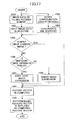
- FIG. 18 is a flowchart for explaining a detailed procedure of the step 1403 of FIG. 17 .
- the process shown in FIG. 18 is similar to the process shown in FIG. 17 , therefore a duplicate description thereof will be omitted, and only the difference between the processes of FIG. 17 and FIG. 18 will be described.
- the pattern selecting unit 104 obtains a resolution "R” and a size "S” of the special color data that can be reproduced by the image forming device (step 1504), and compares the resolution "R” and size "S” with the resolution "r” and size “s” of the input image designated by the user, respectively (steps 1507 and 1512). Based on the comparison results, the pattern selecting unit 104 performs the resolution conversion of the input image (step 1508), and a clipping process of the input image (step 1513) or a tiling process of the input image (step 1514).
- the pattern selecting unit 140 converts the resolution “r” of the input image into “R” and uses "R” as the resolution of the input image (step 1508).
- the pattern selecting unit 140 obtains the number of tones per pixel (the number of bits) which can be reproduced by the image forming device (step 1504). Based on the comparison result, the pattern selecting unit 140 performs the binary image expression of the special-color data (step 1511) or the gray-level image expression of the special-color data (step 1510).
- the pattern selecting unit 140 performs the clipping process of the input image so as to suit the size of the image area concerned (step 1513).
- the pattern selecting unit 140 performs the tiling process in which two or more input images are pasted, so as to adjust the size of the filling pattern according to the size of the image area concerned (step 1514).
- another method such as scaling of the input image, may be used in any case.
- the present embodiment is directed to the printing effect of the special color.
- the printing effects are designated for the objects in the document by the user, respectively. It is determined whether the designated printing effects of the objects are conformable. If there is a mismatching printing effect, the mismatch is corrected by replacing the mismatching printing effect with a similar printing effect. If the replacement is impossible, the user may be notified of it and may be requested to designate a new printing effect again.
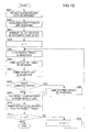
- FIG. 19 is a flowchart for explaining a process of generating a special-color data which is performed by the special-color data generating unit 106 according to the present embodiment.
- the device configuration data of the image forming device is obtained (step 1601), and the available special color printing effect is searched for (step 1602).
- the printing effect designated for the n-th object "Obj(n)" in the document is obtained (step 1606).
- the special-color data generating unit 106 searches the printing effect list (step 1607), and determines whether there is any printing effect of an object in the same document page which conflicts with the obtained printing effect (step 1608). When the conflict occurs, the special-color data generating unit 106 searches for a predefined similar printing effect and replaces the obtained printing effect with the similar printing effect (step 1609).
- the special-color data generating unit 106 registers the printing effect of the n-th object into the printing effect list (step 1610).
- the printing effect is assigned to the n-th object (step 1611).
- the above procedure of steps 1605-1611 is repeatedly performed for all the objects in the document, and the special-color data is generated.
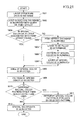
- FIG. 20 is a flowchart for explaining a modification of the special-color data generating process according to the present embodiment.
- the process shown in FIG. 12 is similar to the process shown in FIG. 16 , therefore a duplicate description thereof will be omitted, and only the difference between the processes of FIG. 16 and FIG. 20 will be described.
- the priority relationship of the printing effects of the object-1 and the object-2 is obtained (step 1706).
- the special-color data generating unit 106 corrects the printing effect of the object-1 (step 1708). For example, when the area (object-2) overlaps the area (object-1), priority is given to applying the filling pattern to the area (object-2).
- the present embodiment is directed to a process in which the pattern filling is performed using only a special color pattern (a selected special color pattern) associated with a specific printing effect.
- FIG. 21 is a flowchart for explaining a process performed by the special-color data generating unit 106 according to the present embodiment.
- the special-color data generating unit 106 obtains the layer structure data of the document (step 1801), and searches the layer structure database (DB) by setting the printing effect as a query (step 1802).
- the special-color data generating unit 106 searches the printing effect database (DB) shown in FIG. 22A (step 1804), determines the layer to be filled and the selected special color pattern (steps 1805 and 1806), and generates the special color layer (step 1807).
- DB printing effect database
- the special-color data generating unit 106 causes the user to select the special color area (step 1808).
- the special-color data generating unit 106 replaces the currently used special color pattern with the selected special color pattern (step 1811) and generates the special-color data (step 1812).
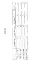
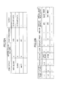
- FIG. 22A shows an example of a printing effect database which is searched by the special-color data generating unit 106.
- the special-color patterns associated with the printing effects such as high gloss, gloss, and matt, are set up beforehand.
- the matt of FIG. 22A means a printing effect which is formed by a halftone dot pattern with a high frequency and the gloss is lost.
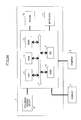
- FIG. 22B shows an example of data items of the layers being used.
- the layer name is used to distinguish each layer. After uniqueness of the name of each layer given as an initial value by the system is secured, the user may change freely the layer name.
- the layer class indicates the order of overlapping of the effect at the time of printing or displaying in the DTP.
- the object is used to manage the ID of the object contained in each layer. Fundamentally, one object belongs to one layer.
- the color indicates a display color used when the object is displayed in the display screen of the DTP.
- the lock indicates the permission of writing or correction to the layer concerned, in order to protect the content.
- the lock that is set to 0 indicates an unlocked state, and the lock that is set to 1 indicates a locked state.
- the display indicates the permission of the screen displaying in the DTP.
- the display that is set to 0 indicates that the screen displaying is not permitted, and the display that is set to 1 indicates that the screen displaying is permitted.
- the print is a flag indicating whether the layer concerned is to be used for printing.
- the print that is set to 1 indicates that the layer is to be used for printing, and the print that is set to 0 indicates that the layer is not to be used for printing.
- the preview is a flag indicating whether a preview reflects a change of the content of a display immediately.
- the preview that is set to 0 indicates that the preview does not reflect the change, and the preview that is set to 1 indicates that the preview reflects the change.
- the display density indicates the density of a display of the object by the display color.
- the special color printing effect is text information that indicates which printing effect or white special color toner of the special color printing each layer is associated with.
- FIG. 22A An example of the database which manages the relationship between the layers and the printing effects used in the present embodiment is shown in FIG. 22A .
- the special color pattern, the presence of post-processing, and the information of the layer to be filled with the special color data are associated and managed.
- the process shown in FIG. 21 may be modified so that, in order to restrict the layers to be filled only to the layers associated with the special color printing effects, other layers different from the layers associated with the special color printing effects are set in a locked state.
- FIG. 23 is a flowchart for explaining such a process.
- the process shown in FIG. 23 is similar to the process shown in FIG. 21 , therefore a duplicate description thereof will be omitted, and only the difference between the processes of FIG. 21 and FIG. 23 will be described.
- steps 1941-1947 is the same as the processing of steps 1841-1847 of FIG. 21 , and the processing of steps 1908 and 1909 of FIG. 23 is newly added.
- the special color printing effect may be expressed in the document regardless of the kind of the layer to be filled.
- a demerit such as a reduction of readability, may take place.
- the system is configured to ensure that the information of the special color is written only to the special color layer.
- the special-color data generating unit 106 sets other layers than the layer to be filled (the special color layer) in a locked state (step 1908), and sets the layer to be filled (the special color layer) in a selected state (step 1909). Hence, it is possible to prevent the writing of the special color information to the layers other than the special color layer at the time of writing in the processing of subsequent steps 1808-1812 in the process of FIG. 21 .
- the parameters of the printing process and the post-processing process required for the special color printing are associated with the printing effects, and the parameters associated with the printing effects are managed. This can be realized using the printing effect database shown in FIG. 22A .
- the special color patterns in FIG. 22A are unique special color patterns indicating the printing effects. For example, swatches commonly used in Adobe Illustrator (registered trademark) may be used as the special color patterns.
- the column of the post-processing in the printing effect database indicates the use of a glosser for increasing the gloss level of the paper surface, for example.
- the column of the layer in the printing effect database indicates the layer to which the special color pattern is written.
- the special color pattern may be written to the layer only, and may be written to another layer.
- the patterns as shown in FIG. 3B may be used. These patterns differ in tone, a feeling of gloss, a feeling of unevenness, a feeling of touch, etc., therefore it is necessary to conduct a preliminary experiment using the actual printing process in order to check the printing effects, so that the printing effects are associated with the above-described printing effects.
- FIG. 24 shows the hardware composition of an image processing device in which the image forming device according to the present disclosure is implemented by software.
- the image processing device 1 includes a program reader device 1a, a CPU 1b to control the whole image processing device, a RAM 1c used as a work area of the CPU 1b, a ROM 1d to store a control program of the CPU 1b, a hard disk drive 1e, an NIC 1f to communicate with an external device via a network, a mouse 1g, a keyboard 1h, a display 2 to display image data and receive input data when the display screen is touched directly by the user, and an image forming device 3, such as a color printer.
- the image processing device 1 shown in FIG. 24 may be constructed by, for example, a workstation, a personal computer, etc.
- the functions of the pre-. processing unit, the feature extraction processing unit, the pattern selecting unit, and the special-color data generating unit, as shown in FIG. 1 may be incorporated in the CPU 1b.
- the memory units including the RAM 1c, the ROM 1d, and the hard disk 1e, may be used.
- the processing functions performed by the CPU 1b may be provided by a software package or an information recording medium, such as a CD-ROM or a magnetic disk.
- a disk drive unit (not shown) which accesses an information recording medium when the recording medium is set is also provided.
- the image forming method of the present disclosure can be carried out by a general-purpose computer system including a display, in which a control program stored in the information recording medium, such as a CD-ROM, is installed.
- the control program when executed by the CPU of the computer system, causes the CPU to perform the image forming method of the present disclosure.
- the program for performing the image forming method of the present disclosure may be offered in a state in which the program is recorded on the recording medium.
- the information recording medium in which the control program is stored is not limited to the CD-ROM.
- a ROM, a RAM, a flash memory, a magneto-optical disk, etc. may be used instead.
- the control program stored in the information recording medium is installed into the hard disk 1e, and the program is loaded in the RAM 1c and executed by the CPU 1b so that the image-processing functions are carried out.
- the amount of the supplementary work concerning generation of the pattern data required to obtain the printing effect of a special color can be reduced, and the working efficiency can be increased.
Landscapes
- Physics & Mathematics (AREA)
- General Physics & Mathematics (AREA)
- Engineering & Computer Science (AREA)
- Microelectronics & Electronic Packaging (AREA)
- Image Processing (AREA)
- Facsimile Image Signal Circuits (AREA)
- Editing Of Facsimile Originals (AREA)
- Accessory Devices And Overall Control Thereof (AREA)
- Color, Gradation (AREA)
- Control Or Security For Electrophotography (AREA)
- Color Electrophotography (AREA)
- Color Image Communication Systems (AREA)
Applications Claiming Priority (1)
| Application Number | Priority Date | Filing Date | Title |
|---|---|---|---|
| JP2012043905A JP2013182027A (ja) | 2012-02-29 | 2012-02-29 | 画像形成装置、画像形成方法、プログラムおよび記録媒体 |
Publications (2)
| Publication Number | Publication Date |
|---|---|
| EP2634637A2 true EP2634637A2 (de) | 2013-09-04 |
| EP2634637A3 EP2634637A3 (de) | 2017-11-08 |
Family
ID=47884132
Family Applications (1)
| Application Number | Title | Priority Date | Filing Date |
|---|---|---|---|
| EP13156515.2A Withdrawn EP2634637A3 (de) | 2012-02-29 | 2013-02-25 | Bilderzeugungsvorrichtung, Bilderzeugungsverfahren und Aufzeichnungsmedium |
Country Status (3)
| Country | Link |
|---|---|
| US (1) | US20130222817A1 (de) |
| EP (1) | EP2634637A3 (de) |
| JP (1) | JP2013182027A (de) |
Families Citing this family (11)
| Publication number | Priority date | Publication date | Assignee | Title |
|---|---|---|---|---|
| JP2014164656A (ja) | 2013-02-27 | 2014-09-08 | Ricoh Co Ltd | 画像処理方法およびプログラム |
| JP6252120B2 (ja) | 2013-11-12 | 2017-12-27 | 株式会社リコー | 情報処理装置およびプログラム |
| US10043104B2 (en) * | 2015-01-05 | 2018-08-07 | Avigilon Fortress Corporation | Automatic moving object verification |
| US9967433B2 (en) * | 2015-07-06 | 2018-05-08 | Canon Kabushiki Kaisha | Generating print data including data to form a flat and smooth color development layer and data to form a gloss layer |
| JP6540615B2 (ja) * | 2016-06-30 | 2019-07-10 | 京セラドキュメントソリューションズ株式会社 | 画像形成装置 |
| US10015504B2 (en) * | 2016-07-27 | 2018-07-03 | Qualcomm Incorporated | Compressing image segmentation data using video coding |
| JP6977480B2 (ja) * | 2017-10-30 | 2021-12-08 | 富士フイルムビジネスイノベーション株式会社 | 情報処理装置、および情報処理プログラム |
| CN109976121B (zh) * | 2017-12-27 | 2021-12-21 | 株式会社理光 | 图像形成装置以及印刷品 |
| JP2020154892A (ja) * | 2019-03-20 | 2020-09-24 | 株式会社リコー | 情報処理装置及び情報処理プログラム |
| US11341383B2 (en) * | 2019-08-18 | 2022-05-24 | Kyocera Document Solutions Inc. | Methods and apparatus to detect effective tiling area and fill tiles efficiently |
| JP7358917B2 (ja) * | 2019-10-31 | 2023-10-11 | 株式会社リコー | 印刷システム、プログラム、画像形成装置、及び、印刷方法 |
Citations (2)
| Publication number | Priority date | Publication date | Assignee | Title |
|---|---|---|---|---|
| JP2008145453A (ja) | 2006-12-05 | 2008-06-26 | Canon Inc | 画像形成システムおよび画像形成装置 |
| JP2008532066A (ja) | 2005-02-22 | 2008-08-14 | イーストマン コダック カンパニー | 電子写真画像のテクスチャ生成 |
Family Cites Families (9)
| Publication number | Priority date | Publication date | Assignee | Title |
|---|---|---|---|---|
| US5552903A (en) * | 1991-05-01 | 1996-09-03 | Canon Kabushiki Kaisha | Image processing apparatus and image processing method |
| JPH10187951A (ja) * | 1996-12-27 | 1998-07-21 | Namco Ltd | 画像合成装置及び画像合成方法 |
| JP4732031B2 (ja) * | 2005-06-30 | 2011-07-27 | キヤノン株式会社 | 画像処理装置及び画像処理方法及びコンピュータプログラム |
| JP4979498B2 (ja) * | 2007-07-26 | 2012-07-18 | キヤノン株式会社 | 画像処理装置、画像処理方法 |
| FR2935579B1 (fr) * | 2008-08-28 | 2010-11-05 | Centre Nat Etd Spatiales | Procede d'acquisition, de reduction et de transmission d'images satellitaires |
| JP2011081278A (ja) * | 2009-10-09 | 2011-04-21 | Canon Inc | 画像形成装置およびシステム |
| JP5531836B2 (ja) * | 2009-11-10 | 2014-06-25 | 株式会社リコー | 画像処理装置及びプログラム |
| JP5495802B2 (ja) * | 2010-01-06 | 2014-05-21 | キヤノン株式会社 | 画像処理装置、画像処理装置の制御方法、および、プログラム |
| JP5794062B2 (ja) * | 2010-09-15 | 2015-10-14 | 株式会社リコー | 情報処理装置、データ生成方法及びプログラム |
-
2012
- 2012-02-29 JP JP2012043905A patent/JP2013182027A/ja active Pending
-
2013
- 2013-02-25 EP EP13156515.2A patent/EP2634637A3/de not_active Withdrawn
- 2013-02-28 US US13/780,057 patent/US20130222817A1/en not_active Abandoned
Patent Citations (2)
| Publication number | Priority date | Publication date | Assignee | Title |
|---|---|---|---|---|
| JP2008532066A (ja) | 2005-02-22 | 2008-08-14 | イーストマン コダック カンパニー | 電子写真画像のテクスチャ生成 |
| JP2008145453A (ja) | 2006-12-05 | 2008-06-26 | Canon Inc | 画像形成システムおよび画像形成装置 |
Also Published As
| Publication number | Publication date |
|---|---|
| EP2634637A3 (de) | 2017-11-08 |
| US20130222817A1 (en) | 2013-08-29 |
| JP2013182027A (ja) | 2013-09-12 |
Similar Documents
| Publication | Publication Date | Title |
|---|---|---|
| US20130222817A1 (en) | Image forming device, image forming method, and recording medium | |
| US20110110590A1 (en) | Apparatus, system, and method of image processing | |
| US8477376B2 (en) | System to enable development of clear toner forms | |
| US8139263B2 (en) | Systems and methods for printing artwork containing overlapped inks | |
| CN111343359A (zh) | 信息处理装置和存储介质 | |
| KR20180087842A (ko) | 화상 처리 장치 및 그 제어 방법 | |
| US8331612B2 (en) | Method and system for document annotation that includes outlining | |
| CN103856680A (zh) | 图像处理装置、以及图像处理装置的控制方法 | |
| US8982418B2 (en) | Printing system, a printing method, and a computer program for performing color conversion on a print object | |
| CN112000303A (zh) | 可实现水印打印的处理方法、装置、电子设备和存储介质 | |
| US9036202B2 (en) | Image processing device and image processing method performing image process according to attribute information of image object | |
| US20080079977A1 (en) | Electronic format file content sensitive user interface | |
| US8582188B2 (en) | Spot color press emulation color transformation method and system | |
| US20080180727A1 (en) | Print workflow methods and printing system apparatuses | |
| JP4804443B2 (ja) | 判断画像印刷元データ生成装置 | |
| US8335344B2 (en) | Method and system for document annotation | |
| US11418683B1 (en) | System and method for defining colorant values for printing on colored print media | |
| US10038824B1 (en) | Partitioning raster images for multiple print colorant orders | |
| US10432826B2 (en) | Automatic suppression of unrecognized spot colors from a raster image | |
| US9001381B2 (en) | Image forming apparatus which processes printing data including a transparency pattern, printing control terminal apparatus, and image forming method thereof | |
| US20080079976A1 (en) | Electronic format file content sensitive user interface | |
| US7986436B2 (en) | Image processing apparatus and method | |
| JP2005269641A (ja) | データ変換方法及び印刷指示方法 | |
| EP2860956B1 (de) | Verfahren zur Umwandlung von Druckdaten in ein Rasterbild | |
| US9317229B2 (en) | Finishing compatibility evaluation |
Legal Events
| Date | Code | Title | Description |
|---|---|---|---|
| PUAI | Public reference made under article 153(3) epc to a published international application that has entered the european phase |
Free format text: ORIGINAL CODE: 0009012 |
|
| 17P | Request for examination filed |
Effective date: 20130225 |
|
| AK | Designated contracting states |
Kind code of ref document: A2 Designated state(s): AL AT BE BG CH CY CZ DE DK EE ES FI FR GB GR HR HU IE IS IT LI LT LU LV MC MK MT NL NO PL PT RO RS SE SI SK SM TR |
|
| AX | Request for extension of the european patent |
Extension state: BA ME |
|
| PUAL | Search report despatched |
Free format text: ORIGINAL CODE: 0009013 |
|
| AK | Designated contracting states |
Kind code of ref document: A3 Designated state(s): AL AT BE BG CH CY CZ DE DK EE ES FI FR GB GR HR HU IE IS IT LI LT LU LV MC MK MT NL NO PL PT RO RS SE SI SK SM TR |
|
| AX | Request for extension of the european patent |
Extension state: BA ME |
|
| RIC1 | Information provided on ipc code assigned before grant |
Ipc: G03G 15/00 20060101AFI20170929BHEP |
|
| STAA | Information on the status of an ep patent application or granted ep patent |
Free format text: STATUS: THE APPLICATION IS DEEMED TO BE WITHDRAWN |
|
| 18D | Application deemed to be withdrawn |
Effective date: 20180509 |