EP2634651A2 - Roulement à billes et procédé de fabrication - Google Patents
Roulement à billes et procédé de fabrication Download PDFInfo
- Publication number
- EP2634651A2 EP2634651A2 EP13156200.1A EP13156200A EP2634651A2 EP 2634651 A2 EP2634651 A2 EP 2634651A2 EP 13156200 A EP13156200 A EP 13156200A EP 2634651 A2 EP2634651 A2 EP 2634651A2
- Authority
- EP
- European Patent Office
- Prior art keywords
- lip
- balls
- ball bearing
- inner ring
- retaining ring
- Prior art date
- Legal status (The legal status is an assumption and is not a legal conclusion. Google has not performed a legal analysis and makes no representation as to the accuracy of the status listed.)
- Granted
Links
- 238000004519 manufacturing process Methods 0.000 title description 4
- 238000000034 method Methods 0.000 claims abstract description 9
- 230000000284 resting effect Effects 0.000 claims abstract 2
- 238000004804 winding Methods 0.000 claims description 11
- 230000015572 biosynthetic process Effects 0.000 claims description 2
- 238000002788 crimping Methods 0.000 description 6
- 238000005096 rolling process Methods 0.000 description 3
- 230000008646 thermal stress Effects 0.000 description 2
- 238000003466 welding Methods 0.000 description 2
- 229910000831 Steel Inorganic materials 0.000 description 1
- 238000004026 adhesive bonding Methods 0.000 description 1
- 239000000463 material Substances 0.000 description 1
- 230000010355 oscillation Effects 0.000 description 1
- 238000002360 preparation method Methods 0.000 description 1
- 125000006850 spacer group Chemical group 0.000 description 1
- 239000010959 steel Substances 0.000 description 1
- 230000035882 stress Effects 0.000 description 1
- 239000000725 suspension Substances 0.000 description 1
- 230000001131 transforming effect Effects 0.000 description 1
Images

Classifications
-
- G—PHYSICS
- G04—HOROLOGY
- G04B—MECHANICALLY-DRIVEN CLOCKS OR WATCHES; MECHANICAL PARTS OF CLOCKS OR WATCHES IN GENERAL; TIME PIECES USING THE POSITION OF THE SUN, MOON OR STARS
- G04B31/00—Bearings; Point suspensions or counter-point suspensions; Pivot bearings; Single parts therefor
- G04B31/004—Bearings; Point suspensions or counter-point suspensions; Pivot bearings; Single parts therefor characterised by the material used
- G04B31/012—Metallic bearings
- G04B31/0123—Metallic bearings with metallic ball bearings and metallic roller bearings
-
- F—MECHANICAL ENGINEERING; LIGHTING; HEATING; WEAPONS; BLASTING
- F16—ENGINEERING ELEMENTS AND UNITS; GENERAL MEASURES FOR PRODUCING AND MAINTAINING EFFECTIVE FUNCTIONING OF MACHINES OR INSTALLATIONS; THERMAL INSULATION IN GENERAL
- F16C—SHAFTS; FLEXIBLE SHAFTS; ELEMENTS OR CRANKSHAFT MECHANISMS; ROTARY BODIES OTHER THAN GEARING ELEMENTS; BEARINGS
- F16C33/00—Parts of bearings; Special methods for making bearings or parts thereof
- F16C33/30—Parts of ball or roller bearings
- F16C33/58—Raceways; Race rings
- F16C33/60—Raceways; Race rings divided or split, e.g. comprising two juxtaposed rings
-
- F—MECHANICAL ENGINEERING; LIGHTING; HEATING; WEAPONS; BLASTING
- F16—ENGINEERING ELEMENTS AND UNITS; GENERAL MEASURES FOR PRODUCING AND MAINTAINING EFFECTIVE FUNCTIONING OF MACHINES OR INSTALLATIONS; THERMAL INSULATION IN GENERAL
- F16C—SHAFTS; FLEXIBLE SHAFTS; ELEMENTS OR CRANKSHAFT MECHANISMS; ROTARY BODIES OTHER THAN GEARING ELEMENTS; BEARINGS
- F16C43/00—Assembling bearings
- F16C43/04—Assembling rolling-contact bearings
-
- F—MECHANICAL ENGINEERING; LIGHTING; HEATING; WEAPONS; BLASTING
- F16—ENGINEERING ELEMENTS AND UNITS; GENERAL MEASURES FOR PRODUCING AND MAINTAINING EFFECTIVE FUNCTIONING OF MACHINES OR INSTALLATIONS; THERMAL INSULATION IN GENERAL
- F16C—SHAFTS; FLEXIBLE SHAFTS; ELEMENTS OR CRANKSHAFT MECHANISMS; ROTARY BODIES OTHER THAN GEARING ELEMENTS; BEARINGS
- F16C19/00—Bearings with rolling contact, for exclusively rotary movement
- F16C19/02—Bearings with rolling contact, for exclusively rotary movement with bearing balls essentially of the same size in one or more circular rows
- F16C19/14—Bearings with rolling contact, for exclusively rotary movement with bearing balls essentially of the same size in one or more circular rows for both radial and axial load
- F16C19/16—Bearings with rolling contact, for exclusively rotary movement with bearing balls essentially of the same size in one or more circular rows for both radial and axial load with a single row of balls
- F16C19/163—Bearings with rolling contact, for exclusively rotary movement with bearing balls essentially of the same size in one or more circular rows for both radial and axial load with a single row of balls with angular contact
- F16C19/166—Four-point-contact ball bearings
-
- F—MECHANICAL ENGINEERING; LIGHTING; HEATING; WEAPONS; BLASTING
- F16—ENGINEERING ELEMENTS AND UNITS; GENERAL MEASURES FOR PRODUCING AND MAINTAINING EFFECTIVE FUNCTIONING OF MACHINES OR INSTALLATIONS; THERMAL INSULATION IN GENERAL
- F16C—SHAFTS; FLEXIBLE SHAFTS; ELEMENTS OR CRANKSHAFT MECHANISMS; ROTARY BODIES OTHER THAN GEARING ELEMENTS; BEARINGS
- F16C2370/00—Apparatus relating to physics, e.g. instruments
Definitions
- the present invention relates to a ball bearing for supporting and guiding in rotation an object of small dimensions.
- this invention relates to a ball bearing that can be used in a watch movement, for example to support and guide an oscillating weight of an automatic winding device, or a component of the gear train, a balance, an indicator or any other rotary element.
- Ball bearings are used in many applications in which it is desired to support and guide a part accurately by reducing friction.
- several uses of ball bearings are known, in particular in the suspension of the oscillating masses of the mechanical winding movements.
- the documents FR2886995 and US2005196087 describe bearings for a self-winding watch oscillating weight in which the balls roll between two rings each having two conical surfaces.
- the assembly of the components of known ball bearings is delicate.
- the relative positioning of the conical surfaces must be perfect to allow frictionless rotation of the balls.
- the balls rotate between an outer ring, having two conical surfaces facing each other, and an inner ring composed of two separate elements, each forming a conical surface. for the rolling of the balls, and which are joined together only after the positioning of the balls and the spacer cage.
- the fixing of the two elements of the inner ring is carried out, for example, by welding, gluing or by their tight fit, and its accuracy depend significantly on the characteristics of the assembled bearing. All known assembly techniques include mechanical and / or thermal stresses that are difficult to completely control, and negatively influence the accuracy and friction of the bearings thus obtained.
- Bearings are known in which a ring comprises two elements assembled by laser welding. This technique, however, involves additional steps of surface preparation, and contributes greatly to the production costs of the bearing.
- An object of the present invention is to provide an assembled bearing with a simpler and more reliable technique of known assembly methods.
- Another object of the invention is to provide a more precise bearing and more economical production of known bearings.
- the objects of the invention are also achieved by a method of assembling a bearing comprising the steps listed in the preamble of claim 6 and in which a circular lip of the inner ring body is deformed in order to secure a retaining ring. .
- the Fig. 1 illustrates, very schematically and simplified, an automatic winding device for use in a wristwatch.
- the oscillating mass 30 is supported by a ball bearing 35 fixed on the movement, for example screwed on a board or automatic bridge.
- the movements of the carrier cause oscillation causing the oscillating mass 30 which is free to rotate about the axis of the bearing 35.
- the pinion 60 integral with the oscillating mass 30 rotates a rectifying system shown schematically on the figure 1 by the two rectifying mobiles 32.
- a rectifying system shown schematically on the figure 1 by the two rectifying mobiles 32.
- ratchet wheels, sliding gears, one-way clutches or inverters capable of transforming the movement in both directions of the oscillating mass into a unidirectional winding movement, employing for example ratchet wheels, sliding gears, one-way clutches or inverters, in which the winding takes place in only one, or in both directions of rotation of the mass 30. All these variants are usable in the context of the invention.
- the rectifier unit 32 is followed by a reduction gear train comprising the reduction units 33 in order to reduce the initial speed of the mass 30 and to increase the torque intended for the winding of the mainspring by the ratchet 38.
- This part can also include all the variants known in the watchmaking art, such as automatic clutches to allow manual winding, etc., without departing from the scope of the invention.
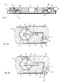
- the Fig. 2 represents a section of the bearing 35 along the plane AA of the preceding figure.
- the bearing comprises an outer ring 49, for example made of steel, inside which are machined two surfaces 51, 52, conical in the example of Figures 2 to 4 , facing one another.
- the surfaces 51, 52 form a groove in which the spherical balls 45 roll; seven balls are typically used for a bearing for a large size automatic watch, and five balls for small automatic movements, but the number of balls may vary beyond these limits.
- the cage 48 has the function of keeping the balls 45 apart during the rotation.
- the surfaces 51 and 52 are preferably symmetrical with respect to the horizontal bearing plane of the bearing, and their axis of revolution substantially coincides with the axis 36 of the bearing.
- the angle between the surfaces 51 and 52 is typically 90 °, but other values and arrangements are also possible.
- an inner ring body which has a surface 53 coaxial with the surfaces 51 and 52 and which is also supported on the balls 45.
- the fourth running surface 54 and provided by a retaining ring 42 separate from the inner ring body 40 to allow the assembly of the bearing.
- the surfaces 53, 54 are also conical, and the inner ring body 40 also carries the holes 41 which can accommodate screws for fixing the bearing 35 in a clockwork movement, for example.
- the inner ring body 40 is placed concentrically inside the outer ring 49, and the cage 48 and the balls 45 are inserted into the space between the rings. , by the open space left by the retaining ring 42, which is not yet present, so that the balls touch the three surfaces 51, 52, 53.
- the retaining ring 42 is then placed around the inner ring body until it bears on the balls 45 by its surface 54, preferably with a predetermined bearing force.
- the balls 45 thus have four points of contact with the surfaces 51-54.
- the Figures 3a and 3b illustrate an enlargement of the elements surrounded by the circle B of the figure 2 .
- the inner ring body has a circular groove 20 which forms a circular lip 22 adjacent to the diameter on which the retaining ring 42 engages.
- the retaining ring 42 preferably has a shoulder 41 on the corresponding diameter.
- the assembly of the bearing is completed by deforming the lip 22 against the cylindrical surface 46 of the retaining ring and against the shoulder 41. This crimping operation secures the retaining ring 42 and the inner ring body 40 in an unmountable manner and precise.
- the deformation of the lip 22 is performed using a crimping tool 70 visible on the figure 3b .
- the tool is for example a ring designed to slide around the retaining ring 42 and having an inclined surface 73 which pushes the lip 22 towards the outside against the surface 46 and axially against the shoulder 41.
- the lip 22 may also take the form of a crenellated edge allowing the formation of foldable legs (not shown) able to bear against the cylindrical surface 46 of the retaining ring and against the shoulder 41 during the operation of crimping.
- the crimping tool 70 can be arranged so as to come to push the lip 22 only on the flaps foldable.
- Such an arrangement has the advantage that a lower force can be exerted on the crimping tool 70.
- the assembly method of the invention makes it possible to perfectly control the contact force between the balls 45 and the rolling surfaces. 51-54, without causing mechanical and thermal stress, harmful to precision. It has the advantage of being feasible in an industrial environment with a particularly simple tooling and is therefore suitable for mass production of miniaturized ball bearings for the watch industry or for other applications of precision micromechanics.
Landscapes
- Engineering & Computer Science (AREA)
- General Engineering & Computer Science (AREA)
- Mechanical Engineering (AREA)
- Physics & Mathematics (AREA)
- General Physics & Mathematics (AREA)
- Rolling Contact Bearings (AREA)
- Support Of The Bearing (AREA)
- Heat Treatment Of Articles (AREA)
Abstract
Description
- La présente invention concerne un roulement à billes pour supporter et guider en rotation un objet de petites dimensions. Notamment, mais pas exclusivement, cette invention concerne un roulement à billes utilisable dans un mouvement horloger, par exemple pour supporter et guider une masse oscillante d'un dispositif de remontage automatique, ou un élément du rouage, un balancier, un indicateur ou tout autre élément rotatif.
- Les roulements à billes sont utilisés en maintes applications dans lesquelles on souhaite supporter et guider en rotation avec précision une pièce en réduisant le frottement. Dans la technique horlogère, on connaît plusieurs emplois des roulements à billes, notamment dans la suspension des masses oscillantes des mouvements à remontage mécanique. Les documents
FR2886995 US2005196087 décrivent des roulements pour une masse oscillante de montre à remontage automatique, dans lesquels les billes roulent entre deux bagues présentant chacune deux surfaces coniques. - L'assemblage des composants des roulements à billes connus est délicat. Le positionnement relatif des surfaces coniques doit être parfait pour permettre une rotation sans frottement des billes. Dans la plupart des roulements à bille utilisés dans la technique horlogère, les billes tournent entre une bague extérieure, présentant deux surfaces coniques en regard l'une de l'autre, et une bague intérieure composée de deux éléments séparés, chacun formant une surface conique pour le roulement des billes, et qui sont solidarisés entre eux seulement après le positionnement des billes et de la cage d'espacement. La fixation des deux éléments de la bague intérieure est réalisée, par exemple, par soudage, collage ou par leur ajustement serré, et de sa précision dépendent de façon importante les caractéristiques du roulement assemblé. Toutes les techniques d'assemblage connues comportent des stress mécaniques et/ou thermiques qui sont difficiles à maitriser complètement, et influencent négativement la précision et le frottement des roulements ainsi obtenus.
- On connaît des roulements dans lesquels une bague comporte deux éléments assemblés par soudage laser. Cette technique comporte toutefois des étapes supplémentaires de préparation des surfaces, et contribue fortement aux coûts de production du roulement.
- Un but de la présente invention est de proposer un roulement assemblé avec une technique plus simple et plus fiable des procédés d'assemblage connus.
- Un autre but de l'invention est de proposer un roulement plus précis et de production plus économique des roulements connus.
- Selon l'invention, ces buts sont atteints notamment au moyen de l'objet des revendications indépendantes, et notamment par un roulement comprenant les caractéristiques du préambule de la revendication 1 et dans lequel le corps de bague intérieure est solidaire avec une bague de retenue par une lèvre circulaire déformable.
- Les buts de l'invention sont également atteints par un procédé d'assemblage d'un roulement comprenant les étapes énumérés dans le préambule de la revendication 6 et dans lequel on déforme une lèvre circulaire du corps de bague intérieure afin de solidariser une bague de retenue.
- Cette solution présente notamment l'avantage par rapport à l'art antérieur que le roulement est assemblé sans apport de chaleur et/ou de matière extérieure, et que les stress mécaniques sont parfaitement maitrisés et localisés. Un autre avantage de l'invention est qu'elle ne requiert pas d'outils complexes.
- Des exemples de mise en oeuvre de l'invention sont indiqués dans la description illustrée par les figures annexées dans lesquelles :
- La
Fig. 1 illustre de façon très schématisée et simplifiée, un dispositif de remontage automatique utilisable dans une montre-bracelet comprenant un roulement selon un aspect de l'invention. - La
Fig. 2 représente le roulement de l'invention en section selon le plan A-A de laFig. 1 . - Les
Fig. 3a et 3b représentent le détail B de laFig. 1 , avant et après l'opération d'assemblage. - La
Fig. 1 illustre, de façon très schématisée et simplifiée, un dispositif de remontage automatique utilisable dans une montre-bracelet. La masse oscillante 30 est supportée par un roulement à billes 35 fixé sur le mouvement, par exemple vissé sur une planche ou pont d'automatique. De manière connue, les mouvements du porteur provoquent entrainent en oscillation la masse oscillante 30 qui est libre de tourner autour de l'axe du roulement 35. - Les détails du fonctionnement du mécanisme de remontage automatique ne sont pas essentiels, et seront ici rappelés sommairement au seul but d'illustrer cette application importante de l'invention, laquelle peut être utilisé avec n'importe quel mouvement automatique courant. Dans l'exemple illustré, le pignon 60 solidaire de la masse oscillante 30 entraîne en rotation un système redresseur représenté schématiquement sur la
figure 1 par les deux mobiles redresseurs 32. On connaît dans la technique plusieurs artifices aptes à transformer le mouvement dans les deux sens du de la masse oscillante en un mouvement de remontage unidirectionnel, employant par exemple des roues à cliquet, des pignons coulants, des embrayages unidirectionnels ou des inverseurs, dans lesquels le remontage s'opère dans un seul, ou dans les deux sens de rotation de la masse 30. Toutes ces variantes sont utilisables dans le cadre de l'invention. - Le groupe redresseur 32 es suivi par un rouage démultiplicateur comprenant les mobiles de réduction 33 afin de réduire la vitesse initiale de la masse 30 et de multiplier le couple destiné à l'armage du ressort de barillet par le rochet 38. Cette partie aussi peut inclure toutes les variantes connues dans la technique horlogère, telles que des débrayages automatiques pour permettre le remontage manuel, etc., sans sortir du domaine de l'invention.
- La
Fig. 2 représente une coupe du roulement 35 selon le plan A-A de la figure précédente. Le roulement comporte une bague extérieure 49, par exemple réalisée en acier, à l'intérieur de laquelle sont usinées deux surfaces 51, 52, coniques dans l'exemple desfigures 2 à 4 , en regard l'une de l'autre. Les surfaces 51, 52 forment une gorge dans laquelle roulent les billes sphériques 45; on utilise typiquement sept billes pour un palier destiné à une montre automatique de grande dimension, et cinq billes pour les petits mouvements automatiques, mais le nombre de billes peut varier au delà de ces limites. La cage 48 a la fonction de maintenir écartées les billes 45 lors de la rotation. Les surfaces 51 et 52 sont préférablement symétriques par rapport au plan horizontal d'appui du roulement, et leur axe de révolution coïncide essentiellement avec l'axe 36 du roulement. L'angle entre les surfaces 51 et 52 est typiquement de 90°, mais d'autres valeurs et dispositions sont également possibles. - Préférablement, lorsque le roulement de la demande est utilisé dans un mouvement automatique, le pignon 60 et réalisé intégralement avec la bague extérieure 49, sur laquelle est aussi rivée ou fixée la masse oscillante 30.
- A l'intérieur et concentriquement à la bague extérieure 49 est disposé un corps de bague intérieure qui comporte une surface 53 coaxiale avec les surfaces 51 et 52 et qui s'appuie aussi sur les billes 45. La quatrième surface de roulement 54 et fournie par une bague de retenue 42 séparée du corps de bague intérieure 40 afin de permettre l'assemblage du roulement. Dans l'exemple illustré par les figures, les surfaces 53, 54 sont également coniques, et le corps de bague intérieure 40 porte aussi les trous 41 pouvant loger des vis permettant de fixer le roulement 35 dans un mouvement d'horlogerie, par exemple.
- Dans une modalité d'assemblage possible du roulement de l'invention, le corps de bague intérieure 40 est posé concentriquement à l'intérieur de la bague extérieure 49, et la cage 48 puis les billes 45 sont insérées dans l'espace entre les bagues, par l'espace ouvert laissé par la bague de retenue 42, qui n'est pas encore présente, de façon à que les billes touchent les trois surfaces 51, 52, 53.
- La bague de retenue 42 est alors posée autour du corps de bague intérieure jusqu'à qu'elle appuie sur les billes 45 par sa surface 54, préférablement avec une force d'appui prédéterminée. Les billes 45 ont ainsi quatre points de contact avec les surfaces 51-54.
- Les
figures 3a et 3b illustrent un agrandissement des éléments entourés par le cercle B de lafigure 2 . Le corps de bague intérieure comporte une rainure circulaire 20 qui forme une lèvre 22 circulaire adjacente au diamètre sur lequel s'emboîte la bague de retenue 42. La bague de retenue 42 présente, préférablement, un épaulement 41 sur le diamètre correspondent. L'assemblage du roulement est terminé en déformant la lèvre 22 contre la surface cylindrique 46 de la bague de retenue et contre l'épaulement 41. Cette opération de sertissage solidarise la bague de retenue 42 et le corps de bague intérieure 40 de façon indémontable et précise. - Préférablement, la déformation de la lèvre 22 est effectuée à l'aide d'un outil de sertissage 70 visible sur la
figure 3b . L'outil est par exemple un anneau dimensionné pour glisser autour de la bague de retenue 42 et présentant une surface inclinée 73 qui pousse la lèvre 22 vers extérieur contre la surface 46 et axialement contre l'épaulement 41. - La lèvre 22 peut également prendre la forme d'un bord crénelé permettant la formation de pattes rabattables (non représentées) propres à s'appuyer contre la surface cylindrique 46 de la bague de retenue et contre l'épaulement 41 lors de l'opération de sertissage. Dans ce cas, l'outil de sertissage 70 pourra être arrangé de sorte à ne venir pousser la lèvre 22 que sur les pattes rabattables. Un tel arrangement à l'avantage qu'une force moins élevé peut être exercé sur l'outil de sertissage 70.Le procédé d'assemblage de l'invention permet de maitriser parfaitement la force de contact entre les billes 45 et les surfaces de roulement 51-54, sans provoquer des stress mécaniques et thermiques, nuisibles pour la précision. Il a l'avantage d'être réalisable en milieu industriel avec un outillage particulièrement simple et se prête donc à la fabrication en série de roulement à billes miniaturisés pour l'horlogerie ou pour d'autres applications de micromécanique de précision.
-
- 20
- gorge
- 22
- lèvre
- 30
- masse oscillante
- 32
- mobiles redresseurs
- 33
- mobiles de réduction
- 35
- roulement à billes
- 36
- axe de rotation
- 38
- rochet
- 40
- corps de bague intérieure
- 41
- face plane, épaulement
- 42
- bague de retenue
- 45
- billes sphériques
- 47
- gorge
- 48
- cage
- 49
- bague extérieure
- 51
- première surface
- 52
- seconde surface
- 53
- troisième surface
- 54
- quatrième surface
- 60
- pignon de la masse oscillante
- 70
- outil de sertissage
- 73
- surface inclinée
Claims (8)
- Roulement à billes pour mouvement d'horlogerie, comprenant, une bague extérieure (49) dans laquelle sont usinées une première surface (51) et une seconde surface (52) en regard l'une de l'autre formant une gorge dans laquelle roulent des billes sphériques (45), un corps de bague intérieure (40) concentrique à l'intérieur de ladite bague extérieure (49) et présentant une troisième surface (53) s'appuyant sur lesdites billes (45), une bague de retenue (42) présentant une quatrième surface (54) s'appuyant sur lesdites billes (45) et en regard de la troisième surface (53), caractérisé en ce que le corps de bague intérieure (40) comprend une lèvre (22) déformable contre la bague de retenue (42) afin de solidariser ladite bague de retenue (42) et ledit corps de bague intérieure (40) lorsque lèvre (22) est déformée.
- Roulement à billes selon la revendication précédente, dans lequel les billes (45) sont maintenues espacées par une cage (48).
- Roulement à billes selon la revendication 1 ou 2, supportant une masse oscillante dans un dispositif de remontage automatique d'un mouvement d'horlogerie.
- Roulement à billes selon l'une des revendications précédentes, comprenant une rainure circulaire (20) dans ledit corps de bague intérieure (40) formant ladite lèvre (22).
- Roulement à billes selon l'une des revendications précédentes, dans lequel ladite lèvre (22) déformée s'appuie sur un épaulement (41) de la bague de retenue (42) et sur une surface latérale cylindrique (46) de ladite bague de retenue.
- Roulement à billes selon l'une des revendications précédentes, dans lequel la lèvre (22) prend la forme d'un bord crénelé permettant la formation de pattes rabattables.
- Procédé d'assemblage d'un roulement à billes comprenant, dans un ordre quelconque, les étapes de:fournir une bague extérieure (49) dans laquelle sont usinés une première surface conique et une seconde surface (51, 52) en regard l'une de l'autre formant une gorge ;positionner un corps de bague intérieure ayant une troisième surface (53) concentriquement à l'intérieur de dite bague extérieure (49);disposer des billes sphériques (45) dans ladite gorge en contact avec lesdites première, seconde et troisième surfaces;poser une bague de retenue ayant une quatrième surface (54) de façon à que ce la quatrième surface (54) soit et en regard de la troisième surface (53) et s'appuie sur lesdites billes (45) ;caractérisé par une étape de :déformer une lèvre circulaire (22) du corps de bague intérieure contre la bague de retenue, solidarisant ainsi le corps de bague intérieure (40) et la bague de retenue (42).
- Procédé selon la revendication précédente, dans lequel ladite étape de déformer la lèvre circulaire (22) est réalisé par un outil annulaire (70) avec une surface inclinée (73) appuyant sur la dite lèvre (22).
Applications Claiming Priority (1)
| Application Number | Priority Date | Filing Date | Title |
|---|---|---|---|
| CH00267/12A CH706147A2 (fr) | 2012-02-29 | 2012-02-29 | Roulement à billes et procédé de fabrication. |
Publications (3)
| Publication Number | Publication Date |
|---|---|
| EP2634651A2 true EP2634651A2 (fr) | 2013-09-04 |
| EP2634651A3 EP2634651A3 (fr) | 2016-05-18 |
| EP2634651B1 EP2634651B1 (fr) | 2017-07-12 |
Family
ID=47826900
Family Applications (1)
| Application Number | Title | Priority Date | Filing Date |
|---|---|---|---|
| EP13156200.1A Not-in-force EP2634651B1 (fr) | 2012-02-29 | 2013-02-21 | Roulement à billes et procédé de fabrication |
Country Status (2)
| Country | Link |
|---|---|
| EP (1) | EP2634651B1 (fr) |
| CH (1) | CH706147A2 (fr) |
Cited By (1)
| Publication number | Priority date | Publication date | Assignee | Title |
|---|---|---|---|---|
| CN107061484A (zh) * | 2017-03-01 | 2017-08-18 | 陈新东 | 一种铆接滚动轴承 |
Citations (2)
| Publication number | Priority date | Publication date | Assignee | Title |
|---|---|---|---|---|
| US20050196087A1 (en) | 2002-08-29 | 2005-09-08 | Morinobu Endo | Ball bearing and self-winding timepiece |
| FR2886995A1 (fr) | 2005-06-08 | 2006-12-15 | Seiko Instr Inc | Dispositif de roulement a billes, structure de masse oscillante pour remontage automatique et montre a remontage automatique equipees de celui-ci |
Family Cites Families (6)
| Publication number | Priority date | Publication date | Assignee | Title |
|---|---|---|---|---|
| CH272319A (fr) * | 1948-03-01 | 1951-05-01 | Roulements A Billes Miniatures | Roulement à billes pour masse oscillante de remontage automatique pour pièces d'horlogerie. |
| US2614898A (en) * | 1948-12-14 | 1952-10-21 | Charles A Adams | Ball bearing |
| GB754285A (en) * | 1954-07-14 | 1956-08-08 | Fischer Bearings Company Ltd | Improvements in bearings for self-winding watch mechanisms |
| US3201185A (en) * | 1963-10-03 | 1965-08-17 | Ebauchesfabrik Eta Ag | Ball bearing |
| FR1540168A (fr) * | 1967-10-09 | 1968-09-20 | Langendorf Horlogerie | Palier à billes |
| DE60303217T3 (de) * | 2002-05-15 | 2014-04-17 | Mps Micro Precision Systems Ag | Wälzlager |
-
2012
- 2012-02-29 CH CH00267/12A patent/CH706147A2/fr not_active Application Discontinuation
-
2013
- 2013-02-21 EP EP13156200.1A patent/EP2634651B1/fr not_active Not-in-force
Patent Citations (2)
| Publication number | Priority date | Publication date | Assignee | Title |
|---|---|---|---|---|
| US20050196087A1 (en) | 2002-08-29 | 2005-09-08 | Morinobu Endo | Ball bearing and self-winding timepiece |
| FR2886995A1 (fr) | 2005-06-08 | 2006-12-15 | Seiko Instr Inc | Dispositif de roulement a billes, structure de masse oscillante pour remontage automatique et montre a remontage automatique equipees de celui-ci |
Cited By (1)
| Publication number | Priority date | Publication date | Assignee | Title |
|---|---|---|---|---|
| CN107061484A (zh) * | 2017-03-01 | 2017-08-18 | 陈新东 | 一种铆接滚动轴承 |
Also Published As
| Publication number | Publication date |
|---|---|
| CH706147A2 (fr) | 2013-08-30 |
| EP2634651B1 (fr) | 2017-07-12 |
| EP2634651A3 (fr) | 2016-05-18 |
Similar Documents
| Publication | Publication Date | Title |
|---|---|---|
| EP3158402B1 (fr) | Mobile d'horlogerie | |
| FR2945090A1 (fr) | Palier a roulement comportant une enveloppe de maintien d'une des bagues | |
| EP2656150A2 (fr) | Assemblage d'une pièce ne comportant pas de domaine plastique | |
| EP2864843B1 (fr) | Système antichoc non démontable pour pièce d'horlogerie | |
| CH705112B1 (fr) | Palier amortisseur de chocs pour pièce d'horlogerie. | |
| EP3002636A1 (fr) | Roues coaxiales débrayables d'un mouvement horloger | |
| EP2634651B1 (fr) | Roulement à billes et procédé de fabrication | |
| EP2107433B1 (fr) | Procédé d'assemblage d'une pièce sur un axe | |
| EP3293585B1 (fr) | Porte-piton et procede de reglage de la position d'un piton dans un tel porte-piton | |
| CH711020A2 (fr) | Roulement à billes et procédé d'assemblage d'un tel roulement à billes. | |
| WO2016128659A1 (fr) | Roulement monté avec une bague extérieure en deux pièces en appui contre une butée du carter par l'intermédiaire d'un ressort exerçant une précharge axiale | |
| EP2677370A1 (fr) | Système antichoc à montage simplifié pour pièce d'horlogerie | |
| EP3179314B1 (fr) | Porte-piton a montage simplifie | |
| CH713607A2 (fr) | Système de barillets pour pièce d'horlogerie mécanique. | |
| CH705234A1 (fr) | Méthode de détermination de la géometrie d'un spiral. | |
| EP2940333A1 (fr) | Procede de montage de corps roulants cylindriques a l'interieur d'un organe exterieur creux, sous-ensemble et palier a contact de roulement obtenus par ce procede | |
| EP3818273B1 (fr) | Dispositif formant palier radial aérodynamique a feuilles et procédé de fabrication d'un tel dispositif | |
| EP3460275B1 (fr) | Roulement horloger | |
| CH704334B1 (fr) | Pièce d'horlogerie à remontage automatique. | |
| EP2869139B1 (fr) | Mécanisme de tourbillon | |
| CH712197B1 (fr) | Système à friction pour mouvement d'horlogerie et son procédé d'assemblage. | |
| EP4066068A1 (fr) | Bague de liaison pour cadran horloger, plaque de cadran horloger et procédé d'assemblage de cadran horloger | |
| EP2302468B1 (fr) | Dispositif d'accouplement | |
| EP4575662A1 (fr) | Système à friction pour mouvement d'horlogerie | |
| CH706640B1 (fr) | Palier antichoc pour pièce d'horlogerie. |
Legal Events
| Date | Code | Title | Description |
|---|---|---|---|
| PUAI | Public reference made under article 153(3) epc to a published international application that has entered the european phase |
Free format text: ORIGINAL CODE: 0009012 |
|
| AK | Designated contracting states |
Kind code of ref document: A2 Designated state(s): AL AT BE BG CH CY CZ DE DK EE ES FI FR GB GR HR HU IE IS IT LI LT LU LV MC MK MT NL NO PL PT RO RS SE SI SK SM TR |
|
| AX | Request for extension of the european patent |
Extension state: BA ME |
|
| PUAL | Search report despatched |
Free format text: ORIGINAL CODE: 0009013 |
|
| AK | Designated contracting states |
Kind code of ref document: A3 Designated state(s): AL AT BE BG CH CY CZ DE DK EE ES FI FR GB GR HR HU IE IS IT LI LT LU LV MC MK MT NL NO PL PT RO RS SE SI SK SM TR |
|
| AX | Request for extension of the european patent |
Extension state: BA ME |
|
| RIC1 | Information provided on ipc code assigned before grant |
Ipc: G04B 31/012 20060101AFI20160414BHEP Ipc: F16C 33/60 20060101ALI20160414BHEP Ipc: F16C 43/04 20060101ALI20160414BHEP Ipc: F16C 19/16 20060101ALI20160414BHEP |
|
| 17P | Request for examination filed |
Effective date: 20161114 |
|
| RBV | Designated contracting states (corrected) |
Designated state(s): AL AT BE BG CH CY CZ DE DK EE ES FI FR GB GR HR HU IE IS IT LI LT LU LV MC MK MT NL NO PL PT RO RS SE SI SK SM TR |
|
| GRAP | Despatch of communication of intention to grant a patent |
Free format text: ORIGINAL CODE: EPIDOSNIGR1 |
|
| GRAJ | Information related to disapproval of communication of intention to grant by the applicant or resumption of examination proceedings by the epo deleted |
Free format text: ORIGINAL CODE: EPIDOSDIGR1 |
|
| GRAP | Despatch of communication of intention to grant a patent |
Free format text: ORIGINAL CODE: EPIDOSNIGR1 |
|
| INTG | Intention to grant announced |
Effective date: 20170111 |
|
| GRAJ | Information related to disapproval of communication of intention to grant by the applicant or resumption of examination proceedings by the epo deleted |
Free format text: ORIGINAL CODE: EPIDOSDIGR1 |
|
| GRAP | Despatch of communication of intention to grant a patent |
Free format text: ORIGINAL CODE: EPIDOSNIGR1 |
|
| INTG | Intention to grant announced |
Effective date: 20170123 |
|
| INTG | Intention to grant announced |
Effective date: 20170220 |
|
| GRAS | Grant fee paid |
Free format text: ORIGINAL CODE: EPIDOSNIGR3 |
|
| GRAA | (expected) grant |
Free format text: ORIGINAL CODE: 0009210 |
|
| AK | Designated contracting states |
Kind code of ref document: B1 Designated state(s): AL AT BE BG CH CY CZ DE DK EE ES FI FR GB GR HR HU IE IS IT LI LT LU LV MC MK MT NL NO PL PT RO RS SE SI SK SM TR |
|
| REG | Reference to a national code |
Ref country code: GB Ref legal event code: FG4D Free format text: NOT ENGLISH |
|
| REG | Reference to a national code |
Ref country code: CH Ref legal event code: EP |
|
| REG | Reference to a national code |
Ref country code: AT Ref legal event code: REF Ref document number: 908910 Country of ref document: AT Kind code of ref document: T Effective date: 20170715 |
|
| REG | Reference to a national code |
Ref country code: IE Ref legal event code: FG4D Free format text: LANGUAGE OF EP DOCUMENT: FRENCH |
|
| REG | Reference to a national code |
Ref country code: DE Ref legal event code: R096 Ref document number: 602013023278 Country of ref document: DE |
|
| REG | Reference to a national code |
Ref country code: CH Ref legal event code: NV Representative=s name: P&TS SA, CH |
|
| REG | Reference to a national code |
Ref country code: NL Ref legal event code: MP Effective date: 20170712 |
|
| REG | Reference to a national code |
Ref country code: LT Ref legal event code: MG4D |
|
| REG | Reference to a national code |
Ref country code: AT Ref legal event code: MK05 Ref document number: 908910 Country of ref document: AT Kind code of ref document: T Effective date: 20170712 |
|
| PG25 | Lapsed in a contracting state [announced via postgrant information from national office to epo] |
Ref country code: NL Free format text: LAPSE BECAUSE OF FAILURE TO SUBMIT A TRANSLATION OF THE DESCRIPTION OR TO PAY THE FEE WITHIN THE PRESCRIBED TIME-LIMIT Effective date: 20170712 Ref country code: SE Free format text: LAPSE BECAUSE OF FAILURE TO SUBMIT A TRANSLATION OF THE DESCRIPTION OR TO PAY THE FEE WITHIN THE PRESCRIBED TIME-LIMIT Effective date: 20170712 Ref country code: NO Free format text: LAPSE BECAUSE OF FAILURE TO SUBMIT A TRANSLATION OF THE DESCRIPTION OR TO PAY THE FEE WITHIN THE PRESCRIBED TIME-LIMIT Effective date: 20171012 Ref country code: HR Free format text: LAPSE BECAUSE OF FAILURE TO SUBMIT A TRANSLATION OF THE DESCRIPTION OR TO PAY THE FEE WITHIN THE PRESCRIBED TIME-LIMIT Effective date: 20170712 Ref country code: AT Free format text: LAPSE BECAUSE OF FAILURE TO SUBMIT A TRANSLATION OF THE DESCRIPTION OR TO PAY THE FEE WITHIN THE PRESCRIBED TIME-LIMIT Effective date: 20170712 Ref country code: FI Free format text: LAPSE BECAUSE OF FAILURE TO SUBMIT A TRANSLATION OF THE DESCRIPTION OR TO PAY THE FEE WITHIN THE PRESCRIBED TIME-LIMIT Effective date: 20170712 Ref country code: LT Free format text: LAPSE BECAUSE OF FAILURE TO SUBMIT A TRANSLATION OF THE DESCRIPTION OR TO PAY THE FEE WITHIN THE PRESCRIBED TIME-LIMIT Effective date: 20170712 |
|
| PG25 | Lapsed in a contracting state [announced via postgrant information from national office to epo] |
Ref country code: IS Free format text: LAPSE BECAUSE OF FAILURE TO SUBMIT A TRANSLATION OF THE DESCRIPTION OR TO PAY THE FEE WITHIN THE PRESCRIBED TIME-LIMIT Effective date: 20171112 Ref country code: ES Free format text: LAPSE BECAUSE OF FAILURE TO SUBMIT A TRANSLATION OF THE DESCRIPTION OR TO PAY THE FEE WITHIN THE PRESCRIBED TIME-LIMIT Effective date: 20170712 Ref country code: LV Free format text: LAPSE BECAUSE OF FAILURE TO SUBMIT A TRANSLATION OF THE DESCRIPTION OR TO PAY THE FEE WITHIN THE PRESCRIBED TIME-LIMIT Effective date: 20170712 Ref country code: GR Free format text: LAPSE BECAUSE OF FAILURE TO SUBMIT A TRANSLATION OF THE DESCRIPTION OR TO PAY THE FEE WITHIN THE PRESCRIBED TIME-LIMIT Effective date: 20171013 Ref country code: PL Free format text: LAPSE BECAUSE OF FAILURE TO SUBMIT A TRANSLATION OF THE DESCRIPTION OR TO PAY THE FEE WITHIN THE PRESCRIBED TIME-LIMIT Effective date: 20170712 Ref country code: BG Free format text: LAPSE BECAUSE OF FAILURE TO SUBMIT A TRANSLATION OF THE DESCRIPTION OR TO PAY THE FEE WITHIN THE PRESCRIBED TIME-LIMIT Effective date: 20171012 Ref country code: RS Free format text: LAPSE BECAUSE OF FAILURE TO SUBMIT A TRANSLATION OF THE DESCRIPTION OR TO PAY THE FEE WITHIN THE PRESCRIBED TIME-LIMIT Effective date: 20170712 |
|
| REG | Reference to a national code |
Ref country code: DE Ref legal event code: R097 Ref document number: 602013023278 Country of ref document: DE |
|
| PG25 | Lapsed in a contracting state [announced via postgrant information from national office to epo] |
Ref country code: DK Free format text: LAPSE BECAUSE OF FAILURE TO SUBMIT A TRANSLATION OF THE DESCRIPTION OR TO PAY THE FEE WITHIN THE PRESCRIBED TIME-LIMIT Effective date: 20170712 Ref country code: CZ Free format text: LAPSE BECAUSE OF FAILURE TO SUBMIT A TRANSLATION OF THE DESCRIPTION OR TO PAY THE FEE WITHIN THE PRESCRIBED TIME-LIMIT Effective date: 20170712 Ref country code: RO Free format text: LAPSE BECAUSE OF FAILURE TO SUBMIT A TRANSLATION OF THE DESCRIPTION OR TO PAY THE FEE WITHIN THE PRESCRIBED TIME-LIMIT Effective date: 20170712 |
|
| PGFP | Annual fee paid to national office [announced via postgrant information from national office to epo] |
Ref country code: CH Payment date: 20180216 Year of fee payment: 6 |
|
| PLBE | No opposition filed within time limit |
Free format text: ORIGINAL CODE: 0009261 |
|
| STAA | Information on the status of an ep patent application or granted ep patent |
Free format text: STATUS: NO OPPOSITION FILED WITHIN TIME LIMIT |
|
| PG25 | Lapsed in a contracting state [announced via postgrant information from national office to epo] |
Ref country code: SK Free format text: LAPSE BECAUSE OF FAILURE TO SUBMIT A TRANSLATION OF THE DESCRIPTION OR TO PAY THE FEE WITHIN THE PRESCRIBED TIME-LIMIT Effective date: 20170712 Ref country code: IT Free format text: LAPSE BECAUSE OF FAILURE TO SUBMIT A TRANSLATION OF THE DESCRIPTION OR TO PAY THE FEE WITHIN THE PRESCRIBED TIME-LIMIT Effective date: 20170712 Ref country code: EE Free format text: LAPSE BECAUSE OF FAILURE TO SUBMIT A TRANSLATION OF THE DESCRIPTION OR TO PAY THE FEE WITHIN THE PRESCRIBED TIME-LIMIT Effective date: 20170712 Ref country code: SM Free format text: LAPSE BECAUSE OF FAILURE TO SUBMIT A TRANSLATION OF THE DESCRIPTION OR TO PAY THE FEE WITHIN THE PRESCRIBED TIME-LIMIT Effective date: 20170712 |
|
| 26N | No opposition filed |
Effective date: 20180413 |
|
| PG25 | Lapsed in a contracting state [announced via postgrant information from national office to epo] |
Ref country code: SI Free format text: LAPSE BECAUSE OF FAILURE TO SUBMIT A TRANSLATION OF THE DESCRIPTION OR TO PAY THE FEE WITHIN THE PRESCRIBED TIME-LIMIT Effective date: 20170712 |
|
| REG | Reference to a national code |
Ref country code: DE Ref legal event code: R119 Ref document number: 602013023278 Country of ref document: DE |
|
| PG25 | Lapsed in a contracting state [announced via postgrant information from national office to epo] |
Ref country code: MT Free format text: LAPSE BECAUSE OF FAILURE TO SUBMIT A TRANSLATION OF THE DESCRIPTION OR TO PAY THE FEE WITHIN THE PRESCRIBED TIME-LIMIT Effective date: 20170712 Ref country code: MC Free format text: LAPSE BECAUSE OF FAILURE TO SUBMIT A TRANSLATION OF THE DESCRIPTION OR TO PAY THE FEE WITHIN THE PRESCRIBED TIME-LIMIT Effective date: 20170712 |
|
| GBPC | Gb: european patent ceased through non-payment of renewal fee |
Effective date: 20180221 |
|
| REG | Reference to a national code |
Ref country code: IE Ref legal event code: MM4A |
|
| REG | Reference to a national code |
Ref country code: BE Ref legal event code: MM Effective date: 20180228 |
|
| PG25 | Lapsed in a contracting state [announced via postgrant information from national office to epo] |
Ref country code: LU Free format text: LAPSE BECAUSE OF NON-PAYMENT OF DUE FEES Effective date: 20180221 |
|
| REG | Reference to a national code |
Ref country code: FR Ref legal event code: ST Effective date: 20181031 |
|
| PG25 | Lapsed in a contracting state [announced via postgrant information from national office to epo] |
Ref country code: IE Free format text: LAPSE BECAUSE OF NON-PAYMENT OF DUE FEES Effective date: 20180221 Ref country code: DE Free format text: LAPSE BECAUSE OF NON-PAYMENT OF DUE FEES Effective date: 20180901 |
|
| PG25 | Lapsed in a contracting state [announced via postgrant information from national office to epo] |
Ref country code: GB Free format text: LAPSE BECAUSE OF NON-PAYMENT OF DUE FEES Effective date: 20180221 Ref country code: FR Free format text: LAPSE BECAUSE OF NON-PAYMENT OF DUE FEES Effective date: 20180228 Ref country code: BE Free format text: LAPSE BECAUSE OF NON-PAYMENT OF DUE FEES Effective date: 20180228 |
|
| REG | Reference to a national code |
Ref country code: CH Ref legal event code: PL |
|
| PG25 | Lapsed in a contracting state [announced via postgrant information from national office to epo] |
Ref country code: CH Free format text: LAPSE BECAUSE OF NON-PAYMENT OF DUE FEES Effective date: 20190228 Ref country code: LI Free format text: LAPSE BECAUSE OF NON-PAYMENT OF DUE FEES Effective date: 20190228 |
|
| PG25 | Lapsed in a contracting state [announced via postgrant information from national office to epo] |
Ref country code: TR Free format text: LAPSE BECAUSE OF FAILURE TO SUBMIT A TRANSLATION OF THE DESCRIPTION OR TO PAY THE FEE WITHIN THE PRESCRIBED TIME-LIMIT Effective date: 20170712 |
|
| PG25 | Lapsed in a contracting state [announced via postgrant information from national office to epo] |
Ref country code: HU Free format text: LAPSE BECAUSE OF FAILURE TO SUBMIT A TRANSLATION OF THE DESCRIPTION OR TO PAY THE FEE WITHIN THE PRESCRIBED TIME-LIMIT; INVALID AB INITIO Effective date: 20130221 Ref country code: PT Free format text: LAPSE BECAUSE OF FAILURE TO SUBMIT A TRANSLATION OF THE DESCRIPTION OR TO PAY THE FEE WITHIN THE PRESCRIBED TIME-LIMIT Effective date: 20170712 |
|
| PG25 | Lapsed in a contracting state [announced via postgrant information from national office to epo] |
Ref country code: MK Free format text: LAPSE BECAUSE OF NON-PAYMENT OF DUE FEES Effective date: 20170712 Ref country code: CY Free format text: LAPSE BECAUSE OF FAILURE TO SUBMIT A TRANSLATION OF THE DESCRIPTION OR TO PAY THE FEE WITHIN THE PRESCRIBED TIME-LIMIT Effective date: 20170712 |
|
| PG25 | Lapsed in a contracting state [announced via postgrant information from national office to epo] |
Ref country code: AL Free format text: LAPSE BECAUSE OF FAILURE TO SUBMIT A TRANSLATION OF THE DESCRIPTION OR TO PAY THE FEE WITHIN THE PRESCRIBED TIME-LIMIT Effective date: 20170712 |