EP2634833A1 - Batteriepack-verriegelungsanordnung und elektronische vorrichtung - Google Patents
Batteriepack-verriegelungsanordnung und elektronische vorrichtung Download PDFInfo
- Publication number
- EP2634833A1 EP2634833A1 EP11836371.2A EP11836371A EP2634833A1 EP 2634833 A1 EP2634833 A1 EP 2634833A1 EP 11836371 A EP11836371 A EP 11836371A EP 2634833 A1 EP2634833 A1 EP 2634833A1
- Authority
- EP
- European Patent Office
- Prior art keywords
- battery
- battery pack
- lock member
- lid
- lock
- Prior art date
- Legal status (The legal status is an assumption and is not a legal conclusion. Google has not performed a legal analysis and makes no representation as to the accuracy of the status listed.)
- Withdrawn
Links
Images








Classifications
-
- H—ELECTRICITY
- H04—ELECTRIC COMMUNICATION TECHNIQUE
- H04M—TELEPHONIC COMMUNICATION
- H04M1/00—Substation equipment, e.g. for use by subscribers
- H04M1/02—Constructional features of telephone sets
- H04M1/0202—Portable telephone sets, e.g. cordless phones, mobile phones or bar type handsets
- H04M1/026—Details of the structure or mounting of specific components
- H04M1/0262—Details of the structure or mounting of specific components for a battery compartment
-
- H—ELECTRICITY
- H01—ELECTRIC ELEMENTS
- H01M—PROCESSES OR MEANS, e.g. BATTERIES, FOR THE DIRECT CONVERSION OF CHEMICAL ENERGY INTO ELECTRICAL ENERGY
- H01M2220/00—Batteries for particular applications
- H01M2220/30—Batteries in portable systems, e.g. mobile phone, laptop
-
- Y—GENERAL TAGGING OF NEW TECHNOLOGICAL DEVELOPMENTS; GENERAL TAGGING OF CROSS-SECTIONAL TECHNOLOGIES SPANNING OVER SEVERAL SECTIONS OF THE IPC; TECHNICAL SUBJECTS COVERED BY FORMER USPC CROSS-REFERENCE ART COLLECTIONS [XRACs] AND DIGESTS
- Y02—TECHNOLOGIES OR APPLICATIONS FOR MITIGATION OR ADAPTATION AGAINST CLIMATE CHANGE
- Y02E—REDUCTION OF GREENHOUSE GAS [GHG] EMISSIONS, RELATED TO ENERGY GENERATION, TRANSMISSION OR DISTRIBUTION
- Y02E60/00—Enabling technologies; Technologies with a potential or indirect contribution to GHG emissions mitigation
- Y02E60/10—Energy storage using batteries
Definitions
- the present invention relates to a battery pack lock structure, and an electronic apparatus.
- a battery pack housing is provided with a battery lock member for locking a battery pack in a fixed position.
- This configuration permits the battery pack to be securely locked in a fixed position by the battery lock member.
- Patent Literature 1 Unexamined Japanese Patent Application Kokai Publication No. 2009-32595
- the invention has been made in light of the foregoing situations, and it is an object of the invention to provide a battery pack lock structure that simply and securely locks a battery pack to an electronic apparatus body, and an electronic apparatus.
- a battery pack lock structure includes a battery pack housing provided on an electronic apparatus body for housing a battery pack; a battery lid detachably attached to the electronic apparatus body to close an opening of the battery pack housing; and a battery lock member for locking the battery pack, the battery lock member having a first inclined surface that permits sliding of the battery lock member in such a way that an operation of housing the battery pack causes a first portion of the battery pack to slide in contact with the first inclined surface, thereby releasing the locking, and a second inclined surface that permits sliding of the battery lock member in such a way that an operation of attaching the battery lid causes a second portion of the battery lid to slide in contact with the second inclined surface, thereby achieving the locking.
- An electronic apparatus has the battery pack lock structure according to the first aspect of the invention.
- the invention can simply and securely lock a battery pack to an electronic apparatus body.
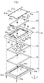
- a cell phone 10 includes a battery lid 11, a battery pack 12, a cell-phone lower case 13, a board 14, a touch panel 15 equipped with an LCD (Liquid Crystal Display), and a cell-phone upper case 16.
- the cell phone 10 has a rectangular flat shape
- each of the battery lid 11, the battery pack 12, the board 14 and the touch panel 15 has a rectangular flat shape similar to the shape of the cell phone 10, and both of the cell-phone lower case 13 and the cell-phone upper case 16 have rectangular frame shapes.
- the cell-phone lower case 13 and the cell-phone upper case 16 of the cell phone 10 form a box-shaped casing, and the structure excluding the battery pack 12 forms a cell-phone body.
- the touch panel 15 includes the LCD, and an electronic touch sensor panel covering the LCD.
- the touch sensor panel detects a position where a capacitance is changed by a touch pen or a user's finger touching the position.
- the LCD displays an arbitrary image such as an icon for allowing the user to touch the touch panel 15 to input an operation instruction.
- the touch panel 15 accepts an input made by touching of the touch pen or the like thereon.
- various functions assigned to this icon are achieved by a CPU (Central Processing Unit) 24 and a transmitter/receiver (not shown) and the like mounted on the board 14 of the cell phone 10.
- CPU Central Processing Unit
- transmitter/receiver not shown
- the touch panel 15 is accommodated in the cell-phone upper case 16 with its touch sensor panel exposed on the surface.
- the touch panel 15 is accommodated, together with the board 14, in the housing space of the casing, formed by securing the cell-phone upper case 16 to the cell-phone lower case 13 with four bolts 16a, in such a state as to overlap the board 14.
- a battery pack housing 33 having a rectangular opening 33a which penetrates the cell-phone lower case 13 in a thicknesswise direction is provided in the center portion of the cell-phone lower case 13 to house the battery pack 12.
- the battery pack 12 is housed in the battery pack housing 33 through the rectangular opening 33a of the battery pack housing 33 with the bottom side of the battery pack 12 being in contact with the bottom cover (not shown) of the board 14. Because the battery pack 12 is housed in the battery pack housing 33 in such a state, members that are present in the thicknesswise direction of the cell phone 10 are limited to the necessary components such as the battery pack 12, the board 14 and the touch panel 15, thereby contributing to flattening the cell phone 10.
- a lock mechanism (not shown) that locks the battery lid 11 on a -Y side (front side) when being slid leftward/rightward, and an operation lever 41 for setting the lock mechanism in a locked state and a free state are provided on the cell-phone lower case 13 on the -Y side (front side) of a battery lid holder 43.
- the operation lever 41 moves leftward/rightward (to the free side/lock side) in a cutaway 41a provided on the -Y side (front side) of the battery lid 11.
- the lock mechanism is configured to be mechanically locked when the operation lever 41 is manually moved to the lock side (-X side), and be unlocked when the operation lever 41 is manually moved to the free side (+X side).
- the battery lid holder 43 recessed in a rectangular frame shape from the top surface of the cell-phone lower case 13 is formed in the peripheral region of the rectangular opening of the battery pack housing 33 to hold the battery lid 11.
- a connection terminal 22 is provided on the -Y-side (front side) side face of the battery pack 12 to be connected to an unillustrated connection terminal provided on the cell phone body (cell-phone lower case 13).
- the cell phone 10 further includes a battery lock member 50 for fixing the +Y side (rear side) of the battery pack 12 to lock the battery pack 12 in a fixed position in the battery pack housing 33.
- An elongated pressing portion (not shown) for locking the front peripheral portion of the battery pack 12 from above is protrusively formed on the -Y side (front side) of the battery pack housing 33 in such a way as to extend a leftward/rightward direction.
- the front peripheral portion of the battery pack 12 is slipped into the space under the pressing portion.
- This structure and the battery lock member 50 cause the battery pack 12 to be locked at the front and rear portions thereof, so that the battery pack 12 is stably housed in the battery pack housing 33.
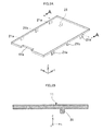
- two inward engagement claws 21a are protrusively formed at a predetermined interval therebetween in the vicinity of each of both ⁇ X direction (leftward/rightward) sides of the battery lid 11 in a -Z direction (downward), and a single inward engagement claw 2 1 b is protrusively formed between the two outward engagement claws 21a in the -Z direction (downward).
- the outward engagement claw 21a has an engagement protrusion protruding outward
- the inward engagement claw 21b has an engagement protrusion protruding inward.
- FIG. 1 As shown in FIG. 1 , four engagement portions 23a with which the four outward engagement claws 21 of the battery lid 11 are engaged, and two engagement holes 23b with which the two inward engagement claws 21b of the battery lid 11 are engaged are formed at corresponding positions of the battery lid holder 43.
- the battery lid 11 When the battery lid 11 is attached to the battery lid holder 43, the battery lid 11 is held on the battery lid holder 43 and closes the opening of the battery pack housing 33 with the outward engagement claws 21a and the inward engagement claws 21b of the battery lid 11 being respectively engaged with the engagement portions 23a and the engagement holes 23b of the battery lid holder 43.
- This engagement structure permits the battery lid 11 to be stably held on the battery lid holder 43.
- the bottom surface of the battery lid 11 substantially contacts the top surface of the battery pack 12 (see FIG. 8 ).
- a depression protrusion 31 with a quadratic prism shape is protrusively formed in the -Z direction (downward) on the bottom side of the battery lid 11 in a predetermined position.
- the depression protrusion 31 of the battery lid 11 is disposed in a position where the depression protrusion 31 abuts on a second inclined surface 56 or a left side face 57 of a lock portion 52 of the battery lock member 50 to be described later with the battery lid 11 being held on the battery lid holder 43(see FIGS. 4 and 8 ).
- an engagement protrusion 32 with a trapezoidal cross section is protrusively formed at a center portion of the +Y-side (front side) side face of the battery pack 12.
- the engagement protrusion 32 has a front face 32a parallel to the frontward side face of the battery pack 12, a bottom face 32b flush with the bottom face of the battery pack 12, a back face 32c inclined with respect to the bottom face 32b so that the +X side (left side) becomes lower, and a pair of a first side face 32d and a second side face 32e connected to the front face 32a, the bottom face 32b and the back face 32c and opposing each other horizontally.
- the first side face 32d is lower than the second side face 32e.
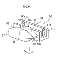
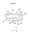
- the battery lock member 50 includes a substantially rectangular cylindrical slide 51 having a guided groove 51a extending in the ⁇ X direction (leftward/rightward) and opening to the +Z side (upper side) like a slit, and the lock portion 52 formed integral with the slide 51 and protruding from the -Y-side (front side) side face of the slide 51.
- a pair of projections 51 b extending in the Z direction (upward/downward) and projecting inward are formed near the left and right end portions of the +Y-side side face of the guided groove 51a.
- a pressing protrusion 51c protruding inward is formed on an upper central portion of the -Y-side side face of the slit opening of the guided groove 51 a.
- a pair of elongated slide assisting ribs 51d extending in the X direction are formed on the bottom face of the battery lock member 50 to protrude downward therefrom.
- the slide assisting ribs 51d are provided to reduce the slide friction by changing slide region of the battery lock member 50 from a planar region to a linear region when it sides on the surface of the bottom cover of the board 14.
- an engagement recess 53 recessed in a trapezoidal cross section is formed in a right side portion of the lock portion 52 in such a way that when the battery pack 12 is housed in the battery pack housing 33 and locked, the engagement protrusion 32 of the battery pack 12 engages with the engagement recess 53.
- first inclined surface 54 inclined so that the -X side (right side) becomes lower
- an upper surface 55 continual to the first inclined surface 54 and substantially parallel to the top face of the slide 51
- the second inclined surface 56 continual to the upper surface 55 and inclined so that the +X side (left side) becomes lower.
- the top face of the engagement recess 53 of the lock portion 52 serves as a third inclined surface 53a that faces the back face 32c of the engagement protrusion 32 (see FIG. 3B ) in parallel thereto when the engagement recess 53 engages with the engagement protrusion 32 of the battery pack 12.
- the left side face 57 is formed at the lock portion 52 to be continual to the second inclined surface 56.
- first inclined surface 54 and the second inclined surface 56 of the battery lock member 50 face each other so as to form a first angular portion therebetween along the moving direction ( ⁇ X direction) of the battery lock member 50 (see FIG. 5 ), and the first inclined surface 54 and the third inclined surface 53a of the battery lock member 50 face each other so as to form a second angular portion therebetween along the moving direction of the battery lock member 50.
- the above structure permits the lock portion 52 of the battery lock member 50 to be formed compact.
- a recessed space 70 is formed in the -Y side (rear side) of the battery lid holder 43.
- the battery lock member 50 is configured to be accommodated in the recessed space 70 and slide in the ⁇ X direction along a guide rail 13b provided in the recessed space 70.
- the guide rail 13b is formed to protrude downward from a part 13a of the cell-phone lower case 13. Accordingly, the battery lock member 50 is reasonably accommodated in the cell phone body while saving the layout space for the battery lock member 50. Specifically, referring to FIG.
- the battery lock member 50 is configured in such a way that the guided groove 51a of the slide 51 is slidably fitted over the guide rail 13b and that a projection 13c formed at the lower portion of the guide rail 13b so as to extend in the leftward/rightward direction and protrude toward the -Y side is hooked on the pressing protrusion 51c of the guided groove 51 a, thereby preventing the battery lock member 50 from coming off the guide rail 13b.
- contact of the pair of projections 51b of the guided groove 51a with the guide rail 13b in a linear region reduces the slide friction between the guide rail 13b and the guided groove 51a.
- the slide 51 of the battery lock member 50 is formed of a hard resin such as polyacetal, and the aforementioned structure prevents the battery lock member 50 from coming off the guide rail 13b. Further, this structure suppresses the force of causing the battery pack 11 at the time of drop impact of the cell phone 10.
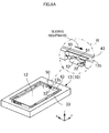
- the cell phone 10 is configured as described above, and the following describes an operation of housing the battery pack 12 in the battery pack housing 33 of the cell phone body (cell-phone lower case 13) and sealing the battery pack 12 therein with the battery lid 11.
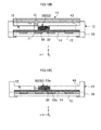
- the downward movement of the engagement protrusion 32 presses the battery lock member 50 (lock portion 52) in the +X side direction (leftward), so that the battery lock member 50 slides toward the side of unlocking the battery pack 12 (toward a left side face 71 of the recessed space 70) as shown in FIG. 9B .
- the battery lock member 50 slides on the surface of the bottom cover of the board 14 via the pair of slide assisting ribs 51d.
- the battery pack 12 is housed in the battery pack housing 33.
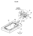
- the engagement recess 53 of the lock portion 52 engages with the engagement protrusion 32 of the battery pack 12, causing the battery pack 12 to be locked in the battery pack housing 33 with the battery lock member 50 (see FIG. 6A ).
- the third inclined surface 53a of the engagement recess 53 of the lock portion 52 and the back face 32c of the engagement protrusion 32 of the battery pack 12 faces each other in parallel.
- the depression protrusion 31 of the battery lid 11 is accommodated in the space formed between the left side face 57 of the lock portion 52 of the battery lock member 50 and the left side face 71 of the recessed space 70.
- the depression protrusion 31 of the battery lid 11 abuts on the left side face 57 of the lock portion 52 of the battery lock member 50, so that the locked state becomes stable.
- the battery lid 11 is held on the battery lid holder 43 with the outward engagement claws 21a and the inward engagement claws 21 b of the battery lid 11 (see FIG. 2A ) being engaged with the engagement portions 23a and the engagement holes 23b of the battery lid holder 43.
- the operation lever 41 is manipulated to the lock side to lock the battery lid 11 to the cell-phone lower case 13.
- the following describes an operation of detaching the battery lid 11 from the cell-phone lower case 13 (battery lid holder 43) of the cell phone 10 according to the embodiment, and further removing the battery pack 12 from the battery pack housing 33.
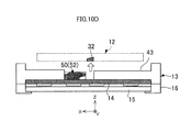
- the battery lid 11 With the battery lid 11 held on the battery lid holder 43 and the battery pack 12 sealed inside the battery pack housing 33 as shown in FIG. 10A , the battery lid 11 is detached from the battery lid holder 43 while manipulating the operation lever 41 to the free side to disengage the outward engagement claws 21a and the inward engagement claws 21b of the battery lid 11 from the engagement portions 23a and the engagement holes 23b of the battery lid holder 43.
- the depression protrusion 31 of the battery lid 11 is separated from the space formed between the left side face 57 of the lock portion 52 of the battery lock member 50 and the left side face 71 of the recessed space 70.
- the battery lock member 50 is released from the restriction by the depression protrusion 31 of the battery lid 11, so that the battery lock member 50 is freely slidable along the guide rail 13b (see FIG. 5 ).
- the third inclined surface 53a of the engagement recess 53 of the lock portion 52 and the back face 32c of the engagement protrusion 32 of the battery pack 12 faces each other in parallel.
- the operation of housing the battery pack 12 into the battery pack housing 33 causes the bottom face 32b of the engagement protrusion 32 of the battery pack 12 to slide in contact with the first inclined surface 54 of the lock portion 52 of the battery lock member 50 located in the position of locking the battery pack 12. Then, the downward movement of the engagement protrusion 32 presses the battery lock member 50 leftward, so that the battery lock member 50 slides in the direction of unlocking the battery pack 12. Then, the locking of the battery pack 12 is released.
- the operation of attaching the battery lid 11 to the battery lid holder 43 causes the depression protrusion 31 of the battery lid 11 to slide in contact with the second inclined surface 56 of the lock portion 52 of the battery lock member 50 located in the position of unlocking the battery pack 12. Then, the downward movement of the depression protrusion 31 presses the battery lock member 50 rightward, so that the battery lock member 50 slides in the direction of locking the battery pack 12. Then, the battery pack 12 is locked.
- the battery lock member 50 when the battery pack 12 housed in the battery pack housing 33 is pulled upward with the battery lock member 50 being in the locked state, the back face 32c of the engagement protrusion 32 of the battery pack 12 slides in contact with the third inclined surface 53a of the engagement recess 53 of the lock portion 52. Then, the battery lock member 50 moves toward the +X side (left side). This automatically releases the locking of the battery pack 12 in the battery pack housing 33 with the battery lock member 50. As a result, removable of the battery pack 12 from the cell phone 10 is carried out easily.
- the depression protrusion 31 of the battery lid 11 abuts on the left side face 57 of the lock portion 52 of the battery lock member 50. This stabilizes the locked state of the battery pack 12 with the battery lock member 50. As a result, electrical connection of the connection terminal 22 provided on the battery pack 12 to the connection terminal (not shown) provided on the cell-phone lower case 13 is maintained in a stable state.
- the battery lock member 50 is automatically set in the unlocked state, thus preventing the battery pack 12 and the cell phone body from being damaged.
- the battery lock member 50 is automatically set in the unlocked state, thus preventing the battery pack 12 and the cell phone body from being damaged.
- the invention is not limited to a cell phone illustrated in the foregoing description of the embodiment, and may be adapted to portable communication terminals such as a PDA (Personal Digital Assistant), a PHS (Personal Handy-phone System), a mobile PC (Personal Computer) and a tablet terminal, and other electronic apparatuses.
- portable communication terminals such as a PDA (Personal Digital Assistant), a PHS (Personal Handy-phone System), a mobile PC (Personal Computer) and a tablet terminal, and other electronic apparatuses.
- the battery lock member 50 is provided only on one side of the battery pack 12 in the lengthwise direction. That is, the recessed space 70 is provided in the -Y side (rear side) region of the battery lid holder 43, the battery lock member 50 is accommodated in the recessed space 70, and the battery lock member 50 sides in the ⁇ X direction along the guide rail 13b formed in the recessed space 70.
- the battery lock member 50 is not limited to this type, and may be provided on both lengthwise sides of the battery pack 12.
- the recessed space 70 may be formed in each of the ⁇ Y side (front and rear) regions of the battery lid holder 43, and a single battery lock member 50 is accommodated in each recessed space 70, and may slide in ⁇ X direction along the guide rail 13b formed in each recessed space 70.
- the provision of the battery lock member 50 on both lengthwise sides of the battery pack 12 this way further stabilizes the locked state of the battery pack 12 in the battery pack housing 33.
- electrical connection of the connection terminal 22 provided on the battery pack 12 to the connection terminal (not shown) provided on the cell-phone lower case 13 is maintained in a more stable state.
- the cell phone 10 includes the touch panel 15 that serves both the LCD equipped display and the key operator.
- the cell phone 10 is not limited to this type, and may be configured to have the LCD equipped display and the key operator separately.
- the guide portion to slide the battery lock member 50 is the rail-like guide rail 13b, and the guided portion is the recessed guided groove 51a that is slidably fitted on the guide rail 13b.
- the guide portion for sliding the battery lock member 50 may be a recessed guide groove
- the guided portion may be a rail-like guided rail that is slidably fitted into the guide groove.
- the first portion of the battery pack 12 is the engagement protrusion 32 with a trapezoidal cross section, which is formed to protrude from the center portion of the +Y-side (front side) side face of the battery pack 12, and is used for locking the battery pack 12.
- the first portion of the battery pack 12 may be formed to protrude from another portion such as the bottom face of the battery pack 12, or may not be used to lock the battery pack 12, as long as the effects of the invention are demonstrated.
- the first portion of the battery pack 12 may have a shape other than the trapezoidal cross-sectional shape.
- the second portion of the battery lid 11 is the depression protrusion 31 with a quadratic prism shape formed to protrude from the bottom face of the battery lid 11.
- the second portion of the battery lid 11 is not limited to this type, and may be formed to protrude from another portion such as a side portion of the battery lid 11, or may have a shape other than the quadratic prism shape, as long as the effects of the invention are demonstrated.
- the cell phone 10 and its components have rectangular shapes, which are not restrictive, and may be elliptical shapes or may have structures with curved surfaces from the viewpoint of design.
- the joint portion of the battery lid 11 and the battery lid holder 43 may be made liquid tight by a rubber packing.
- a battery pack lock structure comprising:
- the battery pack lock structure according to Note 1 or 2, wherein the battery lock member locks the battery pack with the first portion of the battery pack.
- the battery pack lock structure according to any one of Notes 1 to 4, wherein a guide portion that permits slide movement of the battery lock member is provided in the electronic apparatus body.
- the battery pack lock structure according to Note 5 or 6, wherein a battery lid holder for holding the battery lid is provided at a peripheral region of the opening of the battery pack housing, and the guide portion is provided in a recessed space formed in the battery lid holder.
- the battery pack lock structure according to Note 5 wherein the battery lock member is provided with a guided portion that is slidably fitted on the guide portion.
Landscapes
- Engineering & Computer Science (AREA)
- Signal Processing (AREA)
- Battery Mounting, Suspending (AREA)
Applications Claiming Priority (2)
| Application Number | Priority Date | Filing Date | Title |
|---|---|---|---|
| JP2010243525 | 2010-10-29 | ||
| PCT/JP2011/074733 WO2012057238A1 (ja) | 2010-10-29 | 2011-10-26 | 電池パックのロック構造及び電子機器 |
Publications (2)
| Publication Number | Publication Date |
|---|---|
| EP2634833A1 true EP2634833A1 (de) | 2013-09-04 |
| EP2634833A4 EP2634833A4 (de) | 2017-01-04 |
Family
ID=45993943
Family Applications (1)
| Application Number | Title | Priority Date | Filing Date |
|---|---|---|---|
| EP11836371.2A Withdrawn EP2634833A4 (de) | 2010-10-29 | 2011-10-26 | Batteriepack-verriegelungsanordnung und elektronische vorrichtung |
Country Status (5)
| Country | Link |
|---|---|
| US (1) | US9735400B2 (de) |
| EP (1) | EP2634833A4 (de) |
| JP (1) | JP5861643B2 (de) |
| CN (1) | CN103201874B (de) |
| WO (1) | WO2012057238A1 (de) |
Families Citing this family (21)
| Publication number | Priority date | Publication date | Assignee | Title |
|---|---|---|---|---|
| WO2013047421A1 (ja) * | 2011-09-26 | 2013-04-04 | Necカシオモバイルコミュニケーションズ株式会社 | 電子機器 |
| JP2014102913A (ja) * | 2012-11-16 | 2014-06-05 | Nintendo Co Ltd | 電池を用いる手持ち型電子装置および電池ユニット |
| JP6032482B2 (ja) * | 2012-12-26 | 2016-11-30 | パナソニックIpマネジメント株式会社 | 電子機器 |
| US9269935B2 (en) * | 2013-01-29 | 2016-02-23 | Varian Medical Systems, Inc. | Battery pack with integral seal member and electronic device including the same |
| WO2015097939A1 (ja) * | 2013-12-25 | 2015-07-02 | パナソニックIpマネジメント株式会社 | 電子機器の筐体、電子機器 |
| JP6335691B2 (ja) | 2014-03-03 | 2018-05-30 | キヤノン株式会社 | 電子機器 |
| US9904320B2 (en) * | 2014-05-30 | 2018-02-27 | Microsoft Technology Licensing, Llc | Battery compartments for wearable electronic device |
| JP6025228B1 (ja) * | 2015-05-15 | 2016-11-16 | Necプラットフォームズ株式会社 | ディスプレイ装置 |
| JP6152404B2 (ja) * | 2015-07-28 | 2017-06-21 | 京セラ株式会社 | 電子機器 |
| JP6361623B2 (ja) * | 2015-10-05 | 2018-07-25 | 株式会社デンソー | 固定装置 |
| JP6080235B1 (ja) * | 2015-12-01 | 2017-02-15 | Necプラットフォームズ株式会社 | 電池パックの収容構造、および電子機器 |
| JP6116039B1 (ja) * | 2017-01-11 | 2017-04-19 | Necプラットフォームズ株式会社 | 電池パックの収容構造、および電子機器 |
| JP6734803B2 (ja) * | 2017-03-23 | 2020-08-05 | 京セラ株式会社 | 電子機器 |
| KR102675963B1 (ko) * | 2018-07-11 | 2024-06-14 | 삼성에스디아이 주식회사 | 이차전지 및 전지모듈 |
| EP3648558A1 (de) | 2018-11-05 | 2020-05-06 | Koninklijke Philips N.V. | Gehäuse mit interner verriegelungsanordnung |
| USD912487S1 (en) | 2019-06-12 | 2021-03-09 | Techtronic Cordless Gp | Interface of a power tool |
| US11145929B2 (en) | 2019-08-09 | 2021-10-12 | Techtronic Cordless Gp | Battery pack |
| US11382221B2 (en) * | 2019-11-19 | 2022-07-05 | Ricoh Company, Ltd. | Information display device |
| US11848454B2 (en) * | 2020-04-09 | 2023-12-19 | Apple Inc. | Battery enclosures with structural enhancements |
| EP4254622A4 (de) * | 2021-10-15 | 2024-03-06 | Contemporary Amperex Technology Co., Limited | Batterie, elektrische vorrichtung sowie verfahren und vorrichtung zur herstellung der batterie |
| US20260016857A1 (en) * | 2024-07-11 | 2026-01-15 | Remarkable As | Locking mechanism for thin bezel and repairable device |
Family Cites Families (8)
| Publication number | Priority date | Publication date | Assignee | Title |
|---|---|---|---|---|
| JP3060291B2 (ja) | 1996-10-09 | 2000-07-10 | 松下電器産業株式会社 | 電池パックの保持装置 |
| JPH1154099A (ja) | 1997-08-08 | 1999-02-26 | Saitama Nippon Denki Kk | 電池パックの着装構造及び携帯型電子端末 |
| JP2001176475A (ja) | 1999-12-17 | 2001-06-29 | Hitachi Kokusai Electric Inc | 携帯電話機のバッテリ保持構造 |
| EP3300181A1 (de) | 2001-07-25 | 2018-03-28 | Sony Corporation | Strukturen von endgeräten und zu ladende komponente |
| KR100531852B1 (ko) | 2003-03-25 | 2005-11-30 | 엘지전자 주식회사 | 배터리 커버 로킹장치 |
| JP2009032595A (ja) | 2007-07-27 | 2009-02-12 | Nec Saitama Ltd | 携帯型電子機器ケースの電池パック収納部構造 |
| CN101540384B (zh) * | 2008-03-18 | 2013-04-24 | 深圳富泰宏精密工业有限公司 | 电池盖及具有该电池盖的电子装置 |
| CN101887952B (zh) * | 2009-05-15 | 2013-01-09 | 深圳富泰宏精密工业有限公司 | 电池盖卡锁结构及该便携式电子装置 |
-
2011
- 2011-10-26 CN CN201180051629.3A patent/CN103201874B/zh not_active Expired - Fee Related
- 2011-10-26 EP EP11836371.2A patent/EP2634833A4/de not_active Withdrawn
- 2011-10-26 US US13/881,988 patent/US9735400B2/en not_active Expired - Fee Related
- 2011-10-26 JP JP2012540921A patent/JP5861643B2/ja not_active Expired - Fee Related
- 2011-10-26 WO PCT/JP2011/074733 patent/WO2012057238A1/ja not_active Ceased
Non-Patent Citations (1)
| Title |
|---|
| See references of WO2012057238A1 * |
Also Published As
| Publication number | Publication date |
|---|---|
| EP2634833A4 (de) | 2017-01-04 |
| US20130209866A1 (en) | 2013-08-15 |
| CN103201874A (zh) | 2013-07-10 |
| JP5861643B2 (ja) | 2016-02-16 |
| US9735400B2 (en) | 2017-08-15 |
| JPWO2012057238A1 (ja) | 2014-05-12 |
| CN103201874B (zh) | 2016-02-17 |
| WO2012057238A1 (ja) | 2012-05-03 |
Similar Documents
| Publication | Publication Date | Title |
|---|---|---|
| US9735400B2 (en) | Battery pack lock structure and electronic apparatus | |
| CN103228115B (zh) | 电子设备 | |
| US8248812B2 (en) | Cover latching assembly for electronic device | |
| JP2012033489A (ja) | 電池蓋ロック機構及びそれを用いた電子装置 | |
| US9052872B2 (en) | Electronic device | |
| US20080100262A1 (en) | Mobile terminal device | |
| EP1858233B1 (de) | Verschlussanordnung für eine Batterieeinheit eines Mobiltelefons, und Mobiltelefon | |
| JP5181844B2 (ja) | キーボード、電子機器、キーボードの製造方法、電子機器の製造方法及びキーボード部品 | |
| CN101233796B (zh) | 电子设备以及该电子设备用的框体 | |
| US8257852B2 (en) | Battery cover mechanism | |
| US8165650B2 (en) | Portable electronic device | |
| JP2013153095A (ja) | 電池収納部の防滴構造および電子機器 | |
| TW201022897A (en) | Battery cover lock structure | |
| CN111031728A (zh) | 电子设备、装配方法及拆卸方法 | |
| JP2014086980A (ja) | 携帯電子機器 | |
| TWI407020B (zh) | 電池蓋鎖持機構 | |
| JP4752277B2 (ja) | 電子機器における電池のロック構造 | |
| JP4697064B2 (ja) | 折り畳み式の電子機器 | |
| JP6048708B1 (ja) | 電子機器 | |
| TWI418283B (zh) | 滑蓋式電子裝置 | |
| JP2009246454A (ja) | 接続機器 | |
| JPH10333774A (ja) | 電子機器 | |
| JP4920917B2 (ja) | 携帯型電子機器 | |
| TWI431457B (zh) | 電池蓋卡鎖結構 | |
| JP2017118195A (ja) | 電子機器 |
Legal Events
| Date | Code | Title | Description |
|---|---|---|---|
| PUAI | Public reference made under article 153(3) epc to a published international application that has entered the european phase |
Free format text: ORIGINAL CODE: 0009012 |
|
| 17P | Request for examination filed |
Effective date: 20130522 |
|
| AK | Designated contracting states |
Kind code of ref document: A1 Designated state(s): AL AT BE BG CH CY CZ DE DK EE ES FI FR GB GR HR HU IE IS IT LI LT LU LV MC MK MT NL NO PL PT RO RS SE SI SK SM TR |
|
| DAX | Request for extension of the european patent (deleted) | ||
| RAP1 | Party data changed (applicant data changed or rights of an application transferred) |
Owner name: NEC CORPORATION |
|
| RA4 | Supplementary search report drawn up and despatched (corrected) |
Effective date: 20161205 |
|
| RIC1 | Information provided on ipc code assigned before grant |
Ipc: H04M 1/02 20060101ALI20161129BHEP Ipc: H01M 2/10 20060101AFI20161129BHEP |
|
| STAA | Information on the status of an ep patent application or granted ep patent |
Free format text: STATUS: THE APPLICATION HAS BEEN WITHDRAWN |
|
| 18W | Application withdrawn |
Effective date: 20171114 |