EP2634891A2 - Drahtloses Ladesteuerungsverfahren und drahtlose Ladevorrichtung damit - Google Patents
Drahtloses Ladesteuerungsverfahren und drahtlose Ladevorrichtung damit Download PDFInfo
- Publication number
- EP2634891A2 EP2634891A2 EP13156888.3A EP13156888A EP2634891A2 EP 2634891 A2 EP2634891 A2 EP 2634891A2 EP 13156888 A EP13156888 A EP 13156888A EP 2634891 A2 EP2634891 A2 EP 2634891A2
- Authority
- EP
- European Patent Office
- Prior art keywords
- wireless power
- charging
- resonator
- transmission
- power receiving
- Prior art date
- Legal status (The legal status is an assumption and is not a legal conclusion. Google has not performed a legal analysis and makes no representation as to the accuracy of the status listed.)
- Withdrawn
Links
Images


Classifications
-
- H—ELECTRICITY
- H02—GENERATION; CONVERSION OR DISTRIBUTION OF ELECTRIC POWER
- H02J—ELECTRIC POWER NETWORKS; CIRCUIT ARRANGEMENTS OR SYSTEMS FOR SUPPLYING OR DISTRIBUTING ELECTRIC POWER; SYSTEMS FOR STORING ELECTRIC ENERGY
- H02J50/00—Circuit arrangements or systems for wireless supply or distribution of electric power
- H02J50/80—Circuit arrangements or systems for wireless supply or distribution of electric power involving the exchange of data, concerning supply or distribution of electric power, between transmitting devices and receiving devices
-
- H—ELECTRICITY
- H02—GENERATION; CONVERSION OR DISTRIBUTION OF ELECTRIC POWER
- H02J—ELECTRIC POWER NETWORKS; CIRCUIT ARRANGEMENTS OR SYSTEMS FOR SUPPLYING OR DISTRIBUTING ELECTRIC POWER; SYSTEMS FOR STORING ELECTRIC ENERGY
- H02J50/00—Circuit arrangements or systems for wireless supply or distribution of electric power
- H02J50/10—Circuit arrangements or systems for wireless supply or distribution of electric power using inductive coupling
- H02J50/12—Circuit arrangements or systems for wireless supply or distribution of electric power using inductive coupling of the resonant type
-
- H—ELECTRICITY
- H02—GENERATION; CONVERSION OR DISTRIBUTION OF ELECTRIC POWER
- H02J—ELECTRIC POWER NETWORKS; CIRCUIT ARRANGEMENTS OR SYSTEMS FOR SUPPLYING OR DISTRIBUTING ELECTRIC POWER; SYSTEMS FOR STORING ELECTRIC ENERGY
- H02J50/00—Circuit arrangements or systems for wireless supply or distribution of electric power
- H02J50/40—Circuit arrangements or systems for wireless supply or distribution of electric power using two or more transmitting or receiving devices
-
- H—ELECTRICITY
- H02—GENERATION; CONVERSION OR DISTRIBUTION OF ELECTRIC POWER
- H02J—ELECTRIC POWER NETWORKS; CIRCUIT ARRANGEMENTS OR SYSTEMS FOR SUPPLYING OR DISTRIBUTING ELECTRIC POWER; SYSTEMS FOR STORING ELECTRIC ENERGY
- H02J2105/00—Networks for supplying or distributing electric power characterised by their spatial reach or by the load
- H02J2105/40—Networks for supplying or distributing electric power characterised by their spatial reach or by the load characterised by the loads connecting to the networks or being supplied by the networks
- H02J2105/44—Portable electronic devices
-
- H—ELECTRICITY
- H02—GENERATION; CONVERSION OR DISTRIBUTION OF ELECTRIC POWER
- H02J—ELECTRIC POWER NETWORKS; CIRCUIT ARRANGEMENTS OR SYSTEMS FOR SUPPLYING OR DISTRIBUTING ELECTRIC POWER; SYSTEMS FOR STORING ELECTRIC ENERGY
- H02J7/00—Circuit arrangements for charging or discharging batteries or for supplying loads from batteries
- H02J7/90—Regulation of charging or discharging current or voltage
- H02J7/933—Regulation of charging or discharging current or voltage the cycle being controlled or terminated in response to electric parameters
Definitions
- the present invention relates generally to a charging control method and apparatus, and more particularly, to a method and apparatus for controlling a supply of wireless charging power.
- a resonance type wireless power transmission scheme which is able to charge a device at a relatively long distance (in contrast a typical wireless charging scheme using inductive coupling at a short distance) has been recently proposed, and research for the resonance type wireless power transmission scheme is currently ongoing.
- the resonance type wireless power transmission scheme is based on Evanescent Wave Coupling wherein, when two mediums resonate with each other at the same frequency, electromagnetic waves move from one medium to the other medium through a short-distance electromagnetic field.
- a charging station connected to a power source generates an electromagnetic field
- a wireless power receiving apparatus designed with the same resonance frequency in a megahertz (MHz) band approaches the charging station within the generated electromagnetic field.
- MHz megahertz
- the energy generated in the resonance type wireless power transmission scheme is non-radiative and is based on the electromagnetic field, the energy is only transferred to an apparatus that has the same resonance frequency. Further, an unused portion of the energy is absorbed back into the electromagnetic field, instead of being spread into the air. Therefore, unlike other electromagnetic waves, the electromagnetic waves generated in the resonance type wireless power transmission scheme do not have any effect on surrounding machines or bodies.
- FIG. 1 is a block diagram illustrating a construction of a conventional resonance type wireless power transmission system
- FIG. 2 is a signal flow diagram illustrating an operation of a conventional resonance type wireless power transmission system.
- a wireless power transmitting apparatus 10 wirelessly supplies power to a plurality of wireless power receiving apparatuses 20.
- the wireless power transmitting apparatus 10 receives a request for wireless power supply from a third wireless power receiving apparatus 23, and additionally supplies the wireless power to the third wireless power receiving apparatus 23. Further, while the second and third wireless power receiving apparatuses 22 and 23 are receiving the wireless power supplied from the wireless power transmitting apparatus 10, the charging of the first wireless power receiving apparatus 21 is completed.
- the wireless power transmitting apparatus 10 wirelessly supplies power to the first and second wireless power receiving apparatus 21 and 22, in step 201. Thereafter, the third wireless power receiving apparatus 23 requests the wireless power transmitting apparatus 10 to supply wireless power, in step 202. Accordingly, the wireless power transmitting apparatus 10 calculates the charging power required by the first, second and third wireless power receiving apparatuses 21, 22, and 23, and calculates the sum of the wireless power to be transmitted to the first, second and third wireless power receiving apparatuses 21, 22, and 23, in step 203. Then, the wireless power transmitting apparatus 10 transmits the sum of the wireless power calculated in step 203 to the first, second and third wireless power receiving apparatuses 21, 22, and 23, in step 204.
- the first wireless power receiving apparatus 21 notifies the wireless power transmitting apparatus 10 of the completion of the charging, in step 205.
- the wireless power transmitting apparatus 10 calculates the charging power required by the second and third wireless power receiving apparatuses 22 and 23, and calculates the sum of the wireless power to be transmitted to the second and third wireless power receiving apparatuses 22 and 23, in step 206. Then, the wireless power transmitting apparatus 10 transmits the sum of the wireless power calculated in step 206 to the second and third wireless power receiving apparatuses 22 and 23, in step 207.
- a conventional wireless power transmission system wirelessly supplies power to a plurality of wireless power receiving apparatuses 20.
- the conventional wireless power transmission system has a problem in that the conventional system cannot individually control the wireless power provided to each of the plurality of wireless power receiving apparatuses 20.
- the wireless power transmitting apparatus 10 in wirelessly supplying power to the plurality of wireless power receiving apparatuses 20 by the wireless power transmitting apparatus 10, the wireless power transmitting apparatus 10 merely transmits the sum of the wireless power requested by the plurality of wireless power receiving apparatuses 20, regardless of any difference between powers required by the respective wireless power receiving apparatuses 20. Therefore, under some circumstances, the power transmitted by the wireless power transmitting apparatus 10 may be less than the power required for charging the wireless power receiving apparatuses 20, which may make it impossible to perform a normal charging.
- an aspect of the present invention is to address the above-mentioned problems occurring in the prior art, and provide at least the advantages described below.
- Another aspect of the present invention is to provide a method for providing wireless power to a plurality of wireless power receiving apparatuses by a single wireless power supplying apparatus.
- a method of controlling charging of a battery by a wireless power receiving apparatus, using a charging power provided from a wireless power transmission device includes initiating charging of a battery by using a charging power provided by a resonator for wirelessly receiving power; determining whether charging of the battery has been completed; and terminating, when the charging of the battery has been completed, an operation of the resonator.
- a wireless power receiving apparatus for wirelessly receiving electric power from a wireless power transmitting apparatus through an electromagnetic coupling with the wireless power transmitting apparatus.
- the wireless power receiving apparatus includes a reception resonator set to a resonance frequency equal to a resonance frequency of a wireless power transmission apparatus, the reception resonator being coupled with a transmission resonator of the wireless power transmitting apparatus and receiving electric power from the transmission resonator; a switch connected to the reception resonator; and a charging controller for supplying the electric power received through the reception resonator to a battery, determining whether charging of the battery has been completed, controlling the switch such as to cease operation of the reception resonator upon determining that charging of the batter has completed.
- a wireless power transmitting apparatus for wirelessly supplying electric power to a wireless power receiving apparatus through an electromagnetic coupling with the wireless power receiving apparatus.
- the wireless power transmitting apparatus includes a transmission resonator set to a resonance frequency equal to a resonance frequency of a wireless power receiving apparatus, the transmission resonator being coupled with a reception resonator of the wireless power receiving apparatus and providing electric power to the reception resonator; and a transmission controller for controlling an operation of the transmission resonator according to a charging state of the wireless power receiving apparatus.
- the present invention has been made to solve the above-mentioned problems and provides a method and an apparatus for controlling a wireless power receiving apparatuses by connecting an on/off switch to a reception resonator of the wireless power receiving apparatus.
- FIG. 3 is a block diagram illustrating a construction of a wireless power receiving apparatus 30 according to an embodiment of the present invention
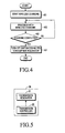
- FIG. 5 is a block diagram illustrating a construction of a wireless power transmitting apparatus 50 according to an embodiment of the present invention.
- the wireless power receiving apparatus 30 includes a reception resonator 31, a switch 32, a charging controller 33, and a battery 34.
- the reception resonator 31 is set to have the same resonance frequency as a resonance frequency of a transmission resonator 51 of the wireless power transmitting apparatus 50. Accordingly, the reception resonator 31 is coupled and resonates with the transmission resonator 51.
- the reception resonator 31 of the wireless power receiving apparatus 30 is coupled and resonates with the transmission resonator 51 of the wireless power transmitting apparatus 50, wireless power is transferred from the wireless power transmitting apparatus 50 to the wireless power receiving apparatus 30, and the wireless power receiving apparatus 30 is thus charged.
- the switch 32 is connected with the reception resonator 31, so as to control the coupling between the reception resonator 31 and the transmission resonator 51 of the wireless power transmitting apparatus 50.
- the charging controller 33 interrupts the connection between the reception resonator 31 and the battery 34 in order to terminate the connection between the reception resonator 31 and the battery 34. To this end, the charging controller 33 checks whether the charging of the battery 34 has been completed. When the charging has been completed, the charging controller 33 controls the switch 32 (i.e., opens or closes the switch 32) so as to interrupt the coupling between the reception resonator 31 and the transmission resonator 51 of the wireless power transmitting apparatus 50.
- FIG. 4 is a flowchart illustrating a charging control method according to an embodiment of the present invention.
- step 401 the wireless power receiving apparatus 30 starts wireless charging by receiving power transmitted from the wireless power transmitting apparatus 50 and supplying the charging power to the battery 34.
- step 402 the wireless power receiving apparatus 30 continues receiving wireless charging power while consistently monitoring at least one of the voltage of the battery 34 and the charging current provided to the battery 34. Based upon the monitoring, the wireless power receiving apparatus 30 checks whether the charging of the battery 34 has been completed in step 403.
- step 403 Upon a determination that charging has been completed, in step 403, the switch 32 connected to the reception resonator 31 of the wireless power receiving apparatus 30 is turned off, in step 404. As a result, the coupling between the reception resonator 31 and the transmission resonator 51 of the wireless power transmitting apparatus 50 is terminated, and the wireless power receiving apparatus 30 does not receive any more wireless power from the wireless power transmitting apparatus 50.
- the wireless power transmitting apparatus 50 consistently provides the charging power that it can provide, the wireless power receiving apparatus 30 prevents an unnecessary supply of power to the battery 34 of the wireless power receiving apparatus 30, after battery 34 is completely charged. Further, since unnecessary charging is prevented as described above, when there are a plurality of wireless power receiving apparatuses 30, the wireless power transmitting apparatus 50 can more intensively provide power to only the wireless power receiving apparatuses 30 that still require charging. Accordingly, charging power is more efficiently supplied to the plurality of wireless power receiving apparatuses 30.
- the wireless power transmitting apparatus 50 includes a transmission resonator 51 and a transmission controller 53 according to an embodiment of the present invention.
- the transmission resonator 51 is set to have a predetermined resonance frequency, for example, the same resonance frequency as that of the reception resonator 31 of the wireless power receiving apparatus 30, and transmits a wireless power through the resonance frequency.
- the transmission controller 53 controls the transmission of power to the wireless power receiving apparatus 30 by controlling the operation of the transmission resonator 51. Specifically, the transmission controller 53 monitors the wireless power transmitted through the transmission resonator 51, so as to determine whether the wireless power is transmitted to the wireless power receiving apparatus 30. When the reception resonator 31 of the wireless power receiving apparatus 30 is not coupled with the transmission resonator 51 and the wireless power is not transmitted to the wireless power receiving apparatus 30 at all, the transmission controller 53 stops the operation of the transmission resonator 51.
- the transmission controller 53 through communication with the wireless power receiving apparatus 30, the transmission controller 53 receives a charging power supply request from the wireless power receiving apparatus 30. In response to the charging power supply request, the transmission controller 53 determines whether to permit the transmission of power to the wireless power receiving apparatus 30, and, from among a plurality of wireless power receiving apparatuses 30, the transmission controller 53 selectively provides only to the wireless power to wireless power receiving apparatuses 30 for which the transmission of power is permitted.
- the transmission controller 53 controls power transmission to the wireless power receiving apparatus 30 by monitoring the wireless power transmitted through the transmission resonator 51.
- the transmission controller 53 receives a message, indicating that the charging has been completed, from at least one of the wireless power receiving apparatuses 30 receiving electric power through the communication with the wireless power receiving apparatus 30.
- the transmission controller 53 of the wireless power transmitting apparatus 50 stops supplying power to the corresponding wireless power receiving apparatus 30.
- the transmission controller 53 stops the transmission resonator 51 from transmitting any more power.
- a wireless power transmitting apparatus can avoid unnecessarily providing electric power to the wireless power receiving apparatus having a completely charged battery.
- the wireless power transmitting apparatus can provide a necessary quantity of power to the wireless power receiving apparatus, which enables an efficient supply of charging power.
Landscapes
- Engineering & Computer Science (AREA)
- Power Engineering (AREA)
- Computer Networks & Wireless Communication (AREA)
- Charge And Discharge Circuits For Batteries Or The Like (AREA)
Applications Claiming Priority (1)
| Application Number | Priority Date | Filing Date | Title |
|---|---|---|---|
| KR1020120020957A KR20130099445A (ko) | 2012-02-29 | 2012-02-29 | 무선 충전 제어 방법 및 이를 적용한 무선 충전 장치 |
Publications (2)
| Publication Number | Publication Date |
|---|---|
| EP2634891A2 true EP2634891A2 (de) | 2013-09-04 |
| EP2634891A3 EP2634891A3 (de) | 2018-01-10 |
Family
ID=47900577
Family Applications (1)
| Application Number | Title | Priority Date | Filing Date |
|---|---|---|---|
| EP13156888.3A Withdrawn EP2634891A3 (de) | 2012-02-29 | 2013-02-27 | Drahtloses Ladesteuerungsverfahren und drahtlose Ladevorrichtung damit |
Country Status (3)
| Country | Link |
|---|---|
| US (1) | US20130221912A1 (de) |
| EP (1) | EP2634891A3 (de) |
| KR (1) | KR20130099445A (de) |
Families Citing this family (13)
| Publication number | Priority date | Publication date | Assignee | Title |
|---|---|---|---|---|
| TWI584018B (zh) | 2014-08-03 | 2017-05-21 | 帕戈技術股份有限公司 | 穿戴式照相機系統與用於將照相機系統或其他電子裝置附接至穿戴式製品之設備及方法 |
| US9635222B2 (en) | 2014-08-03 | 2017-04-25 | PogoTec, Inc. | Wearable camera systems and apparatus for aligning an eyewear camera |
| KR20170118054A (ko) | 2014-12-23 | 2017-10-24 | 포고텍, 인크. | 무선 카메라 시스템 및 방법들 |
| US10241351B2 (en) | 2015-06-10 | 2019-03-26 | PogoTec, Inc. | Eyewear with magnetic track for electronic wearable device |
| US10481417B2 (en) | 2015-06-10 | 2019-11-19 | PogoTec, Inc. | Magnetic attachment mechanism for electronic wearable device |
| CA3041583A1 (en) | 2015-10-29 | 2017-05-04 | PogoTec, Inc. | Hearing aid adapted for wireless power reception |
| US11558538B2 (en) | 2016-03-18 | 2023-01-17 | Opkix, Inc. | Portable camera system |
| EP3539285A4 (de) | 2016-11-08 | 2020-09-02 | Pogotec, Inc. | Intelligentes gehäuse für elektronische wearable-vorrichtung |
| WO2020102237A1 (en) | 2018-11-13 | 2020-05-22 | Opkix, Inc. | Wearable mounts for portable camera |
| US12588901B2 (en) | 2020-06-11 | 2026-03-31 | Kohler Co. | Health care mirror |
| US12042043B2 (en) | 2020-06-11 | 2024-07-23 | Kohler Co. | Temperature tracking mirror |
| JP7614750B2 (ja) * | 2020-06-26 | 2025-01-16 | キヤノン株式会社 | 送電装置、プログラムおよび無線電力伝送方法 |
| US20230389819A1 (en) * | 2020-10-13 | 2023-12-07 | Cochlear Limited | Skin flap thickness estimation |
Family Cites Families (5)
| Publication number | Priority date | Publication date | Assignee | Title |
|---|---|---|---|---|
| US8796999B2 (en) * | 2009-02-12 | 2014-08-05 | Qualcomm Incorporated | Wireless power transfer for low power devices |
| EP2416470B1 (de) * | 2009-03-30 | 2019-11-13 | Fujitsu Limited | Drahtloses stromversorgungssystem, drahtlose stromübertragungseinrichtung und drahtlose stromempfangseinrichtung |
| JP5434330B2 (ja) * | 2009-07-22 | 2014-03-05 | ソニー株式会社 | 電力受信装置、電力伝送システム、充電装置および電力伝送方法 |
| JP5593926B2 (ja) * | 2010-07-29 | 2014-09-24 | ソニー株式会社 | 給電システム、給電装置および電子機器 |
| KR101768588B1 (ko) * | 2011-05-19 | 2017-08-17 | 엘지전자 주식회사 | 무선 충전에 따른 음향 출력 상태의 제어 |
-
2012
- 2012-02-29 KR KR1020120020957A patent/KR20130099445A/ko not_active Withdrawn
-
2013
- 2013-02-13 US US13/766,397 patent/US20130221912A1/en not_active Abandoned
- 2013-02-27 EP EP13156888.3A patent/EP2634891A3/de not_active Withdrawn
Non-Patent Citations (1)
| Title |
|---|
| None |
Also Published As
| Publication number | Publication date |
|---|---|
| US20130221912A1 (en) | 2013-08-29 |
| EP2634891A3 (de) | 2018-01-10 |
| KR20130099445A (ko) | 2013-09-06 |
Similar Documents
| Publication | Publication Date | Title |
|---|---|---|
| EP2634891A2 (de) | Drahtloses Ladesteuerungsverfahren und drahtlose Ladevorrichtung damit | |
| US11146091B2 (en) | Wireless power transmitter, wireless power receiver, and control methods thereof | |
| US11050303B2 (en) | Wireless charging apparatus and method | |
| US10804746B2 (en) | Method and apparatus for controlling wireless charging during mode transition of a wireless power receiving device | |
| KR102853454B1 (ko) | 무선 전력 송신기 및 무선 전력 수신기와 그 동작 방법 | |
| US10790694B2 (en) | Wireless power transmitters and receivers, and method for permitting a wireless power receiver by a wireless power transmitter | |
| US11356145B2 (en) | Wireless charging apparatus and method | |
| US10090696B2 (en) | Wireless power transmitting unit, wireless power receiving unit, and control methods thereof | |
| CN103155355B (zh) | 无线充电方法和装置 | |
| US9859719B2 (en) | Method and apparatus for wireless power transfer | |
| EP3282546B1 (de) | Einheit zur drahtlosen stromübertragung, einheit zum drahtlosen stromempfang und steuerungsverfahren dafür | |
| EP2909919B1 (de) | Drahtloser stromempfänger und verfahren zur einstellung eines schlafmodus in diesem drahtlosen stromempfänger | |
| CN102792554B (zh) | 移动终端的无线充电方法及相应的移动终端 | |
| US20180205257A1 (en) | Wireless power transmitter and vehicle control unit connected thereto | |
| CN103548238B (zh) | 用于与功率接收器通信的功率发送方法和功率发送器 | |
| US20120313447A1 (en) | Method of performing bidirectional communication between transmitter and receiver in wireless power transmission/reception system, the transmitter, and the receiver | |
| KR20130090703A (ko) | 무선 전력 충전 방법 및 장치 | |
| JP2015119559A (ja) | 電子機器、方法及びプログラム | |
| JP2016178721A (ja) | 送電装置、送電装置の制御方法、プログラム | |
| US20210013745A1 (en) | Wireless power transmitter, wireless power receiver, and control methods thereof | |
| KR101399958B1 (ko) | 대기전력 차단기능을 갖는 무접점 충전시스템 및 그 제어 방법 | |
| KR102000958B1 (ko) | 무선 충전 장치 및 방법 | |
| KR20170130166A (ko) | 무선 전력 전송 방식 스위칭 방법 및 장치 |
Legal Events
| Date | Code | Title | Description |
|---|---|---|---|
| PUAI | Public reference made under article 153(3) epc to a published international application that has entered the european phase |
Free format text: ORIGINAL CODE: 0009012 |
|
| AK | Designated contracting states |
Kind code of ref document: A2 Designated state(s): AL AT BE BG CH CY CZ DE DK EE ES FI FR GB GR HR HU IE IS IT LI LT LU LV MC MK MT NL NO PL PT RO RS SE SI SK SM TR |
|
| AX | Request for extension of the european patent |
Extension state: BA ME |
|
| PUAL | Search report despatched |
Free format text: ORIGINAL CODE: 0009013 |
|
| STAA | Information on the status of an ep patent application or granted ep patent |
Free format text: STATUS: THE APPLICATION HAS BEEN WITHDRAWN |
|
| AK | Designated contracting states |
Kind code of ref document: A3 Designated state(s): AL AT BE BG CH CY CZ DE DK EE ES FI FR GB GR HR HU IE IS IT LI LT LU LV MC MK MT NL NO PL PT RO RS SE SI SK SM TR |
|
| AX | Request for extension of the european patent |
Extension state: BA ME |
|
| RIC1 | Information provided on ipc code assigned before grant |
Ipc: H02J 7/02 20160101AFI20171201BHEP |
|
| 18W | Application withdrawn |
Effective date: 20171221 |