EP2634892A2 - Récepteur de puissance sans fil et son procédé de commande - Google Patents
Récepteur de puissance sans fil et son procédé de commande Download PDFInfo
- Publication number
- EP2634892A2 EP2634892A2 EP13157128.3A EP13157128A EP2634892A2 EP 2634892 A2 EP2634892 A2 EP 2634892A2 EP 13157128 A EP13157128 A EP 13157128A EP 2634892 A2 EP2634892 A2 EP 2634892A2
- Authority
- EP
- European Patent Office
- Prior art keywords
- wireless power
- voltage
- charging unit
- unit
- allowable voltage
- Prior art date
- Legal status (The legal status is an assumption and is not a legal conclusion. Google has not performed a legal analysis and makes no representation as to the accuracy of the status listed.)
- Granted
Links
Images



Classifications
-
- H—ELECTRICITY
- H02—GENERATION; CONVERSION OR DISTRIBUTION OF ELECTRIC POWER
- H02J—ELECTRIC POWER NETWORKS; CIRCUIT ARRANGEMENTS OR SYSTEMS FOR SUPPLYING OR DISTRIBUTING ELECTRIC POWER; SYSTEMS FOR STORING ELECTRIC ENERGY
- H02J50/00—Circuit arrangements or systems for wireless supply or distribution of electric power
- H02J50/80—Circuit arrangements or systems for wireless supply or distribution of electric power involving the exchange of data, concerning supply or distribution of electric power, between transmitting devices and receiving devices
-
- H—ELECTRICITY
- H02—GENERATION; CONVERSION OR DISTRIBUTION OF ELECTRIC POWER
- H02J—ELECTRIC POWER NETWORKS; CIRCUIT ARRANGEMENTS OR SYSTEMS FOR SUPPLYING OR DISTRIBUTING ELECTRIC POWER; SYSTEMS FOR STORING ELECTRIC ENERGY
- H02J50/00—Circuit arrangements or systems for wireless supply or distribution of electric power
- H02J50/005—Mechanical details of housing or structure aiming to accommodate the power transfer means, e.g. mechanical integration of coils, antennas or transducers into emitting or receiving devices
-
- H—ELECTRICITY
- H02—GENERATION; CONVERSION OR DISTRIBUTION OF ELECTRIC POWER
- H02J—ELECTRIC POWER NETWORKS; CIRCUIT ARRANGEMENTS OR SYSTEMS FOR SUPPLYING OR DISTRIBUTING ELECTRIC POWER; SYSTEMS FOR STORING ELECTRIC ENERGY
- H02J50/00—Circuit arrangements or systems for wireless supply or distribution of electric power
- H02J50/10—Circuit arrangements or systems for wireless supply or distribution of electric power using inductive coupling
- H02J50/12—Circuit arrangements or systems for wireless supply or distribution of electric power using inductive coupling of the resonant type
-
- H—ELECTRICITY
- H02—GENERATION; CONVERSION OR DISTRIBUTION OF ELECTRIC POWER
- H02J—ELECTRIC POWER NETWORKS; CIRCUIT ARRANGEMENTS OR SYSTEMS FOR SUPPLYING OR DISTRIBUTING ELECTRIC POWER; SYSTEMS FOR STORING ELECTRIC ENERGY
- H02J50/00—Circuit arrangements or systems for wireless supply or distribution of electric power
- H02J50/90—Circuit arrangements or systems for wireless supply or distribution of electric power involving detection or optimisation of position, e.g. alignment
-
- H—ELECTRICITY
- H02—GENERATION; CONVERSION OR DISTRIBUTION OF ELECTRIC POWER
- H02J—ELECTRIC POWER NETWORKS; CIRCUIT ARRANGEMENTS OR SYSTEMS FOR SUPPLYING OR DISTRIBUTING ELECTRIC POWER; SYSTEMS FOR STORING ELECTRIC ENERGY
- H02J7/00—Circuit arrangements for charging or discharging batteries or for supplying loads from batteries
- H02J7/02—Circuit arrangements for charging or discharging batteries or for supplying loads from batteries for charging batteries from AC mains by converters
- H02J7/04—Regulation of charging current or voltage
-
- H—ELECTRICITY
- H02—GENERATION; CONVERSION OR DISTRIBUTION OF ELECTRIC POWER
- H02J—ELECTRIC POWER NETWORKS; CIRCUIT ARRANGEMENTS OR SYSTEMS FOR SUPPLYING OR DISTRIBUTING ELECTRIC POWER; SYSTEMS FOR STORING ELECTRIC ENERGY
- H02J7/00—Circuit arrangements for charging or discharging batteries or for supplying loads from batteries
- H02J7/40—Circuit arrangements for charging or discharging batteries or for supplying loads from batteries characterised by the exchange of charge or discharge related data
- H02J7/44—Circuit arrangements for charging or discharging batteries or for supplying loads from batteries characterised by the exchange of charge or discharge related data between battery management systems and power sources
-
- H—ELECTRICITY
- H02—GENERATION; CONVERSION OR DISTRIBUTION OF ELECTRIC POWER
- H02J—ELECTRIC POWER NETWORKS; CIRCUIT ARRANGEMENTS OR SYSTEMS FOR SUPPLYING OR DISTRIBUTING ELECTRIC POWER; SYSTEMS FOR STORING ELECTRIC ENERGY
- H02J7/00—Circuit arrangements for charging or discharging batteries or for supplying loads from batteries
- H02J7/485—Circuit arrangements for charging or discharging batteries or for supplying loads from batteries with provisions for charging different types of batteries
-
- H—ELECTRICITY
- H02—GENERATION; CONVERSION OR DISTRIBUTION OF ELECTRIC POWER
- H02J—ELECTRIC POWER NETWORKS; CIRCUIT ARRANGEMENTS OR SYSTEMS FOR SUPPLYING OR DISTRIBUTING ELECTRIC POWER; SYSTEMS FOR STORING ELECTRIC ENERGY
- H02J7/00—Circuit arrangements for charging or discharging batteries or for supplying loads from batteries
- H02J7/855—Circuit arrangements for charging or discharging batteries or for supplying loads from batteries with circuits adapted for supplying loads from the battery
-
- H—ELECTRICITY
- H02—GENERATION; CONVERSION OR DISTRIBUTION OF ELECTRIC POWER
- H02J—ELECTRIC POWER NETWORKS; CIRCUIT ARRANGEMENTS OR SYSTEMS FOR SUPPLYING OR DISTRIBUTING ELECTRIC POWER; SYSTEMS FOR STORING ELECTRIC ENERGY
- H02J7/00—Circuit arrangements for charging or discharging batteries or for supplying loads from batteries
- H02J7/90—Regulation of charging or discharging current or voltage
-
- H—ELECTRICITY
- H04—ELECTRIC COMMUNICATION TECHNIQUE
- H04B—TRANSMISSION
- H04B5/00—Near-field transmission systems, e.g. inductive or capacitive transmission systems
- H04B5/70—Near-field transmission systems, e.g. inductive or capacitive transmission systems specially adapted for specific purposes
- H04B5/79—Near-field transmission systems, e.g. inductive or capacitive transmission systems specially adapted for specific purposes for data transfer in combination with power transfer
Definitions
- the present invention relates generally to a wireless power receiver and a controlling method thereof, and more particularly, to a wireless power receiver that is adapted to receive wireless power based on a resonance system and a controlling method thereof.
- a mobile user equipment such as a cell phone or a PDA (Personal Digital Assistant) is generally driven by a rechargeable battery, and electric energy is supplied to the battery in order to recharge the battery, by using a separate recharging apparatus including separate contact terminals.
- the recharging apparatus and battery are electrically connected when the contact terminals are in contact with each other.
- wireless charging or non-contact charging has recently been developed, and is being utilized in many electronic apparatuses.
- Such wireless charging system uses wireless power transmission/reception technology, which allows a battery to automatically charge by placement of the battery on a charging pad without connecting a cell phone to a separate charging connector.
- Examples of this wireless charging system are a wireless electric toothbrush or wireless electric shaver.
- This wireless charging system can enhance a waterproofing function by wirelessly charging electronic products and also enhance portability of the electronic apparatus because wire battery chargers are not required. Accordingly, the further development of such technologies is expected in the impending electric car era.
- the wireless charging system roughly includes an electromagnetic induction system using coils, a resonance system using resonance, and a Radio Frequency (RF)/Micro Wave Radiation system which is performed by converting electric energy to a micro wave and transmitting the converted micro wave.
- RF Radio Frequency
- the electromagnetic induction system has been primarily used to this point, but success has been derived from recent experiments involving wireless transmission of electric power from a distance of a several tens of meters by using microwaves. Therefore, all electronic apparatuses is wirelessly charged in the near future.
- a method for transmitting electric power by electromagnetic induction involves transmitting electric power between a first coil and a second coil. When a magnet moves on a coil, an induced current is generated. By using the induced current, a magnetic field is generated at a transmitting end, and an electric current is induced according to the change of the magnetic field and energy is generated at a receiving end. This phenomenon is referred to as an "electromagnetic phenomenon" and the electric power transmission method by using the same has excellent energy transmission efficiency.
- the wireless charging system of a research team in MIT uses a physics concept of resonance, in which when a tuning fork is sounding, a neighboring wine glass sounds at the same frequency. Instead of resonating sound, the research team resonated electromagnetic waves including electric energy. The resonating electric energy is directly transferred only when there is an apparatus having a resonant frequency, and unused parts do not spread in the air but are reabsorbed into electromagnetic fields. Therefore, unlike other electromagnetic waves, it is believed that there is no influence on neighboring machines or human bodies.
- the wireless power receiver includes a rectifying circuit that converts received Alternating Current (AC) waveforms to Direct Current (DC) waveforms and a DC-DC converting circuit that adjusts the rectified electric power with DC waveforms to a predetermined voltage value of the output terminal.
- AC Alternating Current
- DC Direct Current
- the DC-DC converting circuit necessarily uses a passive element having a large external value, efficiency isis compromised.
- the DC-DC converting circuit is an externally- packaged active element, so operation is generally performed in several MHz or less, which is inefficient.
- the present invention has been developed to solve the problems described above, and an object of the present invention is to provide a wireless power receiver that does not use a DC-DC converting circuit when wireless power having a voltage lower than the allowable voltage of the charging unit is received, and a controlling method thereof.
- a method for controlling a wireless power receiver including a charging unit includes receiving wireless power, rectifying the received wireless power and outputting DC wireless power; and determining whether a voltage of the rectified wireless power is higher than an allowable voltage of the charging unit.
- a wireless power receiver includes an electric power- receiving unit that receives wireless power, a rectifying unit that rectifies the received wireless power and outputs DC wireless power, a charging unit that stores wireless power, and a control unit that determines whether a voltage of the rectified wireless power is equal to or higher than an allowable voltage of the charging unit.
- a wireless power receiver includes an electric power- receiving unit that receives wireless power, a rectifying unit that rectifies the received wireless power and outputs DC wireless power, a charging unit that stores wireless power, a control unit that determines whether a voltage of the rectified wireless power is equal to or higher than an allowable voltage of the charging unit, and a converting unit that includes a first route for converting the voltage of the rectified wireless power to a predetermined voltage and a second route for directly outputting the rectified wireless power to the charging unit.
- FIG. 1 illustrates a wireless power- receiving/transmitting system according to an embodiment of the present invention.
- the wireless power- receiving/transmitting system includes a wireless power transmitter 110 and a wireless power receiver 120.
- the wireless power transmitter 110 is electrically connected to the wireless power receiver 120.
- the wireless power transmitter 110 supplies wireless power to the wireless power receiver 120 in the form of electromagnetic waves.
- the wireless power transmitter 110 performs a bidirectional communication with the wireless power receiver 120.
- the wireless power transmitter 110 and the wireless power receiver 120 includes devices that can process or transmit/receive certain communication packets, and is realized by, for example, cell phones, Personal Data Assistants (PDAs), Portable Media Players (PMPs), or smart phones.
- PDAs Personal Data Assistants
- PMPs Portable Media Players
- the wireless power transmitter 110 wirelessly provides electric power to at least one wireless power receiver 120.
- the wireless power transmitter 110 transmits electric power to a plurality of wireless power receivers 120 by a resonance system.
- a distance between the wireless power transmitter 110 and the plurality of wireless power receivers120 is preferably 30 m or less.
- a distance between the wireless power transmitter 110 and the plurality of wireless power receiver is preferably 10 cm or less.
- each wireless power receiver120 transmits its own location information message power receiver power receiver, which is realized by short-range communication such as an RF signal or Bluetooth®, as will be described below in more detail.
- the wireless power receiver120 transmits charge state messages that indicate respective charge states to the wireless power transmitter 110.
- the wireless power transmitter 110 includes a displaying unit such as a display so that respective states of the wireless power receiver120 is displayed based on the messages received from the respective wireless power receiver120. In addition, the wireless power transmitter 110 may also display estimated time until the respective wireless power receiver120 is completely charged.
- a displaying unit such as a display so that respective states of the wireless power receiver120 is displayed based on the messages received from the respective wireless power receiver120.
- the wireless power transmitter 110 may also display estimated time until the respective wireless power receiver120 is completely charged.
- the wireless power transmitter 110 transmits control signals for disabling wireless charging functions to the wireless power receiver20.
- the wireless power receiver that receive the control signals for disabling the wireless charging functions from the wireless power transmitter 110 may disable the wireless charging functions.
- the wireless power receiver120 receives wireless power from the wireless power transmitter 110 and charges a battery provided inside the device. In addition, the wireless power receiver120 transmits signals for requesting wireless power transmission, information required for wireless power reception, state information of the wireless power receiver, and control information of wireless power transmitter 110, to the wireless power transmitter 110.
- the wireless power receiver 120 includes an electric power- receiving unit for receiving wireless power and a charging unit for charging the received wireless power, for example.
- the charging unit which will be described below in more detail has an allowable voltage and the wireless power receiver 120 includes a converting unit, for example, so that the received voltage of the wireless power is converted to the allowable voltage or below.
- FIG. 2 illustrates a wireless power receiver according to an embodiment of the present invention.
- the wireless power receiver200 includes an electric power- receiving unit 210, a rectifying unit 220, a converting unit 230, a switching unit 240, a charging unit 250, and a control unit 260.
- the electric power- receiving unit 210 receives wireless power when resonating with an electromagnetic field output from a wireless power supplier. If the electric power- receiving unit 210 is realized by a loop coil, the inductance L of the loop coil is changeable, and therefore, various frequencies of electromagnetic waves (or wireless power) are received.
- the loop coil includes at least one winding, and can be of any operable winding form.
- the rectifying unit 220 rectifies received wireless power to output DC wireless power and includes at least one diode, which may be realized to the form of a full-bridge diode.
- the rectifying unit 220 is realized by full-wave rectification or half-wave rectification.
- the converting unit 230 converts the voltage of the electric power rectified by the rectifying unit 220 into a predetermined voltage, and is realized by a DC-DC converter, for example.
- the converting unit 230 converts the voltage of the rectified electric power into a voltage within the allowable voltage of the charging unit 250, and the converting unit 230 converts the voltage of the rectified electric power into 5 V, for example.
- the converting unit 230 converts the voltage of the rectified electric power into a voltage within the allowable voltage of the charging unit 250 to prevent an excessive voltage from being applied to the charging unit 250.
- the switching unit 240 connects one end of the rectifying unit 220 to one end of the charging unit 250 and connects or disconnects the one end of the rectifying unit 220 and the one end of the charging unit 250 according to the control of the control unit 260.
- the switching unit 240 is realized by a freewheeling switch, a load switch, an n-type MOSFET element, or a p-type MOSFET element, and it is easily understood by those skilled in the art that there is no limitation provided that the unit can connect or disconnect the rectifying unit 220 and the charging unit 250 by the control of the control unit 260.
- the charging unit 250 stores wireless power converted by the converting unit 230, or stores wireless power directly output from the rectifying unit 220 by the switching unit 240.
- the charging unit 250 is realized by an electric power-storing unit, such as a battery.
- the charging unit 250 includes other elements of the wireless receiver 200 that use electric power other than the electric power stored in the charging unit 250.
- the control unit 260 controls the entire operations of the wireless power receiver 200.
- the control unit 260 monitors a voltage at an output terminal 221 of the rectifying unit 220. If the voltage at the output terminal 221 of the rectifying unit 220 is higher than the allowable voltage of the charging unit 250, the control unit 260 controls the converting unit 230 so that the voltage of the electric current output from the rectifying unit 220 is converted to a voltage lower than the allowable voltage. If the voltage at the output terminal 221 of the rectifying unit 220 is equal to or lower than the allowable voltage of the charging unit 250, the control unit 260 controls the switching unit 240 so that the wireless power output from the rectifying unit 220 is directly transmitted to the charging unit 250.
- the control unit 260 performs control so that the rectified wireless power is not converted. Accordingly, if the voltage at the output terminal 221 of the rectifying unit 220 is equal to or lower than the allowable voltage of the charging unit 250, the control unit 260 connects the switching unit 240. In addition, if the voltage at the output terminal 221 of the rectifying unit 220 is lower than the allowable voltage of the charging unit 250, the control unit 260 opens the switching unit 240.
- the configuration in which the control unit 260 recognizes the allowable voltage of the charging unit 250 will be described below in more detail.
- the control unit 260 includes a comparing unit such as a comparator, in order to compare both voltages.
- the converting may not be performed. This prevents a loss of efficiency, which would likely occur in the converting process.
- the configuration is possible in which the switching unit 240 is provided inside the converting unit 230. That is, the converting unit 230 includes a first route for converting and a second route for directly connecting to the charging unit 250. Based on the determination result of the control unit 260, if converting is required, the converting unit 230 performs converting by using the first route. In addition, if converting is not required, the converting unit 230 outputs wireless power directly to the charging unit 250 through the second route without performing converting.
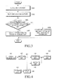
- FIG. 3 illustrates a method for controlling a wireless power receiver according to an embodiment of the present invention.
- the wireless power receiver receives wireless power from the wireless power transmitter in step S301.
- the wireless power receiver receives wireless power from the wireless power transmitter, for example, based on a resonance system.
- the wireless power received by the wireless power receiver is in an AC form with a certain voltage.
- the wireless power receiver rectifies the received wireless power in step S303.
- the wireless power receiver includes at least one diode such as a full-bridge diode, to rectify the received wireless power.
- the wireless power receiver determines whether the voltage of the rectified wireless power is equal to or higher than the allowable voltage of the charging unit in step S305.
- the wireless power receiver includes a voltage-comparing unit such as a comparator, and compares the voltage of the rectified wireless power to the allowable voltage of the charging unit.
- the wireless power receiver converts the voltage of the rectified wireless power to a voltage lower than the allowable voltage of the charging unit and outputs the wireless power to the charging unit in step S309. If the voltage of the rectified wireless power is lower than the allowable voltage of the charging unit in step S305-N, the wireless power receiver directly outputs the rectified wireless power to the charging unit in step S307.
- the voltage of the rectified wireless power is equal to or lower than the allowable voltage of the charging unit, converting is not performed. This prevents the loss of efficiency, which may occur in the converting process.
- FIG. 4 illustrates a wireless power receiver according to an embodiment of the present invention.
- the wireless power receiver 400 includes an electric power- receiving unit 410, a rectifying unit 420, a converting unit 430, a switching unit 440, a charging unit 450, and a control unit 460.
- the electric power-receiving unit 410 receives wireless power.
- the rectifying unit 420 rectifies the received wireless power to output DC wireless power.
- the converting unit 430 converts the voltage of the electric power rectified by the rectifying unit 420 to a predetermined voltage within the allowable voltage of the charging unit 450, and the converting unit 430 converts the voltage of the rectified electric power to 5 V, to prevent an excessive voltage from being applied to the charging unit 450.
- the switching unit 440 connects one end of the rectifying unit 420 and one end of the charging unit 450, and the one end of the rectifying unit 420 and the one end of the charging unit 450 are connected or disconnected according to the control of the control unit 460.
- the charging unit 450 stores wireless power converted by the converting unit 430 or stores wireless power directly output from the rectifying unit 420 by the switching unit 440.
- the control unit 460 controls the entire operations of the wireless power receiver 400.
- the control unit 460 monitors the voltage of the output terminal 421 of the rectifying unit 420. If the voltage at the output terminal 421 of the rectifying unit 420 is higher than the allowable voltage of the charging unit 450, the control unit 460 controls the converting unit 430 so that the voltage of the electric current output from the rectifying unit 420 is converted to a voltage lower than the allowable voltage. In addition, if the voltage at the output terminal 421 of the rectifying unit 420 is lower than the allowable voltage of the charging unit 450, the control unit 460 controls the switching unit 440 so that the wireless power output from the rectifying unit 420 is directly transmitted to the charging unit 450.
- the control unit 460 connects the switching unit 440. In addition, if the voltage at the output terminal 421 of the rectifying unit 420 is lower than the allowable voltage of the charging unit 450, the control unit 460 opens the switching unit 440.
- the control unit 460 compares the voltage at the output terminal 421 of the rectifying unit 420 and the allowable voltage based on information on the allowable voltage of the charging unit 450 read from the storage unit 470.
- the storage unit 470 includes information on the allowable voltage of the charging unit 450.
- the storage unit 470 stores programs, applications, and algorithms for the entire operation of the wireless power receiver 400 in addition to the allowable voltage of the charging unit 450.
- the storage unit 470 is realized by a volatile or non-volatile memory, and there is no limitation to the memory provided that the unit can store the allowable voltage information.
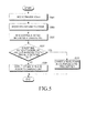
- FIG. 5 illustrates a method for controlling a wireless power receiver according to an embodiment of the present invention.
- the wireless power receiver receives wireless power from the wireless power transmitter in step S501, based on a resonance system, for example.
- the wireless power received by the wireless power receiver may have a DC form with a certain voltage.
- the wireless power receiver rectifies the received wireless power in step S503, and includes at least one diode such as a full-bridge diode, to rectify the received wireless power.
- the wireless power receiver reads previously stored information on the allowable voltage of the charging unit in step S505.
- the information on the allowable voltage of the charging unit relates to the maximum voltage that can be applied to the charging unit or a voltage to be preferably applied to the charging unit, for example.
- the wireless power receiver determines whether the voltage of the rectified wireless power is higher than the allowable voltage of the charging unit based on the read information on the allowable voltage of the charging unit in step S507.
- the wireless power receiver includes a voltage- comparing unit such as a comparator, and compares the voltage of the rectified wireless voltage and the allowable voltage of the charging unit.
- the wireless power receiver converts the voltage of the rectified wireless power to be lower than the allowable voltage of the charging unit and output the converted voltage to the charging unit in step S511. If the voltage of the rectified wireless power is lower than the allowable voltage of the charging unit (S507-N), the wireless power receiver directly outputs the rectified wireless power to the charging unit in step S509.
- the voltage of the rectified wireless power is lower than the allowable voltage of the charging unit, converting may not be performed. Accordingly, the loss of efficiency is prevented.
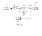
- FIG. 6 illustrates a wireless power receiver according to an embodiment of the present invention.
- a wireless power receiver 600 includes an electric power- receiving unit 610, a rectifying unit 620, a converting unit 630, a switching unit 640, a charging unit 650, and a control unit 660.
- the electric power-receiving unit 610 receives wireless power.
- the rectifying unit 620 rectifies the received wireless power to output DC wireless power.
- the converting unit 630 converts the voltage of the rectified electric power to the predetermined voltage by the rectifying unit 620.
- the converting unit 630 converts the voltage of the rectified electric power to a voltage within the allowable voltage of the charging unit 650, and the converting unit 630 converts the voltage of the rectified electric power to 5 V, for example.
- the converting unit 630 converts the voltage of the rectified electric power into a voltage within the allowable voltage of the charging unit 650 to prevent an excessive voltage from being applied to the charging unit 650.
- the switching unit 640 can connect one end of the rectifying unit 620 and one end of the charging unit 650, and connect or disconnect the one end of the rectifying unit 620 and one end of the charging unit 650 according to the control of the controlling unit 660.
- the charging unit 650 stores wireless power converted by the converting unit 630, or stores wireless power directly output from the rectifying unit 620 by the switching unit 640.
- the control unit 660 controls the entire operations of the wireless power receiver 600.
- the control unit 660 monitors the voltage of the output terminal 621 of the rectifying unit 620 and the electric current 652 flowing at an input terminal 651 of the charging unit 650.
- the control unit 660 performs control so that the switching unit 640 is open during a first period and the converting unit 630 converts the voltage of the rectified wireless power to a certain voltage and the converted wireless power is transmitted to the charging unit 650.
- the charging unit 650 receives wireless power wirelessly converted to a square waveform 652. More specifically, the charging unit 650 receives converted wireless power having a predetermined number of crests of square waves during the first period.
- the predetermined number of crests of the square waves corresponds to information on the allowable voltage of the charging unit 650. For example, if the allowable voltage of the charging unit 650 is 5 V, the charging unit 650 receives square waves having 5 crests during the first period.
- the number of crests of the square waves corresponds to the number of volts of the allowable voltage of the charging unit 650. Accordingly, for example, if the allowable voltage of the charging unit 650 is 4.5 V, the charging unit receives the square waves having 4 crests.
- the control unit 660 may recognize information on the allowable voltage of the charging unit 650 by the number of crests of the square waves input to the charging unit 650 during the first period.
- control unit 660 Based on the information on the allowable voltage of the charging unit 650 recognized in the first period, the control unit 660 performs control so that the rectified wireless power is converted or not converted and the wireless power is transmitted to the charging unit 650 during a second period. The operation of control unit 660 during the second period will be described.
- the control unit 660 controls the converting unit 630 so that the voltage of the electric current output from the rectifying unit 620 is converted to be lower than the allowable voltage. If the voltage at the output terminal 621 of the rectifying unit 620 is equal to or lower than the allowable voltage of the charging unit 650, the control unit 660 controls the switching 640 so that the wireless power output from the rectifying unit 620 is directly transferred to the charging unit 650.
- the control unit 660 connects the switching unit 640. If the voltage at the output terminal 621 of the rectifying unit 620 is lower than the allowable voltage of the charging unit 650, the control unit 660 opens the switching unit 640.
- FIG. 7 illustrates a method for controlling a wireless power receiver according to an embodiment of the present invention.
- the wireless power receiver receives wireless power from a wireless power transmitter in step S701, based on a resonance system, for example.
- the wireless power received by the wireless power receiver has an AC form having a certain voltage.
- the wireless power receiver rectifies the received wireless power in step S703.
- the wireless power receiver includes at least one diode such as a full-bridge diode, to rectify the received wireless power.
- the wireless power receiver may measure the electric current transferred to a charging unit at the front terminal of the charging unit in step S705.
- the electric current transferred to the charging unit may have a square waveform.
- the charging unit receives the converted wireless power having a predetermined number of crests of square waves, and the predetermined number of crests of the square waves corresponds to information on the allowable voltage of the charging unit. For example, if the allowable voltage of the charging unit is 5 V, the charging unit receives square waves having 5 crests during a first period.
- the information on the allowable voltage of the charging unit relates to the maximum voltage that can be applied to the charging unit or a voltage to be preferably applied to the charging unit, for example.
- the wireless power receiver determines whether the voltage of the rectified wireless power is equal to or higher than the allowable voltage of the charging unit based on the read information on the allowable voltage of the charging unit in step S707.
- the wireless power receiver includes a voltage-comparing unit such as a comparator, and compares the voltage of the rectified wireless voltage and the allowable voltage of the charging unit.
- the wireless power receiver converts the voltage of the rectified wireless power to be lower than the allowable voltage of the charging unit and output the converted voltage to the charging unit in step S711. If the voltage of the rectified wireless power is lower than the allowable voltage of the charging unit in step S707-N, the wireless power receiver may directly output the rectified wireless power to the charging unit in step S709.
- the voltage of the rectified wireless power is lower than the allowable voltage of the charging unit, converting is not performed. Accordingly, the loss of efficiency is prevented.
- FIG. 8 illustrates a wireless power receiver according to an embodiment of the present invention.
- a rectifying unit 801 realized by, for example, a bridge is connected by a node 802.
- the node 802 is connected to one end of a capacitor 803, and the other end of the capacitor 803 is connected to a ground 804.
- the node 802 is connected to other nodes 805, 806, and 807 which are connected to one end of diodes 808, 809, and 810, respectively.
- the other ends of the diodes 808, 809, and 810 are connected to a node 811.
- the node 811 is connected to an internal regulator 815.
- a first input (VLL) 812, a second input (VL) 813, and a third input (AVL) 814 are input to the internal regulator 815.
- the second input (VL) is connected to a PWM controller 816.
- the second input (VL) may have a connection 834 to the controller 836.
- the third connection (AVL) may have a connection to the PWM controller 816, and further a connection 833 to the controller 836.
- the controller 836 is connected to one end of diodes 838 and 839 and the other end of the diodes 838 and 839 is connected to a ground.
- the internal regulator 815 is connected to one end of the diode 861, and the other end of the diode 861 is connected to one end of the diode 862.
- the other end of the diode 862 is connected to one end of the capacitor 821, and the other end of the capacitor 821 is connected to a node 820.
- the node 820 is connected to one end of a coil 822 and one ends of the capacitors 819, 860, and 821.
- the other end of the capacitors 819, 860, and 821 is connected to a node 818.
- the nodes 811 and 818 are connected to a transistor 817, and a gate end of the transistor 817 is connected to the PWM controller 816.
- the node 818 is connected to a transistor 823, and a gate end of the transistor 823 is connected to a PWM controller 816.
- the transistor 823 is connected to one end of diodes 824, 825, and 826.
- the other end of the diodes 824, 825, and 826 is connected to ground 827.
- the other end of the coil 822 is connected to a node 828, which is connected to one end of a capacitor 829 and one end of diodes 830 and 831.
- the other end of the capacitor 829 is connected to a ground.
- the other end of the diodes 830 and 831 is connected to one end of the controller 836 and a resistance 832.
- the other end of the resistance 832 is connected to one end of the diodes 839 and 840 connected in parallel.
- the other end of the diodes 839 and 840 is connected to one end of the charging unit and the capacitor 841.
- the other end of the capacitor 841 is connected to a ground 842.
- the controller 836 receives various control signals 837, 838, 843, 844, 845, and 846.
Landscapes
- Engineering & Computer Science (AREA)
- Power Engineering (AREA)
- Computer Networks & Wireless Communication (AREA)
- Signal Processing (AREA)
- Charge And Discharge Circuits For Batteries Or The Like (AREA)
Applications Claiming Priority (1)
| Application Number | Priority Date | Filing Date | Title |
|---|---|---|---|
| KR1020120020336A KR101882800B1 (ko) | 2012-02-28 | 2012-02-28 | 무선 전력 수신기 및 그 제어 방법 |
Publications (3)
| Publication Number | Publication Date |
|---|---|
| EP2634892A2 true EP2634892A2 (fr) | 2013-09-04 |
| EP2634892A3 EP2634892A3 (fr) | 2018-01-03 |
| EP2634892B1 EP2634892B1 (fr) | 2019-11-20 |
Family
ID=47998145
Family Applications (1)
| Application Number | Title | Priority Date | Filing Date |
|---|---|---|---|
| EP13157128.3A Active EP2634892B1 (fr) | 2012-02-28 | 2013-02-28 | Récepteur de puissance sans fil et son procédé de commande |
Country Status (4)
| Country | Link |
|---|---|
| US (4) | US9685811B2 (fr) |
| EP (1) | EP2634892B1 (fr) |
| KR (1) | KR101882800B1 (fr) |
| CN (1) | CN103296786A (fr) |
Cited By (1)
| Publication number | Priority date | Publication date | Assignee | Title |
|---|---|---|---|---|
| US11539219B2 (en) | 2017-04-07 | 2022-12-27 | Guangdong Oppo Mobile Telecommunications Corp., Ltd. | Wireless charging device and method, and device to be charged |
Families Citing this family (16)
| Publication number | Priority date | Publication date | Assignee | Title |
|---|---|---|---|---|
| KR101882800B1 (ko) | 2012-02-28 | 2018-08-01 | 삼성전자주식회사 | 무선 전력 수신기 및 그 제어 방법 |
| US10014725B2 (en) | 2013-10-31 | 2018-07-03 | Ge Hybrid Technologies, Llc | Hybrid wireless power transmitting system and method therefor |
| US10177602B2 (en) | 2014-01-08 | 2019-01-08 | Mediatek Singapore Pte, Ltd. | Wireless power receiver with programmable power path |
| US20160268834A1 (en) * | 2014-01-08 | 2016-09-15 | Mediatek Inc. | Wireless power receiver with dynamically configurable power path |
| EP3108570B1 (fr) | 2014-02-19 | 2020-09-09 | Samsung Electronics Co., Ltd | Procédé pour détecter la charge dans une une opération de charge sans fil |
| US9635222B2 (en) | 2014-08-03 | 2017-04-25 | PogoTec, Inc. | Wearable camera systems and apparatus for aligning an eyewear camera |
| TWI584018B (zh) | 2014-08-03 | 2017-05-21 | 帕戈技術股份有限公司 | 穿戴式照相機系統與用於將照相機系統或其他電子裝置附接至穿戴式製品之設備及方法 |
| KR20170118054A (ko) | 2014-12-23 | 2017-10-24 | 포고텍, 인크. | 무선 카메라 시스템 및 방법들 |
| US10241351B2 (en) | 2015-06-10 | 2019-03-26 | PogoTec, Inc. | Eyewear with magnetic track for electronic wearable device |
| US10481417B2 (en) | 2015-06-10 | 2019-11-19 | PogoTec, Inc. | Magnetic attachment mechanism for electronic wearable device |
| CA3041583A1 (fr) | 2015-10-29 | 2017-05-04 | PogoTec, Inc. | Aide auditive concue pour une reception d'energie sans fil |
| US11558538B2 (en) | 2016-03-18 | 2023-01-17 | Opkix, Inc. | Portable camera system |
| EP3539285A4 (fr) | 2016-11-08 | 2020-09-02 | Pogotec, Inc. | Boîtier intelligent de dispositif électronique portatif |
| CN109417308B (zh) | 2017-04-07 | 2023-06-20 | Oppo广东移动通信有限公司 | 无线充电系统、装置、方法及待充电设备 |
| EP3462564A4 (fr) * | 2017-04-07 | 2019-05-08 | Guangdong Oppo Mobile Telecommunications Corp., Ltd. | Système, appareil et procédé de charge sans fil, et dispositif à charger |
| WO2020102237A1 (fr) | 2018-11-13 | 2020-05-22 | Opkix, Inc. | Supports portables pour appareil photo portable |
Family Cites Families (25)
| Publication number | Priority date | Publication date | Assignee | Title |
|---|---|---|---|---|
| JPS562717A (en) * | 1979-06-22 | 1981-01-13 | Hitachi Ltd | Magnetic amplifying unit |
| US5565756A (en) * | 1994-07-11 | 1996-10-15 | Motorola, Inc. | Microprocessor controlled portable battery charger and method of charging using same |
| US5568037A (en) * | 1995-04-03 | 1996-10-22 | Motorola, Inc. | Battery charging system having remotely located charging units |
| KR19980024391U (ko) * | 1996-10-31 | 1998-07-25 | 양재신 | 자동차용 변속레버 |
| EP0994878B1 (fr) | 1997-06-26 | 2001-11-28 | Dong Wha Pharmaceutical Industrial Co. Ltd. | Derives d'acide quinolonecarboxylique |
| US6252373B1 (en) * | 1999-04-26 | 2001-06-26 | Ion Control Solutions | Apparatus for rapidly charging and reconditioning a battery |
| JP2001309568A (ja) * | 2000-04-26 | 2001-11-02 | Internatl Business Mach Corp <Ibm> | 充電システム、充電制御装置、充電制御方法及びコンピュータ |
| EP1460519B1 (fr) * | 2003-03-18 | 2014-05-07 | Panasonic Corporation | Processeur, son procédé d'opération et dispositif de traitement d'informations |
| US7705565B2 (en) | 2003-12-31 | 2010-04-27 | Motorola, Inc. | Method and system for wireless charging |
| CN101156294B (zh) | 2005-04-28 | 2010-12-29 | 罗斯蒙德公司 | 现场设备用的充电系统 |
| JP2007221872A (ja) * | 2006-02-15 | 2007-08-30 | Ricoh Co Ltd | 二次電池の充電回路、二次電池の充電回路における電源切換方法及び電源装置 |
| CN101291073B (zh) | 2007-04-17 | 2011-05-04 | 台达电子工业股份有限公司 | 不断电电源供应器及其控制方法 |
| JP4805223B2 (ja) * | 2007-07-27 | 2011-11-02 | レノボ・シンガポール・プライベート・リミテッド | 充電システムおよび充電方法 |
| JP5413642B2 (ja) | 2009-01-30 | 2014-02-12 | 株式会社オートネットワーク技術研究所 | 電力供給制御回路 |
| KR20110008374A (ko) * | 2009-07-20 | 2011-01-27 | 김포대학산학협력단 | Rf 에너지 하베스팅 장치 |
| TW201136003A (en) * | 2009-09-30 | 2011-10-16 | Issc Technologies Corp | Wireless communication module |
| JP5499955B2 (ja) | 2009-10-05 | 2014-05-21 | Tdk株式会社 | ワイヤレス給電装置およびワイヤレス電力伝送システム |
| US8390249B2 (en) | 2009-11-30 | 2013-03-05 | Broadcom Corporation | Battery with integrated wireless power receiver and/or RFID |
| US9590444B2 (en) * | 2009-11-30 | 2017-03-07 | Broadcom Corporation | Device with integrated wireless power receiver configured to make a charging determination based on a level of battery life and charging efficiency |
| US20110127953A1 (en) * | 2009-11-30 | 2011-06-02 | Broadcom Corporation | Wireless power system |
| IT1400922B1 (it) | 2010-05-14 | 2013-07-02 | St Microelectronics Srl | Diodo di by-pass o interruttore per sorgente dc realizzato con un mosfet a bassa resistenza di conduzione e relativo circuito di controllo autoalimentato con mezzi di disabilitazione della sorgente dc in caso di incendio o altro rischio |
| US8390261B2 (en) | 2010-05-21 | 2013-03-05 | Infineon Technologies Austria Ag | Maximum power point tracker bypass |
| TW201238202A (en) * | 2011-03-11 | 2012-09-16 | Delta Electronics Inc | Charging apparatus of mobile vehicle |
| US20130026982A1 (en) * | 2011-07-29 | 2013-01-31 | Perry Rothenbaum | Wireless battery charging device, method and system |
| KR101882800B1 (ko) | 2012-02-28 | 2018-08-01 | 삼성전자주식회사 | 무선 전력 수신기 및 그 제어 방법 |
-
2012
- 2012-02-28 KR KR1020120020336A patent/KR101882800B1/ko active Active
-
2013
- 2013-02-27 US US13/779,207 patent/US9685811B2/en active Active
- 2013-02-28 CN CN2013100630302A patent/CN103296786A/zh active Pending
- 2013-02-28 EP EP13157128.3A patent/EP2634892B1/fr active Active
-
2017
- 2017-05-11 US US15/592,731 patent/US10432037B2/en active Active
-
2019
- 2019-09-30 US US16/587,692 patent/US10797538B2/en active Active
-
2020
- 2020-09-22 US US17/028,533 patent/US11043856B2/en active Active
Non-Patent Citations (1)
| Title |
|---|
| None |
Cited By (1)
| Publication number | Priority date | Publication date | Assignee | Title |
|---|---|---|---|---|
| US11539219B2 (en) | 2017-04-07 | 2022-12-27 | Guangdong Oppo Mobile Telecommunications Corp., Ltd. | Wireless charging device and method, and device to be charged |
Also Published As
| Publication number | Publication date |
|---|---|
| KR20130098649A (ko) | 2013-09-05 |
| US20130221914A1 (en) | 2013-08-29 |
| US11043856B2 (en) | 2021-06-22 |
| US10432037B2 (en) | 2019-10-01 |
| US10797538B2 (en) | 2020-10-06 |
| US9685811B2 (en) | 2017-06-20 |
| US20200028387A1 (en) | 2020-01-23 |
| EP2634892A3 (fr) | 2018-01-03 |
| KR101882800B1 (ko) | 2018-08-01 |
| CN103296786A (zh) | 2013-09-11 |
| US20210006100A1 (en) | 2021-01-07 |
| EP2634892B1 (fr) | 2019-11-20 |
| US20170250564A1 (en) | 2017-08-31 |
Similar Documents
| Publication | Publication Date | Title |
|---|---|---|
| US11043856B2 (en) | Wireless power receiver and controlling method thereof | |
| US11303135B2 (en) | Wireless power transmitter for excluding cross-connected wireless power receiver and method for controlling the same | |
| EP2587613B1 (fr) | Récepteur de puissance sans fil pour ajuster l'amplitude de puissance sans fil | |
| KR101950688B1 (ko) | 무선 전력 송신기 및 그 제어 방법 | |
| US9641019B2 (en) | Wireless power transmitter and method of controlling the same | |
| US10587123B2 (en) | Wireless power transmitter for excluding cross-connected wireless power receiver and method for controlling the same | |
| KR101962667B1 (ko) | 무선 전력 송신기, 무선 전력 수신기 및 각각의 제어 방법 | |
| US9780568B2 (en) | Wireless power receiver and method for controlling the same | |
| US9225195B2 (en) | Wireless power receiver for increased charging efficiency | |
| KR101893104B1 (ko) | 스위치를 이용하여 무선 전력을 조정하는 무선 전력 수신기 | |
| US20140184149A1 (en) | Method in wireless power transmission system, wireless power transmission apparatus using the same, and wireless power receiving apparatus using the same | |
| EP2720341B1 (fr) | Alimentation électrique sans fil, récepteur pour réguler sans fil la puissance électrique à l'aide d'un commutateur | |
| KR20140113147A (ko) | 무선 전력 전송 시스템에서 이물질 감지 장치 및 방법 |
Legal Events
| Date | Code | Title | Description |
|---|---|---|---|
| PUAI | Public reference made under article 153(3) epc to a published international application that has entered the european phase |
Free format text: ORIGINAL CODE: 0009012 |
|
| AK | Designated contracting states |
Kind code of ref document: A2 Designated state(s): AL AT BE BG CH CY CZ DE DK EE ES FI FR GB GR HR HU IE IS IT LI LT LU LV MC MK MT NL NO PL PT RO RS SE SI SK SM TR |
|
| AX | Request for extension of the european patent |
Extension state: BA ME |
|
| PUAL | Search report despatched |
Free format text: ORIGINAL CODE: 0009013 |
|
| AK | Designated contracting states |
Kind code of ref document: A3 Designated state(s): AL AT BE BG CH CY CZ DE DK EE ES FI FR GB GR HR HU IE IS IT LI LT LU LV MC MK MT NL NO PL PT RO RS SE SI SK SM TR |
|
| AX | Request for extension of the european patent |
Extension state: BA ME |
|
| RIC1 | Information provided on ipc code assigned before grant |
Ipc: H02J 7/00 20060101ALI20171129BHEP Ipc: H02J 7/02 20160101AFI20171129BHEP |
|
| STAA | Information on the status of an ep patent application or granted ep patent |
Free format text: STATUS: REQUEST FOR EXAMINATION WAS MADE |
|
| 17P | Request for examination filed |
Effective date: 20180410 |
|
| RBV | Designated contracting states (corrected) |
Designated state(s): AL AT BE BG CH CY CZ DE DK EE ES FI FR GB GR HR HU IE IS IT LI LT LU LV MC MK MT NL NO PL PT RO RS SE SI SK SM TR |
|
| STAA | Information on the status of an ep patent application or granted ep patent |
Free format text: STATUS: EXAMINATION IS IN PROGRESS |
|
| 17Q | First examination report despatched |
Effective date: 20190103 |
|
| GRAP | Despatch of communication of intention to grant a patent |
Free format text: ORIGINAL CODE: EPIDOSNIGR1 |
|
| STAA | Information on the status of an ep patent application or granted ep patent |
Free format text: STATUS: GRANT OF PATENT IS INTENDED |
|
| INTG | Intention to grant announced |
Effective date: 20190606 |
|
| GRAS | Grant fee paid |
Free format text: ORIGINAL CODE: EPIDOSNIGR3 |
|
| GRAA | (expected) grant |
Free format text: ORIGINAL CODE: 0009210 |
|
| STAA | Information on the status of an ep patent application or granted ep patent |
Free format text: STATUS: THE PATENT HAS BEEN GRANTED |
|
| AK | Designated contracting states |
Kind code of ref document: B1 Designated state(s): AL AT BE BG CH CY CZ DE DK EE ES FI FR GB GR HR HU IE IS IT LI LT LU LV MC MK MT NL NO PL PT RO RS SE SI SK SM TR |
|
| REG | Reference to a national code |
Ref country code: GB Ref legal event code: FG4D |
|
| REG | Reference to a national code |
Ref country code: CH Ref legal event code: EP |
|
| REG | Reference to a national code |
Ref country code: IE Ref legal event code: FG4D |
|
| REG | Reference to a national code |
Ref country code: DE Ref legal event code: R096 Ref document number: 602013063020 Country of ref document: DE |
|
| REG | Reference to a national code |
Ref country code: AT Ref legal event code: REF Ref document number: 1205295 Country of ref document: AT Kind code of ref document: T Effective date: 20191215 |
|
| REG | Reference to a national code |
Ref country code: NL Ref legal event code: MP Effective date: 20191120 |
|
| REG | Reference to a national code |
Ref country code: LT Ref legal event code: MG4D |
|
| PG25 | Lapsed in a contracting state [announced via postgrant information from national office to epo] |
Ref country code: NO Free format text: LAPSE BECAUSE OF FAILURE TO SUBMIT A TRANSLATION OF THE DESCRIPTION OR TO PAY THE FEE WITHIN THE PRESCRIBED TIME-LIMIT Effective date: 20200220 Ref country code: GR Free format text: LAPSE BECAUSE OF FAILURE TO SUBMIT A TRANSLATION OF THE DESCRIPTION OR TO PAY THE FEE WITHIN THE PRESCRIBED TIME-LIMIT Effective date: 20200221 Ref country code: BG Free format text: LAPSE BECAUSE OF FAILURE TO SUBMIT A TRANSLATION OF THE DESCRIPTION OR TO PAY THE FEE WITHIN THE PRESCRIBED TIME-LIMIT Effective date: 20200220 Ref country code: SE Free format text: LAPSE BECAUSE OF FAILURE TO SUBMIT A TRANSLATION OF THE DESCRIPTION OR TO PAY THE FEE WITHIN THE PRESCRIBED TIME-LIMIT Effective date: 20191120 Ref country code: FI Free format text: LAPSE BECAUSE OF FAILURE TO SUBMIT A TRANSLATION OF THE DESCRIPTION OR TO PAY THE FEE WITHIN THE PRESCRIBED TIME-LIMIT Effective date: 20191120 Ref country code: LV Free format text: LAPSE BECAUSE OF FAILURE TO SUBMIT A TRANSLATION OF THE DESCRIPTION OR TO PAY THE FEE WITHIN THE PRESCRIBED TIME-LIMIT Effective date: 20191120 Ref country code: NL Free format text: LAPSE BECAUSE OF FAILURE TO SUBMIT A TRANSLATION OF THE DESCRIPTION OR TO PAY THE FEE WITHIN THE PRESCRIBED TIME-LIMIT Effective date: 20191120 Ref country code: LT Free format text: LAPSE BECAUSE OF FAILURE TO SUBMIT A TRANSLATION OF THE DESCRIPTION OR TO PAY THE FEE WITHIN THE PRESCRIBED TIME-LIMIT Effective date: 20191120 Ref country code: ES Free format text: LAPSE BECAUSE OF FAILURE TO SUBMIT A TRANSLATION OF THE DESCRIPTION OR TO PAY THE FEE WITHIN THE PRESCRIBED TIME-LIMIT Effective date: 20191120 |
|
| PG25 | Lapsed in a contracting state [announced via postgrant information from national office to epo] |
Ref country code: IS Free format text: LAPSE BECAUSE OF FAILURE TO SUBMIT A TRANSLATION OF THE DESCRIPTION OR TO PAY THE FEE WITHIN THE PRESCRIBED TIME-LIMIT Effective date: 20200320 Ref country code: HR Free format text: LAPSE BECAUSE OF FAILURE TO SUBMIT A TRANSLATION OF THE DESCRIPTION OR TO PAY THE FEE WITHIN THE PRESCRIBED TIME-LIMIT Effective date: 20191120 Ref country code: RS Free format text: LAPSE BECAUSE OF FAILURE TO SUBMIT A TRANSLATION OF THE DESCRIPTION OR TO PAY THE FEE WITHIN THE PRESCRIBED TIME-LIMIT Effective date: 20191120 |
|
| PG25 | Lapsed in a contracting state [announced via postgrant information from national office to epo] |
Ref country code: AL Free format text: LAPSE BECAUSE OF FAILURE TO SUBMIT A TRANSLATION OF THE DESCRIPTION OR TO PAY THE FEE WITHIN THE PRESCRIBED TIME-LIMIT Effective date: 20191120 |
|
| PG25 | Lapsed in a contracting state [announced via postgrant information from national office to epo] |
Ref country code: CZ Free format text: LAPSE BECAUSE OF FAILURE TO SUBMIT A TRANSLATION OF THE DESCRIPTION OR TO PAY THE FEE WITHIN THE PRESCRIBED TIME-LIMIT Effective date: 20191120 Ref country code: RO Free format text: LAPSE BECAUSE OF FAILURE TO SUBMIT A TRANSLATION OF THE DESCRIPTION OR TO PAY THE FEE WITHIN THE PRESCRIBED TIME-LIMIT Effective date: 20191120 Ref country code: PT Free format text: LAPSE BECAUSE OF FAILURE TO SUBMIT A TRANSLATION OF THE DESCRIPTION OR TO PAY THE FEE WITHIN THE PRESCRIBED TIME-LIMIT Effective date: 20200412 Ref country code: EE Free format text: LAPSE BECAUSE OF FAILURE TO SUBMIT A TRANSLATION OF THE DESCRIPTION OR TO PAY THE FEE WITHIN THE PRESCRIBED TIME-LIMIT Effective date: 20191120 Ref country code: DK Free format text: LAPSE BECAUSE OF FAILURE TO SUBMIT A TRANSLATION OF THE DESCRIPTION OR TO PAY THE FEE WITHIN THE PRESCRIBED TIME-LIMIT Effective date: 20191120 |
|
| REG | Reference to a national code |
Ref country code: AT Ref legal event code: MK05 Ref document number: 1205295 Country of ref document: AT Kind code of ref document: T Effective date: 20191120 |
|
| REG | Reference to a national code |
Ref country code: DE Ref legal event code: R097 Ref document number: 602013063020 Country of ref document: DE |
|
| PG25 | Lapsed in a contracting state [announced via postgrant information from national office to epo] |
Ref country code: SM Free format text: LAPSE BECAUSE OF FAILURE TO SUBMIT A TRANSLATION OF THE DESCRIPTION OR TO PAY THE FEE WITHIN THE PRESCRIBED TIME-LIMIT Effective date: 20191120 Ref country code: SK Free format text: LAPSE BECAUSE OF FAILURE TO SUBMIT A TRANSLATION OF THE DESCRIPTION OR TO PAY THE FEE WITHIN THE PRESCRIBED TIME-LIMIT Effective date: 20191120 |
|
| REG | Reference to a national code |
Ref country code: DE Ref legal event code: R119 Ref document number: 602013063020 Country of ref document: DE |
|
| PLBE | No opposition filed within time limit |
Free format text: ORIGINAL CODE: 0009261 |
|
| STAA | Information on the status of an ep patent application or granted ep patent |
Free format text: STATUS: NO OPPOSITION FILED WITHIN TIME LIMIT |
|
| REG | Reference to a national code |
Ref country code: CH Ref legal event code: PL |
|
| 26N | No opposition filed |
Effective date: 20200821 |
|
| REG | Reference to a national code |
Ref country code: BE Ref legal event code: MM Effective date: 20200229 |
|
| PG25 | Lapsed in a contracting state [announced via postgrant information from national office to epo] |
Ref country code: LU Free format text: LAPSE BECAUSE OF NON-PAYMENT OF DUE FEES Effective date: 20200228 Ref country code: MC Free format text: LAPSE BECAUSE OF FAILURE TO SUBMIT A TRANSLATION OF THE DESCRIPTION OR TO PAY THE FEE WITHIN THE PRESCRIBED TIME-LIMIT Effective date: 20191120 |
|
| PG25 | Lapsed in a contracting state [announced via postgrant information from national office to epo] |
Ref country code: AT Free format text: LAPSE BECAUSE OF FAILURE TO SUBMIT A TRANSLATION OF THE DESCRIPTION OR TO PAY THE FEE WITHIN THE PRESCRIBED TIME-LIMIT Effective date: 20191120 Ref country code: PL Free format text: LAPSE BECAUSE OF FAILURE TO SUBMIT A TRANSLATION OF THE DESCRIPTION OR TO PAY THE FEE WITHIN THE PRESCRIBED TIME-LIMIT Effective date: 20191120 Ref country code: CH Free format text: LAPSE BECAUSE OF NON-PAYMENT OF DUE FEES Effective date: 20200229 Ref country code: SI Free format text: LAPSE BECAUSE OF FAILURE TO SUBMIT A TRANSLATION OF THE DESCRIPTION OR TO PAY THE FEE WITHIN THE PRESCRIBED TIME-LIMIT Effective date: 20191120 Ref country code: LI Free format text: LAPSE BECAUSE OF NON-PAYMENT OF DUE FEES Effective date: 20200229 |
|
| PG25 | Lapsed in a contracting state [announced via postgrant information from national office to epo] |
Ref country code: FR Free format text: LAPSE BECAUSE OF NON-PAYMENT OF DUE FEES Effective date: 20200229 Ref country code: IE Free format text: LAPSE BECAUSE OF NON-PAYMENT OF DUE FEES Effective date: 20200228 Ref country code: IT Free format text: LAPSE BECAUSE OF FAILURE TO SUBMIT A TRANSLATION OF THE DESCRIPTION OR TO PAY THE FEE WITHIN THE PRESCRIBED TIME-LIMIT Effective date: 20191120 Ref country code: DE Free format text: LAPSE BECAUSE OF NON-PAYMENT OF DUE FEES Effective date: 20200901 |
|
| PG25 | Lapsed in a contracting state [announced via postgrant information from national office to epo] |
Ref country code: BE Free format text: LAPSE BECAUSE OF NON-PAYMENT OF DUE FEES Effective date: 20200229 |
|
| PG25 | Lapsed in a contracting state [announced via postgrant information from national office to epo] |
Ref country code: TR Free format text: LAPSE BECAUSE OF FAILURE TO SUBMIT A TRANSLATION OF THE DESCRIPTION OR TO PAY THE FEE WITHIN THE PRESCRIBED TIME-LIMIT Effective date: 20191120 Ref country code: MT Free format text: LAPSE BECAUSE OF FAILURE TO SUBMIT A TRANSLATION OF THE DESCRIPTION OR TO PAY THE FEE WITHIN THE PRESCRIBED TIME-LIMIT Effective date: 20191120 Ref country code: CY Free format text: LAPSE BECAUSE OF FAILURE TO SUBMIT A TRANSLATION OF THE DESCRIPTION OR TO PAY THE FEE WITHIN THE PRESCRIBED TIME-LIMIT Effective date: 20191120 |
|
| PG25 | Lapsed in a contracting state [announced via postgrant information from national office to epo] |
Ref country code: MK Free format text: LAPSE BECAUSE OF FAILURE TO SUBMIT A TRANSLATION OF THE DESCRIPTION OR TO PAY THE FEE WITHIN THE PRESCRIBED TIME-LIMIT Effective date: 20191120 |
|
| PGFP | Annual fee paid to national office [announced via postgrant information from national office to epo] |
Ref country code: GB Payment date: 20260122 Year of fee payment: 14 |