EP2634912A2 - Verfahren zur Steuerung eines Umrichters - Google Patents
Verfahren zur Steuerung eines Umrichters Download PDFInfo
- Publication number
- EP2634912A2 EP2634912A2 EP13156775.2A EP13156775A EP2634912A2 EP 2634912 A2 EP2634912 A2 EP 2634912A2 EP 13156775 A EP13156775 A EP 13156775A EP 2634912 A2 EP2634912 A2 EP 2634912A2
- Authority
- EP
- European Patent Office
- Prior art keywords
- pwm
- inverter
- pulses
- frequency
- present disclosure
- Prior art date
- Legal status (The legal status is an assumption and is not a legal conclusion. Google has not performed a legal analysis and makes no representation as to the accuracy of the status listed.)
- Withdrawn
Links
Images

Classifications
-
- H—ELECTRICITY
- H02—GENERATION; CONVERSION OR DISTRIBUTION OF ELECTRIC POWER
- H02M—APPARATUS FOR CONVERSION BETWEEN AC AND AC, BETWEEN AC AND DC, OR BETWEEN DC AND DC, AND FOR USE WITH MAINS OR SIMILAR POWER SUPPLY SYSTEMS; CONVERSION OF DC OR AC INPUT POWER INTO SURGE OUTPUT POWER; CONTROL OR REGULATION THEREOF
- H02M7/00—Conversion of AC power input into DC power output; Conversion of DC power input into AC power output
- H02M7/42—Conversion of DC power input into AC power output without possibility of reversal
- H02M7/44—Conversion of DC power input into AC power output without possibility of reversal by static converters
- H02M7/48—Conversion of DC power input into AC power output without possibility of reversal by static converters using discharge tubes with control electrode or semiconductor devices with control electrode
-
- H—ELECTRICITY
- H02—GENERATION; CONVERSION OR DISTRIBUTION OF ELECTRIC POWER
- H02P—CONTROL OR REGULATION OF ELECTRIC MOTORS, ELECTRIC GENERATORS OR DYNAMO-ELECTRIC CONVERTERS; CONTROLLING TRANSFORMERS, REACTORS OR CHOKE COILS
- H02P27/00—Arrangements or methods for the control of AC motors characterised by the kind of supply voltage
- H02P27/04—Arrangements or methods for the control of AC motors characterised by the kind of supply voltage using variable-frequency supply voltage, e.g. inverter or converter supply voltage
- H02P27/06—Arrangements or methods for the control of AC motors characterised by the kind of supply voltage using variable-frequency supply voltage, e.g. inverter or converter supply voltage using DC to AC converters or inverters
- H02P27/08—Arrangements or methods for the control of AC motors characterised by the kind of supply voltage using variable-frequency supply voltage, e.g. inverter or converter supply voltage using DC to AC converters or inverters with pulse width modulation
-
- H—ELECTRICITY
- H02—GENERATION; CONVERSION OR DISTRIBUTION OF ELECTRIC POWER
- H02M—APPARATUS FOR CONVERSION BETWEEN AC AND AC, BETWEEN AC AND DC, OR BETWEEN DC AND DC, AND FOR USE WITH MAINS OR SIMILAR POWER SUPPLY SYSTEMS; CONVERSION OF DC OR AC INPUT POWER INTO SURGE OUTPUT POWER; CONTROL OR REGULATION THEREOF
- H02M1/00—Details of apparatus for conversion
- H02M1/12—Arrangements for reducing harmonics from AC input or output
-
- H—ELECTRICITY
- H02—GENERATION; CONVERSION OR DISTRIBUTION OF ELECTRIC POWER
- H02M—APPARATUS FOR CONVERSION BETWEEN AC AND AC, BETWEEN AC AND DC, OR BETWEEN DC AND DC, AND FOR USE WITH MAINS OR SIMILAR POWER SUPPLY SYSTEMS; CONVERSION OF DC OR AC INPUT POWER INTO SURGE OUTPUT POWER; CONTROL OR REGULATION THEREOF
- H02M1/00—Details of apparatus for conversion
- H02M1/14—Arrangements for reducing ripples from DC input or output
-
- H—ELECTRICITY
- H02—GENERATION; CONVERSION OR DISTRIBUTION OF ELECTRIC POWER
- H02M—APPARATUS FOR CONVERSION BETWEEN AC AND AC, BETWEEN AC AND DC, OR BETWEEN DC AND DC, AND FOR USE WITH MAINS OR SIMILAR POWER SUPPLY SYSTEMS; CONVERSION OF DC OR AC INPUT POWER INTO SURGE OUTPUT POWER; CONTROL OR REGULATION THEREOF
- H02M7/00—Conversion of AC power input into DC power output; Conversion of DC power input into AC power output
- H02M7/42—Conversion of DC power input into AC power output without possibility of reversal
- H02M7/44—Conversion of DC power input into AC power output without possibility of reversal by static converters
- H02M7/48—Conversion of DC power input into AC power output without possibility of reversal by static converters using discharge tubes with control electrode or semiconductor devices with control electrode
- H02M7/53—Conversion of DC power input into AC power output without possibility of reversal by static converters using discharge tubes with control electrode or semiconductor devices with control electrode using devices of a triode or transistor type requiring continuous application of a control signal
- H02M7/537—Conversion of DC power input into AC power output without possibility of reversal by static converters using discharge tubes with control electrode or semiconductor devices with control electrode using devices of a triode or transistor type requiring continuous application of a control signal using semiconductor devices only, e.g. single switched pulse inverters
- H02M7/539—Conversion of DC power input into AC power output without possibility of reversal by static converters using discharge tubes with control electrode or semiconductor devices with control electrode using devices of a triode or transistor type requiring continuous application of a control signal using semiconductor devices only, e.g. single switched pulse inverters with automatic control of output wave form or frequency
- H02M7/5395—Conversion of DC power input into AC power output without possibility of reversal by static converters using discharge tubes with control electrode or semiconductor devices with control electrode using devices of a triode or transistor type requiring continuous application of a control signal using semiconductor devices only, e.g. single switched pulse inverters with automatic control of output wave form or frequency by pulse-width modulation
-
- H—ELECTRICITY
- H02—GENERATION; CONVERSION OR DISTRIBUTION OF ELECTRIC POWER
- H02P—CONTROL OR REGULATION OF ELECTRIC MOTORS, ELECTRIC GENERATORS OR DYNAMO-ELECTRIC CONVERTERS; CONTROLLING TRANSFORMERS, REACTORS OR CHOKE COILS
- H02P23/00—Arrangements or methods for the control of AC motors characterised by a control method other than vector control
- H02P23/0086—Arrangements or methods for the control of AC motors characterised by a control method other than vector control specially adapted for high speeds, e.g. above nominal speed
-
- H—ELECTRICITY
- H02—GENERATION; CONVERSION OR DISTRIBUTION OF ELECTRIC POWER
- H02P—CONTROL OR REGULATION OF ELECTRIC MOTORS, ELECTRIC GENERATORS OR DYNAMO-ELECTRIC CONVERTERS; CONTROLLING TRANSFORMERS, REACTORS OR CHOKE COILS
- H02P2209/00—Indexing scheme relating to controlling arrangements characterised by the waveform of the supplied voltage or current
- H02P2209/09—PWM with fixed limited number of pulses per period
Definitions
- the present disclosure relates to a method for controlling an inverter.
- a motor is used for driving a turbo machine. Revolution of a motor is in proportion to a frequency of a supplied power, and in reverse proportion to the number of poles, such that a maximum revolution cannot exceed 3,600 rpm for a two-poled motor. A mechanical step-up gearbox is needed to obtain a speed higher than the 3,600 rpm.
- cost disadvantageously increases and a machined efficiency decreases due to mechanical friction loss.
- a high-speed motor capable of obtaining a high efficiency at a high speed is recently used, and in order to increase revolution of the high speed motor, a technique to increase a motor speed up to several ten thousands of rpm has been commercialized.
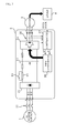
- FIG.1 is a schematic configuration of a motor system controlled by a conventional inverter.
- a motor system includes an AC (Alternating Current) power source (1), an inverter (2) controlling a motor (3), the motor (3) and a load (4).
- AC Alternating Current
- the inverter (2) includes a converter (21) converting an AC power source to a DC power source, an initial charging resistor (22) preventing inflow of inrush current in a case a power source is inputted, a switch (23) separating the initial charging resistor (22) from a circuit after the inrush current is prevented, a capacitor (24) smoothing a DC voltage, a PWM (Pulse Width Modulation) inverter unit (25) formed with a plurality of switching devices to convert a DC current to an AC current, a current detection unit (26) detecting a current flowing in U, V and W phase, a controller (27) collecting various information including a DC voltage and a phase current of the inverter (2), and a PWM controller (28) generating a PWM signal using a voltage command V* inputted from the controller (27) and a frequency command f* and applying a switching signal to a switching device of each phase of the PWM inverter unit (25).
- a converter (21) converting an AC power source to a
- the load (4) is driven by the motor (3), where the load (4) receives a load amount and transmits the load amount to the controller (27).
- the inverter (2) of FIG.1 receives a power of the AC power source (1), converts the voltage and the frequency through a power conversion and supplies the converted voltage and frequency to the motor (3), whereby speed and torque of the motor (3) can be controlled at a high efficiency.
- accurate control of motor speed can realize energy saving and quality improvement, such that the inverter (2) is widely used in automotive facilities including various blowers, pumps, machine tools and textile machines.
- a Sinusoidal PWM (SPWM) control is widely used for a PWM controller (28) of FIG.1 to generate a PWM signal.
- SPWM control an output signal is outputted by comparing a sinusoidal reference signal with a triangular (saw-tooth) wave carrier.
- a slow speed inverter 60 Hz or less
- an inverter can be operated using asynchronous SPWM without any great change in the number of pulses.
- a high speed inverter suffers from a disadvantage in that the number of PWM pulses is greatly changed in response to a high speed change (several kHz) in inverter operation frequency.
- the high speed inverter fails to receive a predetermined output current, disadvantageously making it impossible to obtain a stable inverter output due to increase in pulsation of output current.
- Methods and systems consistent with the present disclosure provide a method for controlling an inverter configured to obtain a stable output current in a high speed inverter by performing a synchronous PWM control.
- a method for controlling an inverter comprising: calculating the number of PWM pulses from a current frequency of the inverter; compensating the number of PWM pulses using a predetermined number of pulses when the number of PWM pulses is less than the predetermined number of pulses; and calculating a new frequency of the inverter using the compensated number of PWM pulses.
- the method may further comprise outputting a PWM pulse in response to the new frequency.
- the PWM pulse outputted by the new frequency is a synchronous PWM pulse.
- the method may further comprise performing asynchronous PWM control when the inverter is under a slow speed operation mode.
- the method may further comprise performing asynchronous PWM control when the inverter is under asynchronous PWM operation mode.
- the method for controlling an inverter according to exemplary embodiments of the present disclosure has an advantageous effect in that the number of PWM output pulses is so controlled as to allow the PWM output pulses to synchronize in symmetrical manner, to thereby obtain a distortion-free stable output current during a high speed operation of an inverter.
- the method for controlling an inverter according to the present disclosure is applicable to cases where the inverter is operated, whose rated speed reaches several thousand rpm and whose operation frequency reaches several kHz, as in high speed blowers and high speed refrigerators.
- the present disclosure performs a symmetric PWM control during an inverter PWM control to stabilize an inverter output current during high speed switching in response to increase in operation frequency.
- the method for controlling an inverter according to the present disclosure is applicable to an inverter system as shown in FIG.1 , and particularly to a control of a PWM controller (28).
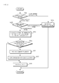
- FIG.2 is a flowchart illustrating a method for an inverter according to the present disclosure.
- the method for controlling an inverter is to check an operation mode of an inverter (S21), and to perform an asymmetrical PWM control for a low speed operation (S23).
- S21 operation mode of an inverter
- S23 low speed operation
- asymmetrical PWM control a sinusoidal reference signal and a triangular carrier are compared to output an output voltage.
- the PWM controller (28) checks a predetermined PWM mode (S22). To this end, the inverter may designate and store whether to operate under a synchronous PWM mode or under an asynchronous PWM mode in response to a user designation.
- the PWM controller (28) performs an asynchronous PWM control (S23), and performs a synchronous PWM control, in case of the predetermined PWM mode being a synchronous PWM mode.
- the PWM controller (28) calculates the number of PWM pulses based on a current output frequency of the inverter (S24).
- the PWM controller (28) compensates the number of PWM pulses using a predetermined number of pulses (S26) when the number of PWM pulses calculated at S24 is less than the predetermined number of pulses.
- the PWM controller (28) now calculates a new output frequency (S27) using the compensated number of PWM pulses, and outputs a PWM pulse using the calculated new frequency (S28).
- FIG.3 is a graph illustrating a synchronous PWM control according to the present disclosure, where (a) defines a relationship between a sinusoidal reference signal and a triangular carrier, (b) defines a PWM pulse outputted by a conventional sinusoidal reference signal (A), and (c) defines a PWM pulse outputted by a sinusoidal reference signal (B) compensated in terms of the number of PWM pulses according to the present disclosure.
- the number of PWM pulses is greatly changed by changes in rapidly-changing frequency during high speed operation of an inverter, and an output waveform is greatly influenced by increase and decrease in the number of PWM pulses.
- the PWM controller (28) calculates a PWM pulse of a currently operated inverter, compensates a value of the calculated PWM pulse, in a case the number of PWM pulses is less than a predetermined number of pulses, and controls a synchronous PWM by changing an operation frequency of the inverter.
- a distortion-free stable output current can be obtained during high speed operation of an inverter by controlling the number of PWM pulses by allowing the PWM pulses to be symmetrically synchronized.
Landscapes
- Engineering & Computer Science (AREA)
- Power Engineering (AREA)
- Control Of Ac Motors In General (AREA)
- Inverter Devices (AREA)
Applications Claiming Priority (1)
| Application Number | Priority Date | Filing Date | Title |
|---|---|---|---|
| KR1020120021639A KR101300380B1 (ko) | 2012-03-02 | 2012-03-02 | 인버터 제어방법 |
Publications (2)
| Publication Number | Publication Date |
|---|---|
| EP2634912A2 true EP2634912A2 (de) | 2013-09-04 |
| EP2634912A3 EP2634912A3 (de) | 2017-09-13 |
Family
ID=47749709
Family Applications (1)
| Application Number | Title | Priority Date | Filing Date |
|---|---|---|---|
| EP13156775.2A Withdrawn EP2634912A3 (de) | 2012-03-02 | 2013-02-26 | Verfahren zur Steuerung eines Umrichters |
Country Status (5)
| Country | Link |
|---|---|
| US (1) | US9093944B2 (de) |
| EP (1) | EP2634912A3 (de) |
| JP (1) | JP5841088B2 (de) |
| KR (1) | KR101300380B1 (de) |
| CN (1) | CN103296963B (de) |
Families Citing this family (5)
| Publication number | Priority date | Publication date | Assignee | Title |
|---|---|---|---|---|
| JP6425819B2 (ja) * | 2015-08-12 | 2018-11-21 | 三菱電機株式会社 | 電動機駆動装置および冷凍空調装置 |
| CN105422432B (zh) * | 2015-12-08 | 2017-06-13 | 卧龙电气集团股份有限公司 | 多模式智能水泵变频监控系统 |
| CN109429541B (zh) | 2016-09-29 | 2021-06-11 | 富士电机株式会社 | 逆变器的控制方法、控制装置及逆变器 |
| KR20190105372A (ko) * | 2018-03-05 | 2019-09-17 | 엘지전자 주식회사 | 압축기 제어장치 및 이의 압축기 제어방법 |
| EP3657670B1 (de) * | 2018-11-26 | 2022-12-28 | KEB Automation KG | Verfahren sowie vorrichtung zur fehlersicheren drehzahlüberwachung |
Citations (1)
| Publication number | Priority date | Publication date | Assignee | Title |
|---|---|---|---|---|
| US20110127937A1 (en) * | 2008-10-17 | 2011-06-02 | Toyota Jidosha Kabushiki Kaisha | Motor actuation control device |
Family Cites Families (22)
| Publication number | Priority date | Publication date | Assignee | Title |
|---|---|---|---|---|
| US3611086A (en) * | 1970-01-14 | 1971-10-05 | Reliance Electric Co | Integral carrier ratio inverter |
| US3662247A (en) * | 1970-10-01 | 1972-05-09 | Reliance Electric Co | Pulse width modulated inverter adaptive logic |
| US3886430A (en) * | 1973-12-06 | 1975-05-27 | Reliance Electric Co | Phase and frequency synchronizing circuit |
| JPH0779551B2 (ja) * | 1987-03-20 | 1995-08-23 | 株式会社日立製作所 | インバ−タ制御装置 |
| JPH0720374B2 (ja) | 1987-06-01 | 1995-03-06 | 株式会社日立製作所 | インバ−タ制御装置 |
| JP2814837B2 (ja) * | 1992-06-04 | 1998-10-27 | 株式会社日立製作所 | 電力変換装置 |
| US5585709A (en) | 1993-12-22 | 1996-12-17 | Wisconsin Alumni Research Foundation | Method and apparatus for transducerless position and velocity estimation in drives for AC machines |
| JP3233005B2 (ja) * | 1996-03-01 | 2001-11-26 | 株式会社日立製作所 | Pwm制御装置 |
| JPH1075586A (ja) | 1996-08-29 | 1998-03-17 | Toyo Electric Mfg Co Ltd | 同期式pwmのデッドタイム補償装置 |
| JP4062949B2 (ja) | 2002-04-02 | 2008-03-19 | 三菱電機株式会社 | 可変速制御装置 |
| JP2004274905A (ja) | 2003-03-10 | 2004-09-30 | Toshiba Mitsubishi-Electric Industrial System Corp | 直流電動機の制御装置 |
| JP4601044B2 (ja) | 2004-08-30 | 2010-12-22 | 日立アプライアンス株式会社 | 電力変換装置およびその電力変換装置を備えた空気調和機 |
| JP4556572B2 (ja) * | 2004-09-09 | 2010-10-06 | アイシン・エィ・ダブリュ株式会社 | 電動駆動制御装置、電動駆動制御方法及びプログラム |
| US7626836B2 (en) * | 2005-10-26 | 2009-12-01 | Rockwell Automation Technologies, Inc. | Method and apparatus for adjustable voltage/adjustable frequency inverter control |
| GB2441359B (en) * | 2006-09-02 | 2011-08-03 | Converteam Ltd | Control methods for pulse width modulation (PWM) |
| JP4901517B2 (ja) * | 2007-02-08 | 2012-03-21 | 株式会社東芝 | 交流電動機制御装置 |
| JP4707740B2 (ja) * | 2007-07-26 | 2011-06-22 | 三菱電機株式会社 | 電力変換装置 |
| US8222857B2 (en) * | 2007-09-25 | 2012-07-17 | Mitsubishi Electric Corporation | Motor controlling device |
| JP2009284598A (ja) | 2008-05-20 | 2009-12-03 | Toshiba Corp | 交流電動機の制御装置 |
| EP2340957B1 (de) * | 2008-10-23 | 2018-08-29 | Mitsubishi Electric Corporation | Antriebssteuervorrichtung für elektroauto |
| US8258735B2 (en) * | 2008-12-15 | 2012-09-04 | Mitsubishi Electric Corporation | Power converting apparatus for motor driving |
| JP5762241B2 (ja) * | 2010-12-01 | 2015-08-12 | 株式会社ダイヘン | 電源装置及びアーク加工用電源装置 |
-
2012
- 2012-03-02 KR KR1020120021639A patent/KR101300380B1/ko active Active
-
2013
- 2013-02-26 EP EP13156775.2A patent/EP2634912A3/de not_active Withdrawn
- 2013-02-27 US US13/779,663 patent/US9093944B2/en active Active
- 2013-03-01 JP JP2013040846A patent/JP5841088B2/ja not_active Expired - Fee Related
- 2013-03-04 CN CN201310067970.9A patent/CN103296963B/zh active Active
Patent Citations (1)
| Publication number | Priority date | Publication date | Assignee | Title |
|---|---|---|---|---|
| US20110127937A1 (en) * | 2008-10-17 | 2011-06-02 | Toyota Jidosha Kabushiki Kaisha | Motor actuation control device |
Also Published As
| Publication number | Publication date |
|---|---|
| US9093944B2 (en) | 2015-07-28 |
| CN103296963A (zh) | 2013-09-11 |
| JP5841088B2 (ja) | 2016-01-06 |
| JP2013183636A (ja) | 2013-09-12 |
| EP2634912A3 (de) | 2017-09-13 |
| US20130229845A1 (en) | 2013-09-05 |
| KR101300380B1 (ko) | 2013-08-29 |
| CN103296963B (zh) | 2017-03-29 |
Similar Documents
| Publication | Publication Date | Title |
|---|---|---|
| KR101245961B1 (ko) | 전력 변환 장치 | |
| JP3955286B2 (ja) | モータ駆動用インバータ制御装置および空気調和機 | |
| US9214881B2 (en) | Power conversion apparatus | |
| US9960703B2 (en) | DC power-supply device and refrigeration-cycle application device including the same | |
| US9093944B2 (en) | Method for controlling PWM inverter by compensating the number of PWM pulses in response to frequency change | |
| CN101277059B (zh) | 电力变换装置 | |
| US20130307463A1 (en) | Power conversion apparatus, power conversion method, motor system, and two-phase induction motor | |
| JP5807156B2 (ja) | モータ駆動用インバータ制御回路および電気掃除機 | |
| EP2595298B1 (de) | Gleichrichter | |
| JP2015116092A (ja) | 電動車両 | |
| US9543849B2 (en) | Power conversion apparatus, power conversion method, motor system, and three-phase motor | |
| JP2015159646A (ja) | モータ制御システム | |
| JP4755504B2 (ja) | 電力変換装置 | |
| WO2013179771A1 (ja) | コンバータ装置及び、これを用いたモータ駆動装置 | |
| KR20180120520A (ko) | 고압인버터 제어 방법 및 이를 포함하는 시스템 | |
| CN110677096B (zh) | 驱动控制装置、变频器及驱动控制方法 | |
| JP5734626B2 (ja) | 電源装置および空気調和機 | |
| JP2010124585A (ja) | モータ駆動用インバータ制御装置およびそれを備えた空気調和機 | |
| JP2002374696A (ja) | モータの駆動装置 | |
| JP2008043048A (ja) | モータ駆動用インバータ制御装置 | |
| KR101893240B1 (ko) | 인버터 제어장치 | |
| JP2021044909A (ja) | 電源装置、制御方法、及びプログラム | |
| JP2012205423A (ja) | モータの制御装置 | |
| JP2006246667A (ja) | 電動機駆動装置 | |
| JP2005312202A (ja) | モータ駆動用インバータ制御装置およびそれを用いた電気機器 |
Legal Events
| Date | Code | Title | Description |
|---|---|---|---|
| PUAI | Public reference made under article 153(3) epc to a published international application that has entered the european phase |
Free format text: ORIGINAL CODE: 0009012 |
|
| AK | Designated contracting states |
Kind code of ref document: A2 Designated state(s): AL AT BE BG CH CY CZ DE DK EE ES FI FR GB GR HR HU IE IS IT LI LT LU LV MC MK MT NL NO PL PT RO RS SE SI SK SM TR |
|
| AX | Request for extension of the european patent |
Extension state: BA ME |
|
| PUAL | Search report despatched |
Free format text: ORIGINAL CODE: 0009013 |
|
| AK | Designated contracting states |
Kind code of ref document: A3 Designated state(s): AL AT BE BG CH CY CZ DE DK EE ES FI FR GB GR HR HU IE IS IT LI LT LU LV MC MK MT NL NO PL PT RO RS SE SI SK SM TR |
|
| AX | Request for extension of the european patent |
Extension state: BA ME |
|
| RIC1 | Information provided on ipc code assigned before grant |
Ipc: H02M 1/32 20070101ALN20170807BHEP Ipc: H02P 23/00 20160101AFI20170807BHEP Ipc: H02P 27/08 20060101ALI20170807BHEP Ipc: H02M 1/00 20070101ALN20170807BHEP |
|
| 17P | Request for examination filed |
Effective date: 20180309 |
|
| RBV | Designated contracting states (corrected) |
Designated state(s): AL AT BE BG CH CY CZ DE DK EE ES FI FR GB GR HR HU IE IS IT LI LT LU LV MC MK MT NL NO PL PT RO RS SE SI SK SM TR |
|
| 17Q | First examination report despatched |
Effective date: 20191122 |
|
| STAA | Information on the status of an ep patent application or granted ep patent |
Free format text: STATUS: THE APPLICATION IS DEEMED TO BE WITHDRAWN |
|
| 18D | Application deemed to be withdrawn |
Effective date: 20201119 |