EP2635738B1 - Système d'alimentation en papier et procédé d'alimentation en papier - Google Patents
Système d'alimentation en papier et procédé d'alimentation en papier Download PDFInfo
- Publication number
- EP2635738B1 EP2635738B1 EP11837319.0A EP11837319A EP2635738B1 EP 2635738 B1 EP2635738 B1 EP 2635738B1 EP 11837319 A EP11837319 A EP 11837319A EP 2635738 B1 EP2635738 B1 EP 2635738B1
- Authority
- EP
- European Patent Office
- Prior art keywords
- paper
- barrier
- feeder
- assembly
- rotatable elements
- Prior art date
- Legal status (The legal status is an assumption and is not a legal conclusion. Google has not performed a legal analysis and makes no representation as to the accuracy of the status listed.)
- Not-in-force
Links
- 238000000034 method Methods 0.000 title claims description 14
- 230000004888 barrier function Effects 0.000 claims description 32
- 238000007599 discharging Methods 0.000 claims description 17
- 230000001105 regulatory effect Effects 0.000 claims description 12
- 230000004044 response Effects 0.000 claims description 6
- 230000001276 controlling effect Effects 0.000 claims description 5
- 238000011143 downstream manufacturing Methods 0.000 claims description 3
- 238000011144 upstream manufacturing Methods 0.000 claims description 3
- 230000007246 mechanism Effects 0.000 description 12
- 239000000463 material Substances 0.000 description 7
- 239000000428 dust Substances 0.000 description 2
- 239000010899 old newspaper Substances 0.000 description 2
- XLYOFNOQVPJJNP-UHFFFAOYSA-N water Substances O XLYOFNOQVPJJNP-UHFFFAOYSA-N 0.000 description 2
- 230000009471 action Effects 0.000 description 1
- 238000004140 cleaning Methods 0.000 description 1
- 230000005574 cross-species transmission Effects 0.000 description 1
- 230000001419 dependent effect Effects 0.000 description 1
- 238000010586 diagram Methods 0.000 description 1
- 230000006870 function Effects 0.000 description 1
- 230000005484 gravity Effects 0.000 description 1
- 230000006872 improvement Effects 0.000 description 1
- 238000002955 isolation Methods 0.000 description 1
- 230000008569 process Effects 0.000 description 1
- 239000002994 raw material Substances 0.000 description 1
- 238000010408 sweeping Methods 0.000 description 1
Images



Classifications
-
- B—PERFORMING OPERATIONS; TRANSPORTING
- B65—CONVEYING; PACKING; STORING; HANDLING THIN OR FILAMENTARY MATERIAL
- B65G—TRANSPORT OR STORAGE DEVICES, e.g. CONVEYORS FOR LOADING OR TIPPING, SHOP CONVEYOR SYSTEMS OR PNEUMATIC TUBE CONVEYORS
- B65G47/00—Article or material-handling devices associated with conveyors; Methods employing such devices
- B65G47/02—Devices for feeding articles or materials to conveyors
- B65G47/16—Devices for feeding articles or materials to conveyors for feeding materials in bulk
- B65G47/18—Arrangements or applications of hoppers or chutes
- B65G47/19—Arrangements or applications of hoppers or chutes having means for controlling material flow, e.g. to prevent overloading
-
- B—PERFORMING OPERATIONS; TRANSPORTING
- B65—CONVEYING; PACKING; STORING; HANDLING THIN OR FILAMENTARY MATERIAL
- B65G—TRANSPORT OR STORAGE DEVICES, e.g. CONVEYORS FOR LOADING OR TIPPING, SHOP CONVEYOR SYSTEMS OR PNEUMATIC TUBE CONVEYORS
- B65G47/00—Article or material-handling devices associated with conveyors; Methods employing such devices
- B65G47/22—Devices influencing the relative position or the attitude of articles during transit by conveyors
- B65G47/26—Devices influencing the relative position or the attitude of articles during transit by conveyors arranging the articles, e.g. varying spacing between individual articles
- B65G47/28—Devices influencing the relative position or the attitude of articles during transit by conveyors arranging the articles, e.g. varying spacing between individual articles during transit by a single conveyor
- B65G47/29—Devices influencing the relative position or the attitude of articles during transit by conveyors arranging the articles, e.g. varying spacing between individual articles during transit by a single conveyor by temporarily stopping movement
-
- D—TEXTILES; PAPER
- D21—PAPER-MAKING; PRODUCTION OF CELLULOSE
- D21B—FIBROUS RAW MATERIALS OR THEIR MECHANICAL TREATMENT
- D21B1/00—Fibrous raw materials or their mechanical treatment
- D21B1/04—Fibrous raw materials or their mechanical treatment by dividing raw materials into small particles, e.g. fibres
- D21B1/06—Fibrous raw materials or their mechanical treatment by dividing raw materials into small particles, e.g. fibres by dry methods
- D21B1/08—Fibrous raw materials or their mechanical treatment by dividing raw materials into small particles, e.g. fibres by dry methods the raw material being waste paper; the raw material being rags
-
- Y—GENERAL TAGGING OF NEW TECHNOLOGICAL DEVELOPMENTS; GENERAL TAGGING OF CROSS-SECTIONAL TECHNOLOGIES SPANNING OVER SEVERAL SECTIONS OF THE IPC; TECHNICAL SUBJECTS COVERED BY FORMER USPC CROSS-REFERENCE ART COLLECTIONS [XRACs] AND DIGESTS
- Y02—TECHNOLOGIES OR APPLICATIONS FOR MITIGATION OR ADAPTATION AGAINST CLIMATE CHANGE
- Y02W—CLIMATE CHANGE MITIGATION TECHNOLOGIES RELATED TO WASTEWATER TREATMENT OR WASTE MANAGEMENT
- Y02W30/00—Technologies for solid waste management
- Y02W30/50—Reuse, recycling or recovery technologies
- Y02W30/64—Paper recycling
Definitions
- the invention concerns feeding paper in a processing system.
- raw material in the form of recyclable paper and old newspaper (“ONP") and the like is fed to a grinder which grinds the paper before the ground material is mixed with water.
- the resulting particulate, or pulp is then subjected to further processing depending on the product to be formed from the recycled paper.
- An object of the invention is to provide an improvement over prior art. This object is achieved by a method and an assembly as set forth in the appended independent claims; preferred embodiments being defined in the appended dependent claims.
- a method of feeding paper through a paper feeder by conveying paper along a path and regulating the through-flow of paper from the path to dispense the paper from the feeder at a controlled flow rate while continuously moving the paper to avoid blockages.
- the method includes regulating the flow of paper by conveying the paper up and over a barrier in the path, which is a wall of rotatable elements arranged in horizontal banks and driven to convey the paper up and over the wall by traction.
- the rotatable elements are mounted on a common shaft in each bank and are horizontally staggered relative to the rotatable elements in the bank immediately above and below. The rotatable elements are rotated in the same rotational direction.
- the method includes conveying paper at a controlled flow rate in response to feedback to a controller from sensors positioned along the path, and sensing the amount of paper entering the paper feeder and the amount of paper discharging the paper feeder.
- the method includes adjusting the speed of a conveyor on which the paper is conveyed, in response to the sensors.
- the method may include further regulating the flow of paper by conveying the paper under a barrier.
- the barrier sweeps back a build up of paper being conveyed.
- a sensor upstream of the barrier senses a build up of paper by way of the sweeping back of paper by the barrier and, through a controller, adjusts the flow rate of paper being conveyed.
- an assembly for a paper feeder comprising a holding container having an inlet through which paper is deposited, a conveyor for moving the paper in the holding container towards a discharge outlet, and a regulator for regulating the through-flow of paper from the conveyor to dispense through the discharge outlet at a controlled flow rate while continuously moving the paper to avoid blockages.
- the regulator is a barrier up and over which the paper is conveyed by traction.
- the barrier is a wall of rotatable elements which are arranged in horizontal banks and which are driven to rotate in the same rotational direction to move the paper up and over the wall, and toward the discharge outlet.
- the rotatable elements are mounted on a common shaft in each bank and are horizontally staggered relative to the elements in the bank immediately above and below.
- the paper feeder may further comprise a control system for controlling the flow rate of paper through the paper feeder in response to feedback from sensors positioned in the paper feeder and/or in a downstream process from the paper feeder.
- the barrier may be positioned inside the holding container and at the end of an endless belt conveyor that conveys paper towards the discharge outlet.
- the wall of rotatable elements may be inclined vertically against a direction of flow of the paper to encourage continuous flow of paper up the barrier and avoid blockages.
- Each rotatable element may comprise at least two engageable portions to enable each element to be individually mounted onto, and dismounted from, a shaft.
- the paper feeder may also include a tipper comprising at least one bank of rotatable elements and positioned near an upper end of the barrier whereby the elements are driven to rotate to assist in conveying the paper over the barrier.
- the rotatable elements comprise an annular 'star'-shaped disc whereby the spikes defining the star points catch the paper to convey the paper upwardly.
- the container may comprise a discharge head, in which the regulator is mounted.
- the discharge head may comprise a hood, positioned over the regulator.
- the rotatable elements of the tipper may counter rotate relative to the rotatable elements of the wall.
- the rotatable elements may rotate at a greater speed of rotation relative to the rotatable elements of the wall, as controlled by the controller and depending on the feedback from the sensors.
- the angle between adjacent sides of each spike alternate between approximately 90° and approximately 45°.
- the assembly may comprise a mounting member for each rotatable element to attach to so as to mount the element to a rotatable shaft.
- Each rotatable element may comprise two or more portions, separately mountable to each element's respective mounting member.
- Each mounting member may comprise two or more mounting portions, fastenable together to form the mounting member.
- Each mounting member may comprise a casing portion for encasing a portion of the rotatable shaft which the rotatable element is to be mounted to.
- Each mounting portion may comprise one or more tabs for the rotatable elements to be fastened to.
- the mounting portions may comprise a plurality of grooves formed in each shaft, a respective groove in each mounting member, and a plurality of keys, each key comprising a rod receivable in a groove of one of the shafts and the corresponding groove of one of the mounting portions to prevent the mounting portions from rotating relative to their respective shafts.
- the endless belt conveyor may move about at least two rollers.
- One roller may be a variable drive roller.
- the speed of the belt may be varied by the controller to control the discharge rate of the discharger.
- the assembly may also comprise a maximum flow limiter in the form of a regulating barrier under which the paper is conveyed, and which limits the flow of paper being fed by the assembly to a downstream paper processing system.
- a maximum flow limiter in the form of a regulating barrier under which the paper is conveyed, and which limits the flow of paper being fed by the assembly to a downstream paper processing system.
- the maximum flow limiter may be located downstream of the discharger and may comprise a carrier, or a conveyor, configured to receive and move paper discharged by the wall of rotating elements and a barrier located relative to the carrier to define a space between the barrier and the carrier through which the carrier carries paper. The space limits the maximum volume of paper exiting the assembly relative to the speed the carrier moves the paper.
- the carrier may be a conveyor, which may be the same conveyor that moves paper to the discharge outlet, or may be independent of that conveyor.
- the barrier may comprise a plate member, or paddle, mounted above the carrier.
- the plate member may be configured to rotate, preferably continuously, so as to send excess paper back in the opposite direction to which the paper is being carried by the carrier.
- the maximum flow limiter may comprise a housing for housing the barrier and at least part of the carrier.
- the paper feeder may further comprise a control system for controlling the operation of the feeder, the control system comprising a filling control for controlling the filling of the container with paper, a discharging control for controlling the discharging of the paper from the container and a controller for operating the control system.
- a control system for controlling the operation of the feeder, the control system comprising a filling control for controlling the filling of the container with paper, a discharging control for controlling the discharging of the paper from the container and a controller for operating the control system.
- the filling control may comprise a container level sensor for detecting the amount of paper in the container.
- the discharging control may comprise a surge point volume sensor for detecting the volume of material exiting the container.
- the discharging control may also comprise the maximum flow limiter, if present in the assembly.
- the discharging control may comprise a current load sensor for detecting the current load on a motor driving a grinder of the paper processing system, the grinder grinding the paper fed from the paper feeder.
- the discharging control may comprise a discharge level sensor for detecting the level of paper discharged from the container onto a feed conveyor to the paper processing system.
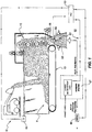
- an assembly 10 (a paper feeder) for feeding paper to a recyclable paper processing system at a controlled rate.
- the assembly 10 comprises generally a container 11 for holding a mass of paper, a regulator for regulating the through-flow of discharging paper from the container 11 through a discharge outlet 81.
- the form the regulator takes in the embodiment described and illustrated is referred to as a 'discharger' 12 as that device is located to discharge paper through the outlet 81.
- a moving mechanism 13, or a conveyor conveys the mass of paper towards the discharger 12.
- the assembly 10 operates to dispense paper through the outlet at a controlled flow rate while continuously moving the paper to avoid blockages.
- a large mass of paper can be deposited into the container and the through-flow of paper regulated by the discharger before exiting through a discharge outlet at a controlled and constant pace.
- This avoids the need of a dedicated person manually and continuously feeding the paper feeder to avoid build up of paper at the discharge outlet, which is a constriction and a typically point of jamming.
- the method of feeding paper through the paper feed assembly is by conveying paper along a path and regulating the through-flow of paper to dispense the paper from the feeder at a controlled flow rate while continuously moving the paper to avoid blockages.
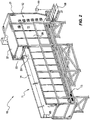
- the container 11 may be described as a bin or hopper and comprises an open feed trough 14 at one end and a discharge head 15 at an opposing end.
- the moving mechanism 13 in the form of a conveyor is located inside the container 11. Paper which might be old newspaper ("ONP") or any other paper is cleaned to remove any foreign material before being periodically loaded into the trough 14 on top of the conveyor (moving mechanism 13) as required in order to provide a sufficient mass of paper in the container 11.
- the discharger 12 is mounted in the discharge head 15 of the container 11, the discharge head 15 receiving paper from the trough 14 as it is moved by the moving mechanism 13.
- the discharge head 15 has a hood positioned over the discharger 12.
- the hood partially encloses the discharger 12 to reduce the spread of dust from the assembly 10 by the discharging process.
- the discharge head 15 comprises side walls 20, an end wall 21 opposing the opening in the discharger head through which paper is moved by the moving mechanism, a roof 22 and an overhang 23 opposing the end wall 21.
- the roof 22 and the overhang 23 form the hood of the discharge head 15.
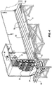
- the discharger 12 comprises a plurality of rotatable elements 30 which engage pieces of paper in the paper mass to move the pieces of paper to discharge the paper from the container 11 as they rotate.
- the discharger 12 comprises a wall 32 of these elements 30 arranged in a number of banks, with each element in a bank mounted on a common rotatable shaft 33.
- the wall 32 forms a barrier at the end of the container 11 to the exit from the container 11 for the mass of paper.
- the discharger 12 operates to regulate the through-flow of paper being conveyed by moving pieces of paper by traction from one side of the wall 32 to the other side to discharge the paper from the container 11 through an outlet 81 at the bottom of the container 11. Discharged paper is taken from the outlet 81 to the downstream units of recyclable paper processing system by for example a feed conveyor 68 as shown in the Figures.
- each bank of the wall 32 overlap in the horizontal and vertical planes with the elements in the banks above and below. Namely, the elements are staggered with respect to those in the banks immediately above and below. This is to prevent paper from inadvertently slipping between the elements in the wall 32 to bypass the discharger 12 and exit the container 11. It also means that the elements are self-cleaning in that the spaces between horizontally adjacent elements are kept free of paper by the vertically adjacent elements, ensuring that paper does not accumulate and jam between the shafts 33.
- Each bank of elements in the wall 32 is positioned horizontally closer to the moving mechanism 13 than the banks vertically below, ie. is positioned closer to the end of the container 11 furthest from the discharger 12.
- the wall 32 is angled or inclined vertically against the direction of paper flow and towards the moving mechanism 13 (and towards the end of the container 11 furthest from the discharger 12). The purpose of this is to ensure that the discharger does not "pick up” the whole mass of paper in the container 11, but rather a generally even draw of paper is taken vertically from the mass of paper to be discharged from the container 11.
- the force of the mass of paper being conveyed against the discharger 12 assists in ensuring an even draw of paper is taken up by the discharger.
- the wall 32 comprises six banks of eight elements 30. However, it is understood that the wall 32 may comprise more or less banks and that each bank may comprise more or less elements. In general, the wider the container 11, the more the number of elements 30 required in each bank so as to ensure that there are no "gaps" in the wall 32 for paper to inadvertently slip through. In addition, the wall 32 needs to be higher than the height of the open feed trough 14 of the container 11 so that paper doesn't readily spill over the wall.
- the banks of elements in the wall 32 are driven to rotate by a common drive 34 and thus, in use, have a common rotational speed. However, if desired, separate drives can be provided for one or more of the banks.
- the discharger 12 also comprises a tipper 35 for assisting the paper engaged by the elements of the wall 32 in being tipped over the top of the wall 32.
- the tipper 35 also serves to prevent paper lifted up by the elements of the wall 32 from falling back under its own weight.
- the tipper 35 comprises at least one bank of the rotatable elements 30 described above.
- the tipper 35 is located in the container 11 and positioned upwardly and inwardly from the wall 32.
- the elements of the tipper 35 are arranged to counter rotate to the elements of the wall 32.
- the elements of the tipper 35 also rotate at a slightly greater speed than the elements of the wall 32 so as to "flick" the paper at the top of the wall 32 over the top of the wall 32.
- An additional drive 36 is provided to rotate the tipper 35.
- Each element 30 comprises a generally annular and flat disc having a plurality of rounded spikes 31 for engaging, or catching, pieces of paper at the bottom of their path of rotation, effectively "picking up” the pieces of paper.
- the tips of the spikes are sufficiently pointed to impart traction, or grip, on the moving paper, but not so pointed so as to pierce the paper, which would make removal therefrom difficult.
- the elements As the elements rotate 30, they lift the pieces of paper engaged by the spikes and push them onto the elements above. This movement of paper occurs substantially vertically up the inclined wall 32 until the pieces of paper reach the uppermost bank of elements of the wall. As these uppermost elements rotate, the pieces of paper engaged thereto, are pulled "over" the wall (with the assistance of the tipper 35). On the other side of the wall, the pieces of paper disengage from the spikes of the elements under gravity and fall to the container outlet.
- the spikes 31 each comprise an outward projecting triangular segment and are arranged such that every alternate angle between the sides of adjacent spikes is approximately 90° while the other angles between adjacent spikes are 45°. In the representations shown in the drawings, this arrangement creates an element with eight spikes. Each spike has a circular pitch of approximately 45°. The spikes 31 of each element are shaped in this way so as to provide good vertical conveying of the paper whilst retaining sufficient strength to maintain integrity under load.
- Each element 30 comprises eight spikes 31, although it is understood that they could comprise more or less spikes.
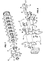
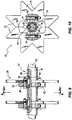
- the shafts 33 extend through the annulus of each element attached thereto. To facilitate selective attachment and removal from the shafts 33, each element 30 is split into two or more portions (as shown in particular in Figures 7 and 8 ). Should one of the elements or a portion of one of the elements be damaged, worn or otherwise require replacement, the affected portion(s) can be readily detached from the shaft without requiring the wall 32 or one of the banks to be completely disassembled.
- the discharger 12 comprises a plurality of mounting members 37 or hubs mounted to the shaft 33.
- the mounting members 37 are provided with apertures 38 for receiving fasteners (for example bolts or screws) to fasten an element 30 to the mounting member.
- Corresponding apertures 39 are provided in each of the elements 30.
- the apertures 38 for fastening the elements to respective mounting members 37 are parallel to the longitudinal axis of the shaft 33.
- Each mounting member 37 comprises at least two mounting portions 40 which can be mounted to one of the shafts 33.
- Each mounting portion 40 is generally identical and comprises a casing portion 41 for encasing a portion of one of the shafts 33 and one or more tabs 42 in which the apertures 38 are formed to receive fasteners to fasten an element 30 to the mounting member.
- the casing portions are semi-cylindrical in shape, but may be of any other suitable shape which generally conforms with a portion of the outer surface of the shafts 33.
- At least two of the tabs 42 of each of the mounting portions 40 are arranged to abut tabs of adjacent mounting portions.
- Apertures 43 are provided in the abutting tabs for receiving fasteners to fasten the mounting portions together. These apertures 43 are transverse to the longitudinal axis of the shaft 33. Fastening the mounting portions 40 together in this manner provides a clamping action about the shaft which acts against the mounting members 37 from moving axially with respect to their respective shaft 33.
- the mounting members 37 are prevented from rotating relative to their respective shaft 33 by way of a key and groove arrangement.
- Each shaft 33 is provided with a plurality of grooves 44 generally extending along the length of the shaft, each groove corresponding to one of the elements 30 to be mounted to that shaft.
- a corresponding groove 45 is provided in one of the mounting portions 40.
- a key in the form of a rectangular rod 46 is positioned in the space formed between the respective groove 44 in the shaft and the groove 45 in the mounting portion. Assembly of each mounting member 37 occurs by first positioning its respective rod 46 in its respective groove 34 in the shaft 33 prior to placing the mounting portions 40 around the shaft 33 with the groove 45 formed in one of the mounting portions 40 aligned to fit over the rod 46.
- the mounting portions 40 are subsequently fixed in this arrangement by use of the fasteners and apertures described above. Although only one mounting portion in each of the mounting members is shown in the Figures as having a groove, it is to be understood that in other embodiments all of the mounting portions could have a groove.
- the moving mechanism 13 is shown in the Figures in the form of an endless belt 50 located at the bottom of the container 11.
- the endless belt 50 is substantially horizontal, but may be inclined.
- the endless belt has a plurality of ridges or bars 51 provided on its outer surface for pulling along the paper sitting on the belt so that the paper moves with the movement of the belt.
- the endless belt 50 moves about at least two rollers 52, one of which is a variable drive roller.
- the speed of the endless belt 50 is used to control the amount of paper discharged from the container 11 by varying the speed of the drive roller and hence the speed of the endless belt 50, whilst the rotational speed of the elements 30 of the discharger remains substantially constant.
- the speed of the endless belt 50 By changing the speed of the endless belt 50, the amount of paper which is "pushed” onto the elements 30 and thus lifted over the wall 32 is varied. This enables simple control of the rate of paper discharged from the container 11 and thus fed to the recyclable paper processing system.
- Mechanisms other than the endless belt may be provided to (variably) move the paper towards the discharger.
- the moving mechanism 13 may comprise a plate on the end of a ram which extends from the distal end of the container 11 to the discharger 12 to push paper in the container towards the discharger.
- FIG. 1 illustrates a control system 60 which can be used to control the operation of the assembly 10.
- the control system 60 comprises a filling control 61 for the control of the filling of the container 11 with paper and a discharging control 62 for the control of the discharging of paper from the container 11 using the discharger 12.
- the control system 60 also comprises a controller (PLC) 63 for operating the control system 60 including storing and using any algorithms for operating the assembly 10.
- the controller 63 operates both the filling control 61 and the discharging control 62.
- the filling control 61 comprises a container level sensor 65 for detecting the amount of paper in the container 11.
- the container level sensor 65 is positioned towards the top of the container 11, level with the uppermost shaft 33 in the wall 32 of the discharger 12. Initially, the container 11 is filled with paper at least to the level of the container level senor 65. As the moving mechanism 13 moves the paper towards the discharger 12, the paper inside the container moves horizontally as a bulk (as opposed to paper being pulled from the top or the bottom). Thus, the container level sensor 65 detects the horizontal position of the bulk of paper relative to the distal end of the container 11 by measuring the distance of the moving bulk of paper from the end of the container.
- the controller 63 When the sensor 65 detects that the bulk of paper has reached a predetermined horizontal position within the container, the controller 63 signals an indicator such as an alarm to indicate that the container 11 requires filling with paper in order to maintain momentum, or the moving force, of the bulk of paper against the discharger 12. Filling of the container is carried out manually using for example a front end loader as illustrated in Figure 1 .
- the discharging control 62 has three control points which are associated with the recyclable paper processing system to which the discharger is discharging paper:
- Information from these three control points is used by the controller 63 to determine whether the endless belt 50 of the moving mechanism 13 should move faster or slower so as to discharge more or less paper from the container 11 into the feed to the recyclable paper processing system. Priority is given to the volume of material at the surge point 66 to ensure that the amount of material fed to the rest of the recyclable paper processing system from the grinder is substantially constant. In doing this, optimum operation of the recyclable paper processing system can be obtained.
- a maximum flow limiter 70 is shown which may further regulate the flow rate of paper being dispensed to the recyclable paper processing system.
- the maximum flow limiter 70 may be incorporated into the assembly 10 as part of the discharging control 62.
- the maximum flow limiter 70 limits the maximum flow of paper being fed by the assembly 10 to the downstream recyclable paper processing system and is located between the discharger 12 and a discharge outlet of the assembly (not shown) from where paper is fed to the processing system. This helps prevent overfeeding of paper to the processing system.
- the maximum flow limiter 70 comprises a carrier configured to receive and move paper discharged by the discharger and a barrier located relative to the carrier to define a space between the barrier and the carrier through which the carrier carries the paper. The space limits the maximum volume of paper exiting the assembly relative to the speed the carrier moves the paper.
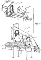
- the carrier of the maximum flow limiter is a form of conveyor and could be an extension of the endless belt 50 in a preferred embodiment shown in Figure 11 , in the embodiment shown the carrier is feed conveyor 68, which is independent of the endless belt 50.
- the barrier of the maximum flow limiter 70 comprises a plate member 71, or paddle, which is operated to rotate on a shaft above the feed conveyor 68.
- the plate member 71 rotates so as to "flick” or “sweep” excess paper back along the feed conveyor 68 in the opposite direction to which it is being carried, and namely upstream relative to the direction of flow along the flow path. Any paper below the rotating edge of the plate member 71 is allowed to pass under the plate member and is fed to the recyclable paper processing system downstream. By flicking excess paper back along the conveyor, the rotating plate member prevents a build up of excess paper around the barrier which, if it occurred, could result in the maximum flow limiter jamming.
- the barrier could comprise a fixed plate positioned above the feed conveyor 68. In this variation a space is defined between the bottom edge of the fixed plate and the top surface of the conveyor through which the conveyor carries recyclable paper.
- the maximum flow limiter 70 also comprises a housing 72 which houses the rotating plate member 71 and at least part of the feed conveyor 68.
- the housing 72 prevents paper from being thrown off the feed conveyor 68 as well as minimising the spread of dust from the maximum flow limiter.
- the discharge level sensor 69 mentioned above, is mounted to the housing 72 of the maximum flow limiter 70.
- the discharge level 69 is positioned relative to the rotating plate 71 to appropriately monitor the build up of any paper on the feed conveyor 68 which is being flicked back by the rotating plate; which would indicate that excessive paper is being discharged from the container 11 by the discharger 12. In these circumstances, the discharge level sensor 69 would indicate, via the controller 63, to slow the movement of the endless belt 50. Accordingly, the maximum flow limiter 70 provides an internal control for the assembly 10 to prevent runaway of how much paper is discharged by the discharger 12.
- the flow of paper from the assembly 10 is smoothed and in particular spikes of high flow are prevented. This makes operation of the downstream processing system easier and places less stress on the system.
Landscapes
- Engineering & Computer Science (AREA)
- Mechanical Engineering (AREA)
- Life Sciences & Earth Sciences (AREA)
- Wood Science & Technology (AREA)
- Paper (AREA)
- Delivering By Means Of Belts And Rollers (AREA)
Claims (11)
- Procédé d'alimentation en papier par l'intermédiaire d'un dispositif d'alimentation en papier (10) en transportant du papier le long d'un chemin et régulant l'écoulement traversant de papier depuis le chemin pour distribuer le papier depuis le dispositif d'alimentation à un débit commandé tout déplaçant en continu le papier afin d'éviter des blocages ; et transportant le papier vers le haut et par-dessus une barrière (32) dans le chemin afin de réguler l'écoulement de papier ;
caractérisé en ce que la barrière (32) est une paroi d'éléments rotatifs (30) qui sont entraînés pour transporter le papier par traction vers le haut et par-dessus la paroi, lesdits éléments rotatifs (30) étant agencés par blocs horizontaux ; dans lequel les éléments rotatifs (30) sont montés sur un arbre commun (33) dans chaque bloc et sont horizontalement décalés par rapport aux éléments rotatifs dans le bloc juste au-dessus et au-dessous ; et dans lequel les éléments rotatifs (30) tournent dans la même direction de rotation. - Procédé selon la revendication 1, incluant le transport de papier à un débit commandé en réponse à un retour à un système de commande (60) provenant de moyens formant capteur (65, 69) positionnés le long du chemin.
- Procédé selon la revendication 1 ou 2, incluant en outre la régulation de l'écoulement de papier évacué du dispositif d'alimentation en papier en transportant le papier sous une barrière mobile (71) qui balaie toute accumulation de papier qui est évacué.
- Procédé selon les revendications 2 et 3, dans lequel un capteur (69) en amont de la barrière mobile (71) détecte une accumulation de papier balayé par la barrière mobile (71) et, par l'intermédiaire du système de commande (60), ajuste le débit de papier qui est transporté par l'intermédiaire du dispositif d'alimentation en papier.
- Procédé selon la revendication 2, incluant la détection de la quantité de papier entrant dans le dispositif d'alimentation en papier et la détection de la quantité de papier évacué du dispositif d'alimentation en papier et l'ajustement de la vitesse d'un convoyeur (13) sur lequel le papier est transporté, en réponse à un retour de capteur.
- Ensemble pour alimenter en papier un système de transformation de papier recyclable, l'ensemble comprenant un dispositif d'alimentation en papier (10) incluant un contenant de maintien (11) ayant une entrée (14) par laquelle du papier est déposé, un transporteur (13) pour déplacer le papier dans le contenant de maintien (11) vers une sortie d'évacuation (81), et un régulateur (12) pour réguler l'écoulement traversant de papier depuis le transporteur (13) afin de distribuer par la sortie d'évacuation (81) à un débit commandé tout en déplaçant en continu le papier afin d'éviter des blocages, dans lequel le régulateur est une barrière (32) en haut de et par-dessus laquelle le papier est transporté par traction, caractérisé en ce que la barrière (32) est une paroi d'éléments rotatifs (30) qui sont agencés par blocs horizontaux et qui sont entraînés pour tourner dans la même direction de rotation pour déplacer le papier vers le haut et par-dessus la paroi et vers la sorte d'évacuation (81) ; dans lequel lesdits éléments rotatifs (30) sont montés sur un arbre commun (33) dans chaque bloc et sont horizontalement décalés par rapport aux éléments rotatifs (30) dans le bloc juste au-dessus et au-dessous.
- Ensemble selon la revendication 6, comprenant en outre un système de commande (60) pour commander le débit de papier à travers le dispositif d'alimentation en papier en réponse à un retour provenant de moyens formant capteur (65, 69) positionnés dans le dispositif d'alimentation en papier et/ou dans un processus en aval du dispositif d'alimentation en papier.
- Ensemble selon la revendication 6 ou 7, dans lequel la barrière (32) est positionnée à l'intérieur du contenant de maintien (11) et à la fin du transporteur (13) qui est une bande transporteuse sans fin et qui transporte du papier vers la sortie d'évacuation (81).
- Ensemble selon l'une quelconque des revendications 6-8, dans lequel la paroi d'éléments rotatifs (30) est inclinée verticalement contre une direction d'écoulement du papier.
- Ensemble selon l'une quelconque des revendications 6-9, dans lequel un culbuteur (35) comprenant au moins un bloc d'éléments rotatifs (30) est positionné près d'une extrémité supérieure de la barrière (32), moyennant quoi les éléments culbuteurs sont entraînés pour tourner afin d'aider à transporter le papier par-dessus la barrière (32).
- Ensemble selon l'une quelconque des revendications 6-10, comprenant un capteur de niveau de contenant (65) pour détecter la quantité de papier dans le contenant de maintien (11).
Applications Claiming Priority (2)
| Application Number | Priority Date | Filing Date | Title |
|---|---|---|---|
| AU2010904893A AU2010904893A0 (en) | 2010-11-03 | Paper feed assembly | |
| PCT/AU2011/001386 WO2012058710A1 (fr) | 2010-11-03 | 2011-10-28 | Distributeur de papier et procédé de distribution de papier |
Publications (3)
| Publication Number | Publication Date |
|---|---|
| EP2635738A1 EP2635738A1 (fr) | 2013-09-11 |
| EP2635738A4 EP2635738A4 (fr) | 2014-06-04 |
| EP2635738B1 true EP2635738B1 (fr) | 2018-07-04 |
Family
ID=46023856
Family Applications (1)
| Application Number | Title | Priority Date | Filing Date |
|---|---|---|---|
| EP11837319.0A Not-in-force EP2635738B1 (fr) | 2010-11-03 | 2011-10-28 | Système d'alimentation en papier et procédé d'alimentation en papier |
Country Status (7)
| Country | Link |
|---|---|
| US (1) | US9079723B2 (fr) |
| EP (1) | EP2635738B1 (fr) |
| AU (1) | AU2011325852B2 (fr) |
| CA (1) | CA2813288C (fr) |
| ES (1) | ES2689249T3 (fr) |
| NZ (1) | NZ607495A (fr) |
| WO (1) | WO2012058710A1 (fr) |
Families Citing this family (5)
| Publication number | Priority date | Publication date | Assignee | Title |
|---|---|---|---|---|
| US9296568B2 (en) * | 2011-12-30 | 2016-03-29 | Agco Corporation | Accuracy of fertilizer dispensed through a fixed opening |
| WO2013181728A1 (fr) * | 2012-06-04 | 2013-12-12 | Vale S.A. | Système de déchargement de matériau en vrac |
| JP6512396B2 (ja) * | 2015-01-29 | 2019-05-15 | セイコーエプソン株式会社 | シート製造装置およびシート製造方法 |
| JP6969195B2 (ja) * | 2017-07-31 | 2021-11-24 | セイコーエプソン株式会社 | 解繊物製造装置、及びシート製造装置 |
| CN109928191B (zh) * | 2019-03-26 | 2020-11-06 | 平庆义 | 一种自动上料机械设备 |
Family Cites Families (13)
| Publication number | Priority date | Publication date | Assignee | Title |
|---|---|---|---|---|
| US2756972A (en) * | 1954-07-06 | 1956-07-31 | Abitibi Power & Paper Co | Metering device |
| SE184849C1 (fr) * | 1959-04-09 | 1963-08-20 | Aktiebolaget A Ekstroms | |
| DE1532201A1 (de) * | 1966-07-14 | 1970-01-15 | Hauni Werke Koerber & Co Kg | Einrichtung zur Foerderung von Schnittabak mittels eines Stift- oder Stachelbandes |
| US4060167A (en) * | 1976-07-12 | 1977-11-29 | Union Carbide Corporation | Method for converting intermittent to constant refuse flow |
| SE414950B (sv) | 1977-06-28 | 1980-08-25 | Mo Och Domsjoe Ab | Forfarande och anordning for att styra transporten av torrivet eller torrdefibrerat cellulosamaterial till och/eller fran en forradsbehallare |
| DE2941898A1 (de) | 1979-10-17 | 1981-04-30 | Hermann Finckh, Maschinenfabrik GmbH & Co, 7417 Pfullingen | Verfahren und einrichtung zum aufbereiten von altpapier |
| US5129505A (en) * | 1991-02-01 | 1992-07-14 | Ameri-Shred Industrial Corp. | Paper metering device |
| EP0773070B2 (fr) | 1996-09-18 | 2002-07-24 | Machinefabriek Bollegraaf Appingedam B.V. | Convoyeur de triage pour la séparation des déchets de papier des déchets de carton |
| US6216850B1 (en) * | 1999-05-26 | 2001-04-17 | Paul A. Svejkovsky | Cyclically powered conveyor with flow leveler |
| FR2801293B1 (fr) | 1999-11-18 | 2002-02-08 | Arbor Sa | Benne de stockage et d'alimentation regulee d'une installation de tri en dechets menagers et/ou industriels |
| US7028830B2 (en) * | 2004-05-25 | 2006-04-18 | Hartness International, Inc. | Apparatus for diverting a stream of articles |
| FI118331B (fi) * | 2006-03-20 | 2007-10-15 | Andritz Oy | Menetelmä ja laite puiden käsittelemiseksi |
| EP2006423A1 (fr) * | 2007-06-21 | 2008-12-24 | Philippe Pierret | Dispositif de chargement de machines traitant des matières en vrac |
-
2011
- 2011-10-28 EP EP11837319.0A patent/EP2635738B1/fr not_active Not-in-force
- 2011-10-28 WO PCT/AU2011/001386 patent/WO2012058710A1/fr not_active Ceased
- 2011-10-28 CA CA2813288A patent/CA2813288C/fr active Active
- 2011-10-28 US US13/882,977 patent/US9079723B2/en not_active Expired - Fee Related
- 2011-10-28 ES ES11837319.0T patent/ES2689249T3/es active Active
- 2011-10-28 AU AU2011325852A patent/AU2011325852B2/en not_active Ceased
- 2011-10-28 NZ NZ607495A patent/NZ607495A/en unknown
Non-Patent Citations (1)
| Title |
|---|
| None * |
Also Published As
| Publication number | Publication date |
|---|---|
| EP2635738A4 (fr) | 2014-06-04 |
| US9079723B2 (en) | 2015-07-14 |
| US20130292228A1 (en) | 2013-11-07 |
| NZ607495A (en) | 2013-12-20 |
| ES2689249T3 (es) | 2018-11-12 |
| WO2012058710A1 (fr) | 2012-05-10 |
| CA2813288A1 (fr) | 2012-05-10 |
| AU2011325852A1 (en) | 2013-03-14 |
| CA2813288C (fr) | 2017-11-28 |
| EP2635738A1 (fr) | 2013-09-11 |
| AU2011325852B2 (en) | 2015-03-05 |
Similar Documents
| Publication | Publication Date | Title |
|---|---|---|
| CA2813288C (fr) | Distributeur de papier et procede de distribution de papier | |
| US12290838B2 (en) | Piler conveyor system | |
| US6079929A (en) | Refuse bag opener | |
| CN105417097B (zh) | 一种精确配料活化给料机 | |
| CN108408432B (zh) | 一种雪糕棒上料装置 | |
| AU2003215448A1 (en) | Particulate matter conveyor | |
| US8939329B2 (en) | Sewage silo with centripetal action discharge arm | |
| RU2500489C2 (ru) | Способ приемки, очистки зернового вороха с поля, складирования зерна и комплекс очистки и складирования | |
| US4766648A (en) | Module feeder | |
| US8292085B2 (en) | Run-of-mine coal separator | |
| US5129505A (en) | Paper metering device | |
| GB2168667A (en) | Feeder-breaker apparatus | |
| US5201473A (en) | Dry material feeder and measuring device | |
| US20210010167A1 (en) | Apparatus for loosening fiber material packed in bales | |
| US9649637B2 (en) | Device and method for processing materials | |
| CA2239165C (fr) | Ouvreur de sac de dechets | |
| JP6925735B2 (ja) | 物品供給装置 | |
| CN113666138A (zh) | 自动调剂的物料的输送装置 | |
| EP2829325B1 (fr) | Broyeur et son utilisation | |
| JP6935133B2 (ja) | 物品案内装置及び物品供給装置 | |
| CA1148572A (fr) | Tremie de depotage de pieces individuelles | |
| CN220606931U (zh) | 一种动物喂养设备 | |
| CN224211837U (zh) | 一种生石灰磨粉装置用防反溅安全喂料装置 | |
| CN212701774U (zh) | 用于自动化调剂的调剂台 | |
| JP2009166968A (ja) | 粉粒体の払い出し装置 |
Legal Events
| Date | Code | Title | Description |
|---|---|---|---|
| PUAI | Public reference made under article 153(3) epc to a published international application that has entered the european phase |
Free format text: ORIGINAL CODE: 0009012 |
|
| 17P | Request for examination filed |
Effective date: 20130529 |
|
| AK | Designated contracting states |
Kind code of ref document: A1 Designated state(s): AL AT BE BG CH CY CZ DE DK EE ES FI FR GB GR HR HU IE IS IT LI LT LU LV MC MK MT NL NO PL PT RO RS SE SI SK SM TR |
|
| DAX | Request for extension of the european patent (deleted) | ||
| A4 | Supplementary search report drawn up and despatched |
Effective date: 20140508 |
|
| RIC1 | Information provided on ipc code assigned before grant |
Ipc: B65G 47/19 20060101ALI20140429BHEP Ipc: D21B 1/08 20060101AFI20140429BHEP |
|
| 17Q | First examination report despatched |
Effective date: 20170706 |
|
| GRAP | Despatch of communication of intention to grant a patent |
Free format text: ORIGINAL CODE: EPIDOSNIGR1 |
|
| RIC1 | Information provided on ipc code assigned before grant |
Ipc: D21B 1/08 20060101AFI20180117BHEP Ipc: B65G 47/19 20060101ALI20180117BHEP |
|
| INTG | Intention to grant announced |
Effective date: 20180206 |
|
| GRAS | Grant fee paid |
Free format text: ORIGINAL CODE: EPIDOSNIGR3 |
|
| GRAA | (expected) grant |
Free format text: ORIGINAL CODE: 0009210 |
|
| AK | Designated contracting states |
Kind code of ref document: B1 Designated state(s): AL AT BE BG CH CY CZ DE DK EE ES FI FR GB GR HR HU IE IS IT LI LT LU LV MC MK MT NL NO PL PT RO RS SE SI SK SM TR |
|
| REG | Reference to a national code |
Ref country code: GB Ref legal event code: FG4D |
|
| REG | Reference to a national code |
Ref country code: CH Ref legal event code: EP |
|
| REG | Reference to a national code |
Ref country code: AT Ref legal event code: REF Ref document number: 1014634 Country of ref document: AT Kind code of ref document: T Effective date: 20180715 |
|
| REG | Reference to a national code |
Ref country code: IE Ref legal event code: FG4D |
|
| REG | Reference to a national code |
Ref country code: DE Ref legal event code: R096 Ref document number: 602011049843 Country of ref document: DE |
|
| REG | Reference to a national code |
Ref country code: FR Ref legal event code: PLFP Year of fee payment: 8 |
|
| REG | Reference to a national code |
Ref country code: NL Ref legal event code: FP |
|
| REG | Reference to a national code |
Ref country code: ES Ref legal event code: FG2A Ref document number: 2689249 Country of ref document: ES Kind code of ref document: T3 Effective date: 20181112 |
|
| REG | Reference to a national code |
Ref country code: LT Ref legal event code: MG4D |
|
| REG | Reference to a national code |
Ref country code: AT Ref legal event code: MK05 Ref document number: 1014634 Country of ref document: AT Kind code of ref document: T Effective date: 20180704 |
|
| PG25 | Lapsed in a contracting state [announced via postgrant information from national office to epo] |
Ref country code: FI Free format text: LAPSE BECAUSE OF FAILURE TO SUBMIT A TRANSLATION OF THE DESCRIPTION OR TO PAY THE FEE WITHIN THE PRESCRIBED TIME-LIMIT Effective date: 20180704 Ref country code: LT Free format text: LAPSE BECAUSE OF FAILURE TO SUBMIT A TRANSLATION OF THE DESCRIPTION OR TO PAY THE FEE WITHIN THE PRESCRIBED TIME-LIMIT Effective date: 20180704 Ref country code: IS Free format text: LAPSE BECAUSE OF FAILURE TO SUBMIT A TRANSLATION OF THE DESCRIPTION OR TO PAY THE FEE WITHIN THE PRESCRIBED TIME-LIMIT Effective date: 20181104 Ref country code: AT Free format text: LAPSE BECAUSE OF FAILURE TO SUBMIT A TRANSLATION OF THE DESCRIPTION OR TO PAY THE FEE WITHIN THE PRESCRIBED TIME-LIMIT Effective date: 20180704 Ref country code: CZ Free format text: LAPSE BECAUSE OF FAILURE TO SUBMIT A TRANSLATION OF THE DESCRIPTION OR TO PAY THE FEE WITHIN THE PRESCRIBED TIME-LIMIT Effective date: 20180704 Ref country code: BG Free format text: LAPSE BECAUSE OF FAILURE TO SUBMIT A TRANSLATION OF THE DESCRIPTION OR TO PAY THE FEE WITHIN THE PRESCRIBED TIME-LIMIT Effective date: 20181004 Ref country code: NO Free format text: LAPSE BECAUSE OF FAILURE TO SUBMIT A TRANSLATION OF THE DESCRIPTION OR TO PAY THE FEE WITHIN THE PRESCRIBED TIME-LIMIT Effective date: 20181004 Ref country code: GR Free format text: LAPSE BECAUSE OF FAILURE TO SUBMIT A TRANSLATION OF THE DESCRIPTION OR TO PAY THE FEE WITHIN THE PRESCRIBED TIME-LIMIT Effective date: 20181005 Ref country code: RS Free format text: LAPSE BECAUSE OF FAILURE TO SUBMIT A TRANSLATION OF THE DESCRIPTION OR TO PAY THE FEE WITHIN THE PRESCRIBED TIME-LIMIT Effective date: 20180704 Ref country code: PL Free format text: LAPSE BECAUSE OF FAILURE TO SUBMIT A TRANSLATION OF THE DESCRIPTION OR TO PAY THE FEE WITHIN THE PRESCRIBED TIME-LIMIT Effective date: 20180704 Ref country code: SE Free format text: LAPSE BECAUSE OF FAILURE TO SUBMIT A TRANSLATION OF THE DESCRIPTION OR TO PAY THE FEE WITHIN THE PRESCRIBED TIME-LIMIT Effective date: 20180704 |
|
| PG25 | Lapsed in a contracting state [announced via postgrant information from national office to epo] |
Ref country code: LV Free format text: LAPSE BECAUSE OF FAILURE TO SUBMIT A TRANSLATION OF THE DESCRIPTION OR TO PAY THE FEE WITHIN THE PRESCRIBED TIME-LIMIT Effective date: 20180704 Ref country code: AL Free format text: LAPSE BECAUSE OF FAILURE TO SUBMIT A TRANSLATION OF THE DESCRIPTION OR TO PAY THE FEE WITHIN THE PRESCRIBED TIME-LIMIT Effective date: 20180704 Ref country code: HR Free format text: LAPSE BECAUSE OF FAILURE TO SUBMIT A TRANSLATION OF THE DESCRIPTION OR TO PAY THE FEE WITHIN THE PRESCRIBED TIME-LIMIT Effective date: 20180704 |
|
| REG | Reference to a national code |
Ref country code: DE Ref legal event code: R097 Ref document number: 602011049843 Country of ref document: DE |
|
| PG25 | Lapsed in a contracting state [announced via postgrant information from national office to epo] |
Ref country code: EE Free format text: LAPSE BECAUSE OF FAILURE TO SUBMIT A TRANSLATION OF THE DESCRIPTION OR TO PAY THE FEE WITHIN THE PRESCRIBED TIME-LIMIT Effective date: 20180704 Ref country code: RO Free format text: LAPSE BECAUSE OF FAILURE TO SUBMIT A TRANSLATION OF THE DESCRIPTION OR TO PAY THE FEE WITHIN THE PRESCRIBED TIME-LIMIT Effective date: 20180704 |
|
| PLBE | No opposition filed within time limit |
Free format text: ORIGINAL CODE: 0009261 |
|
| STAA | Information on the status of an ep patent application or granted ep patent |
Free format text: STATUS: NO OPPOSITION FILED WITHIN TIME LIMIT |
|
| PG25 | Lapsed in a contracting state [announced via postgrant information from national office to epo] |
Ref country code: DK Free format text: LAPSE BECAUSE OF FAILURE TO SUBMIT A TRANSLATION OF THE DESCRIPTION OR TO PAY THE FEE WITHIN THE PRESCRIBED TIME-LIMIT Effective date: 20180704 Ref country code: SM Free format text: LAPSE BECAUSE OF FAILURE TO SUBMIT A TRANSLATION OF THE DESCRIPTION OR TO PAY THE FEE WITHIN THE PRESCRIBED TIME-LIMIT Effective date: 20180704 Ref country code: SK Free format text: LAPSE BECAUSE OF FAILURE TO SUBMIT A TRANSLATION OF THE DESCRIPTION OR TO PAY THE FEE WITHIN THE PRESCRIBED TIME-LIMIT Effective date: 20180704 |
|
| REG | Reference to a national code |
Ref country code: CH Ref legal event code: PL |
|
| 26N | No opposition filed |
Effective date: 20190405 |
|
| REG | Reference to a national code |
Ref country code: BE Ref legal event code: MM Effective date: 20181031 |
|
| PG25 | Lapsed in a contracting state [announced via postgrant information from national office to epo] |
Ref country code: MC Free format text: LAPSE BECAUSE OF FAILURE TO SUBMIT A TRANSLATION OF THE DESCRIPTION OR TO PAY THE FEE WITHIN THE PRESCRIBED TIME-LIMIT Effective date: 20180704 Ref country code: LU Free format text: LAPSE BECAUSE OF NON-PAYMENT OF DUE FEES Effective date: 20181028 |
|
| REG | Reference to a national code |
Ref country code: IE Ref legal event code: MM4A |
|
| PG25 | Lapsed in a contracting state [announced via postgrant information from national office to epo] |
Ref country code: BE Free format text: LAPSE BECAUSE OF NON-PAYMENT OF DUE FEES Effective date: 20181031 Ref country code: LI Free format text: LAPSE BECAUSE OF NON-PAYMENT OF DUE FEES Effective date: 20181031 Ref country code: CH Free format text: LAPSE BECAUSE OF NON-PAYMENT OF DUE FEES Effective date: 20181031 Ref country code: SI Free format text: LAPSE BECAUSE OF FAILURE TO SUBMIT A TRANSLATION OF THE DESCRIPTION OR TO PAY THE FEE WITHIN THE PRESCRIBED TIME-LIMIT Effective date: 20180704 |
|
| PG25 | Lapsed in a contracting state [announced via postgrant information from national office to epo] |
Ref country code: IE Free format text: LAPSE BECAUSE OF NON-PAYMENT OF DUE FEES Effective date: 20181028 |
|
| PG25 | Lapsed in a contracting state [announced via postgrant information from national office to epo] |
Ref country code: MT Free format text: LAPSE BECAUSE OF NON-PAYMENT OF DUE FEES Effective date: 20181028 |
|
| PG25 | Lapsed in a contracting state [announced via postgrant information from national office to epo] |
Ref country code: TR Free format text: LAPSE BECAUSE OF FAILURE TO SUBMIT A TRANSLATION OF THE DESCRIPTION OR TO PAY THE FEE WITHIN THE PRESCRIBED TIME-LIMIT Effective date: 20180704 |
|
| PG25 | Lapsed in a contracting state [announced via postgrant information from national office to epo] |
Ref country code: PT Free format text: LAPSE BECAUSE OF FAILURE TO SUBMIT A TRANSLATION OF THE DESCRIPTION OR TO PAY THE FEE WITHIN THE PRESCRIBED TIME-LIMIT Effective date: 20180704 |
|
| PG25 | Lapsed in a contracting state [announced via postgrant information from national office to epo] |
Ref country code: MK Free format text: LAPSE BECAUSE OF NON-PAYMENT OF DUE FEES Effective date: 20180704 Ref country code: HU Free format text: LAPSE BECAUSE OF FAILURE TO SUBMIT A TRANSLATION OF THE DESCRIPTION OR TO PAY THE FEE WITHIN THE PRESCRIBED TIME-LIMIT; INVALID AB INITIO Effective date: 20111028 Ref country code: CY Free format text: LAPSE BECAUSE OF FAILURE TO SUBMIT A TRANSLATION OF THE DESCRIPTION OR TO PAY THE FEE WITHIN THE PRESCRIBED TIME-LIMIT Effective date: 20180704 |
|
| PGFP | Annual fee paid to national office [announced via postgrant information from national office to epo] |
Ref country code: ES Payment date: 20211109 Year of fee payment: 11 |
|
| PGFP | Annual fee paid to national office [announced via postgrant information from national office to epo] |
Ref country code: NL Payment date: 20220916 Year of fee payment: 12 Ref country code: GB Payment date: 20220908 Year of fee payment: 12 |
|
| PGFP | Annual fee paid to national office [announced via postgrant information from national office to epo] |
Ref country code: FR Payment date: 20220908 Year of fee payment: 12 |
|
| PGFP | Annual fee paid to national office [announced via postgrant information from national office to epo] |
Ref country code: IT Payment date: 20220913 Year of fee payment: 12 Ref country code: DE Payment date: 20220831 Year of fee payment: 12 |
|
| REG | Reference to a national code |
Ref country code: ES Ref legal event code: FD2A Effective date: 20231204 |
|
| PG25 | Lapsed in a contracting state [announced via postgrant information from national office to epo] |
Ref country code: ES Free format text: LAPSE BECAUSE OF NON-PAYMENT OF DUE FEES Effective date: 20221029 |
|
| PG25 | Lapsed in a contracting state [announced via postgrant information from national office to epo] |
Ref country code: ES Free format text: LAPSE BECAUSE OF NON-PAYMENT OF DUE FEES Effective date: 20221029 |
|
| REG | Reference to a national code |
Ref country code: DE Ref legal event code: R119 Ref document number: 602011049843 Country of ref document: DE |
|
| REG | Reference to a national code |
Ref country code: NL Ref legal event code: MM Effective date: 20231101 |
|
| GBPC | Gb: european patent ceased through non-payment of renewal fee |
Effective date: 20231028 |
|
| PG25 | Lapsed in a contracting state [announced via postgrant information from national office to epo] |
Ref country code: GB Free format text: LAPSE BECAUSE OF NON-PAYMENT OF DUE FEES Effective date: 20231028 |
|
| PG25 | Lapsed in a contracting state [announced via postgrant information from national office to epo] |
Ref country code: NL Free format text: LAPSE BECAUSE OF NON-PAYMENT OF DUE FEES Effective date: 20231101 |
|
| PG25 | Lapsed in a contracting state [announced via postgrant information from national office to epo] |
Ref country code: NL Free format text: LAPSE BECAUSE OF NON-PAYMENT OF DUE FEES Effective date: 20231101 Ref country code: GB Free format text: LAPSE BECAUSE OF NON-PAYMENT OF DUE FEES Effective date: 20231028 Ref country code: FR Free format text: LAPSE BECAUSE OF NON-PAYMENT OF DUE FEES Effective date: 20231031 Ref country code: DE Free format text: LAPSE BECAUSE OF NON-PAYMENT OF DUE FEES Effective date: 20240501 |
|
| PG25 | Lapsed in a contracting state [announced via postgrant information from national office to epo] |
Ref country code: IT Free format text: LAPSE BECAUSE OF NON-PAYMENT OF DUE FEES Effective date: 20231028 |
|
| PG25 | Lapsed in a contracting state [announced via postgrant information from national office to epo] |
Ref country code: IT Free format text: LAPSE BECAUSE OF NON-PAYMENT OF DUE FEES Effective date: 20231028 |