EP2635768B1 - Procédé et appareil pour l'accouplement d'un tuyau de terre dans le sol au moyen d'une masse de solidification - Google Patents
Procédé et appareil pour l'accouplement d'un tuyau de terre dans le sol au moyen d'une masse de solidification Download PDFInfo
- Publication number
- EP2635768B1 EP2635768B1 EP11837633.4A EP11837633A EP2635768B1 EP 2635768 B1 EP2635768 B1 EP 2635768B1 EP 11837633 A EP11837633 A EP 11837633A EP 2635768 B1 EP2635768 B1 EP 2635768B1
- Authority
- EP
- European Patent Office
- Prior art keywords
- drilling
- casing part
- essentially
- hole
- casing
- Prior art date
- Legal status (The legal status is an assumption and is not a legal conclusion. Google has not performed a legal analysis and makes no representation as to the accuracy of the status listed.)
- Active
Links
- 238000000034 method Methods 0.000 title claims description 23
- 230000008878 coupling Effects 0.000 title claims description 10
- 238000010168 coupling process Methods 0.000 title claims description 10
- 238000005859 coupling reaction Methods 0.000 title claims description 10
- 238000005553 drilling Methods 0.000 claims description 141
- 238000011010 flushing procedure Methods 0.000 claims description 15
- 238000002347 injection Methods 0.000 claims description 15
- 239000007924 injection Substances 0.000 claims description 15
- 239000011435 rock Substances 0.000 claims description 12
- 239000004568 cement Substances 0.000 claims description 5
- 210000000056 organ Anatomy 0.000 claims description 5
- 238000004873 anchoring Methods 0.000 claims description 4
- 229910000278 bentonite Inorganic materials 0.000 claims description 4
- 239000000440 bentonite Substances 0.000 claims description 4
- SVPXDRXYRYOSEX-UHFFFAOYSA-N bentoquatam Chemical compound O.O=[Si]=O.O=[Al]O[Al]=O SVPXDRXYRYOSEX-UHFFFAOYSA-N 0.000 claims description 4
- 239000004927 clay Substances 0.000 claims description 4
- 239000002699 waste material Substances 0.000 claims description 3
- 238000010276 construction Methods 0.000 description 3
- 239000003673 groundwater Substances 0.000 description 3
- 239000000243 solution Substances 0.000 description 2
- 230000000712 assembly Effects 0.000 description 1
- 238000000429 assembly Methods 0.000 description 1
- 230000005540 biological transmission Effects 0.000 description 1
- 230000015572 biosynthetic process Effects 0.000 description 1
- 230000001419 dependent effect Effects 0.000 description 1
- 238000010438 heat treatment Methods 0.000 description 1
- 239000012535 impurity Substances 0.000 description 1
- 239000000203 mixture Substances 0.000 description 1
- 239000002352 surface water Substances 0.000 description 1
- XLYOFNOQVPJJNP-UHFFFAOYSA-N water Substances O XLYOFNOQVPJJNP-UHFFFAOYSA-N 0.000 description 1
Images


Classifications
-
- E—FIXED CONSTRUCTIONS
- E21—EARTH OR ROCK DRILLING; MINING
- E21B—EARTH OR ROCK DRILLING; OBTAINING OIL, GAS, WATER, SOLUBLE OR MELTABLE MATERIALS OR A SLURRY OF MINERALS FROM WELLS
- E21B7/00—Special methods or apparatus for drilling
- E21B7/20—Driving or forcing casings or pipes into boreholes, e.g. sinking; Simultaneously drilling and casing boreholes
-
- E—FIXED CONSTRUCTIONS
- E21—EARTH OR ROCK DRILLING; MINING
- E21B—EARTH OR ROCK DRILLING; OBTAINING OIL, GAS, WATER, SOLUBLE OR MELTABLE MATERIALS OR A SLURRY OF MINERALS FROM WELLS
- E21B33/00—Sealing or packing boreholes or wells
- E21B33/10—Sealing or packing boreholes or wells in the borehole
- E21B33/13—Methods or devices for cementing, for plugging holes, crevices or the like
- E21B33/14—Methods or devices for cementing, for plugging holes, crevices or the like for cementing casings into boreholes
Definitions
- the invention relates to a method and apparatus for coupling an earth pipe into the ground according to the preambles of the independent claims.
- an earth pipe should be tightened into a rock hole in a way that the surface waters or the like impurities may not get mixed with the groundwater.
- the measure in question is at present obligatory.
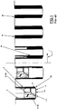
- a traditional method being used for carrying out the tightening mentioned above in a corresponding context is with reference to the pictorial shown in figure 1 such that first of all a basic hole is drilled into the ground, the diameter of the hole being significantly bigger than the earth pipe to be installed therein, whereafter, after the drilling, a separate earth pipe is installed in the hole. After this, the space between the earth pipe and the basic hole is filled with a tightening mass, such as e.g. injection sement or bentonite clay, simultaneously, when the protecting pipe with the big diameter that was used in the drilling, is pulled out from the hole possibly along with its drilling means.
- a tightening mass such as e.g. injection sement or bentonite clay
- a drilling head of a drilling unit existing inside a casing part that operates after the drilling as an earth pipe, in the drilling apparatus presented in this patent, is formed of a first frame part and an annular second frame part, the drilling surfaces of which are provided with drilling organs, such as drill bits or like, of the first and second drilling means or in other words of a center drill or a pilot and a reamer.
- the first frame part forming the the first drilling means is being released from the second frame part forming the reamer, in order to pull the same out from a drilled hole after the drilling situation together with the drill rods.
- the drilling can be performed reliably so that the groundwater is not allowed to get dirty by leading the tightening mass in the injection phase as an advantageous embodiment by flow channels in connection with the casing shoe with adequately large dimensioned flow cross sections outside the casing part that acts after the drilling of the basic hole as an earth pipe. Thanks to the invention, it is thus possible to minimize the amount of the tightening mass to be used and to remove e.g.
- the invention relates to a method for coupling an earth pipe into the ground when exploiting an apparatus that has a drilling device 1, consisting of a casing part 2 and a drilling unit 3 that exists at least during a drilling situation essentially inside thereof, which unit includes: first drilling means 4 at a drilling head thereof for drilling a center hole and second drilling means 5 for reaming the center hole for the casing part 2, whereby the essentially rotationally symmetrical first drilling means and the second drilling means 4, 5 are coupled mutually first of all in a power transmitting manner in order to carry out cooperation thereof at least during a drilling situation for a rotational motion w4, a feeding motion z4 and/or a hammering motion t4 and on the other hand removably in order to enable removal of the first drilling means from a drilled hole and, whereby the casing part 2 is arranged to be drawn into the hole to be drilled by the first and/or second drilling means; and advantageously a flushing flow arrangement 6 first of all to feed a flushing medium by first flush
- solidifying mass M such as injection cement, bentonite clay or like, is being led to the bottom of the basic hole in order to couple the earth pipe to be installed in the basic hole with the surrounding ground, such as rock, for tightening the earth pipe into the rock hole, for anchoring of the same in place and/or for the like purpose.
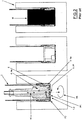
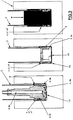
- the casing part 2 acting as an earth pipe is being coupled in the injection phase I into the ground according to the rightmost views of the pictorials in figures 3 and 6 by leading solidifying mass M, being brought internally in the casing part 2, by means of a flow-through assembly X essentially at a lower end of the casing part 2 and/or in front thereof, when viewed in the drilling direction s, into a space between an outer surface of the casing part 2 and the basic hole.
- the drilling head I of the drilling device's 1 drilling unit 3 is formed of a first frame part 4a and a second frame part 5a, wherein drilling surfaces P1, P2 of the frame parts are provided with drilling organs of the first and the second drilling means 4, 5, such as an integrated drilling part, separate drilling pieces, bits or like.
- the solidifying mass M is being led in the injection phase I from one or several flow-through channels X; X1/X2 belonging to the flow-through assembly essentially backwards with respect to the drilling direction s by a guide groove or grooves X1'/X2' essentially axially into an intermediate space surrounding the casing part 2.
- the invention relates also to an apparatus according to the description above and as shown in the appended drawings for coupling an earth pipe into the ground, in which a flow-through assembly X is arranged in the drilling device 1 essentially at a lower end of the casing part 2 and/or in front thereof, when viewed in the drilling direction s, in order to lead the solidifying mass M to be brought internally in the casing part 2 into a space between an outer surface of the casing part 2 and the basic hole e.g. according to the rightmost views in the pictorials of figures 4 and 6 .
- the drilling head I of the drilling device's 1 drilling unit 3 is formed of a first frame part 4a and a second frame part 5a, wherein drilling surfaces P1, P2 of the frame parts are provided with drilling organs of the first and the second drilling means 4, 5, such as an integrated drilling part, separate drilling pieces, bits or like.
- the radial flow-through channels have been arranged in connection with the casing shoe 8, but instead or in addition thereto it is also possible to arrange the radial flow-through of the tightening massa e.g. by perforations or nozzles etc. existing at the lower end of the casing part 2 (which have not, however, been presented in detail in the drawings).
- the flow-through assembly comprises a guide groove or grooves X1', X2' directed essentially backwards with respect to the drilling direction s from one or several essentially radial flow-through channels X; X1, X2, in order to lead the solidifying mass M essentially axially s into an intermediate space surrounding the casing part 2.
- a guide groove or grooves X1', X2' directed essentially backwards with respect to the drilling direction s from one or several essentially radial flow-through channels X; X1, X2, in order to lead the solidifying mass M essentially axially s into an intermediate space surrounding the casing part 2.
- the casing shoe can also be placed in an built-in manner at the end of the casing part etc.
Landscapes
- Life Sciences & Earth Sciences (AREA)
- Engineering & Computer Science (AREA)
- Geology (AREA)
- Mining & Mineral Resources (AREA)
- Physics & Mathematics (AREA)
- Environmental & Geological Engineering (AREA)
- Fluid Mechanics (AREA)
- General Life Sciences & Earth Sciences (AREA)
- Geochemistry & Mineralogy (AREA)
- Earth Drilling (AREA)
Claims (8)
- Procédé pour l'accouplement d'un tuyau de terre dans le sol lors de l'exploitation d'un appareil comportant un dispositif de forage (1) constitué d'une partie d'enveloppe (2) et d'une unité de forage (3) qui existe au moins au cours d'une situation de forage, une unité de forage, qui se trouve essentiellement à l'intérieur dudit dispositif, qui comprend : des premiers moyens de forage (4) à la tête de forage pour forer un trou central et des seconds moyens de forage (5) pour aléser le trou central pour l'enveloppe (2), grâce à quoi les premiers moyens de forage et des seconds moyens de forage (4, 5) sont caractérise sensiblement par une symétrie de rotation et couplés mutuellement avant tout d'une manière à transmettre d'énergie dans le but d'établir une coopération entre ceux-ci au moins lors d'une situation de forage pour un mouvement de rotation (w4), pour le mouvement d'avancement (z4) et / ou un mouvement de martelage (t4) et d'autre part de façon amovible pour permettre l'enlèvement des premiers moyens de forage d'un trou foré et, par lequel la partie d'enveloppe (2) est conçue de façon à être tirée à l'intérieur du trou devant être foré au moyen des premiers et/ou seconds moyens de forage ; et de préférence un ensemble d'écoulement de rinçage(6) d'abord pour alimenter un milieu de rinçage par des premiers moyens de rinçage (6a) pour le forage et d'autre part pour éliminer le milieu de rinçage et les résidus de forage générés par des seconds moyens de rinçage (6b) dans la partie d'enveloppe (2), par lequel après le perçage d'un trou de base pour le tuyau de terre et après le soulèvement des premiers moyens de forage (4), dans une phase d'injection suivante (I), la masse de solidification (M), telle qu'un ciment d'injection, une argile de bentonite ou similaire, est conduite au fond du trou de base afin de coupler le tuyau de terre, destiné à être installé dans le trou de base, avec le sol environnant, tel que la roche, pour serrer le tuyau de terre dans un trou de roche, pour l'ancrage de celle-ci en place et / ou pour un but similaire, caractérisé en ce que, après le forage du trou de base, la partie d'enveloppe (2) servant également de contact du tuyau de terre est couplée de la phase d'injection (I) dans le sol au moyen de la masse de solidification principale (M), amenée intérieurement dans la partie d'enveloppe (2), au moyen d'un ensemble en écoulement (X) essentiellement à une extrémité inférieure de la partie d'enveloppe (2) et / ou à l'avant de celui-ci, vu dans la (les) direction (s) de forage, dans un espace entre une surface extérieure de la partie d'enveloppe (2) et le trou de base pour effectuer une injection essentiellement du bas vers le haut.
- L'invention porte aussi sur un procédé tel que décrite dans la revendication 1 en exploitant un appareil dans lequel la tête de forage (I) de l'unité de forage (3) du dispositif de forage (1) est formée d'une première partie de bâti (4a) et d'une deuxième partie de bâti (5a), dans lesquelles les surfaces de forage (P1, P2) des parties de bâti sont munies d'organes de forage des premier et second moyens de forage (4, 5), tels qu'une partie de forage intégrée, des pièces de forage séparées, des parties ou similaires, caractérisé en ce que, lors de l'utilisation d'une unité de forage (3), au moyen de qui la partie d'enveloppe (2) est conçue de façon à être tirée à l'intérieur du trou devant être foré au moyen d'un sabot d'enveloppe (8) sous l'influence de l'électricité étant transmise par le second moyen de forage (5), la masse de solidification (M) est amenée de l'intérieur de la partie d'enveloppe (2) à l'extérieur par un ou plusieurs canaux d'écoulement essentiellement radiaux (X ; X1) à un bord arrière d'un sabot d'enveloppe (8).
- L'invention porte aussi sur un procédé tel que décrit dans la revendication 1, caractérisé en ce que, lors de l'utilisation d'une unité de forage (3), au moyen de qui la partie d'enveloppe (2) est conçue de façon à être tirée à l'intérieur du trou devant être foré au moyen d'un sabot d'enveloppe (8) sous l'influence de l'électricité étant transmise par le premier moyen de forage (4), la masse de solidification (M) est amenée de l'intérieur de la partie d'enveloppe (2) à l'extérieur par un ou plusieurs canaux d'écoulement essentiellement radiaux (X ; X1) à un bord avant de la partie d'enveloppe (8).
- Les inventions portent aussi sur un procédé tel que décrit dans les revendications précédentes 1-3, caractérisé en ce que la masse de solidification (M) est amenée dans la phase d'injection (I) à partir d'un ou de plusieurs canaux d'écoulement (X ; X1 / X2) faisant partie d'un ensemble en écoulement de manière inversée par rapport à la (aux) direction (s) de forage par une ou plusieurs rainures de guidage (X1 '/ X2') sensiblement axialement dans un espace intermédiaire entourant la partie d'enveloppe (2).
- L'appareil pour l'accouplement d'un tuyau de terre dans le sol comportant un dispositif de forage (1) constitué d'une partie d'enveloppe (2) et d'une unité de forage (3) qui existe au moins au cours d'une situation de forage, une unité de forage, qui se trouve essentiellement à l'intérieur dudit dispositif, qui comprend : des premiers moyens de forage (4) à la tête de forage pour forer un trou central et des seconds moyens de forage (5) pour aléser le trou central pour l'enveloppe (2), grâce à quoi les premiers moyens de forage et des seconds moyens de forage (4, 5) sont caractérisés sensiblement par une symétrie de rotation et couplés mutuellement avant tout d'une manière à transmettre d'énergie dans le but d'établir une coopération entre ceux-ci au moins lors d'une situation de forage pour un mouvement de rotation (w4), pour le mouvement d'avancement (z4) et / ou un mouvement de martelage (t4) et d'autre part de façon amovible pour permettre l'enlèvement des premiers moyens de forage d'un trou foré et, par lequel la partie d'enveloppe (2) est conçue de façon à être tirée à l'intérieur du trou devant être foré au moyen des premiers et/ou seconds moyens de forage ; et de préférence un ensemble d'écoulement de rinçage(6) d'abord pour alimenter un milieu de rinçage par des premiers moyens de rinçage (6a) pour le forage et d'autre part pour éliminer le milieu de rinçage et les résidus de forage générés par des seconds moyens de rinçage (6b) dans la partie d'enveloppe (2), par lequel un tuyau de terre est conduit au fond du trou de base devant être foré pour celui-ci est conçue de façon à être couplé au sol environnant, tel qu'une roche pour serrer le tuyau de terre dans un trou de roche, pour l'ancrage de celle-ci en place et / ou pour un but similaire, par lequel après le perçage d'un trou de base pour le tuyau de terre et après le soulèvement des premiers moyens de forage (4), la masse de solidification (M), telle qu'un ciment d'injection, une argile de bentonite ou similaire, est conduite au fond du trou de base caractérisé en ce que, un ensemble en écoulement (X) est mis dans le dispositif de forage (1) essentiellement à une extrémité inférieure de la partie d'enveloppe (2) et / ou devant celle-ci, vue dans la (les) direction (s) de forage, afin d'amener la masse de solidification (M) à être amenée intérieurement dans la partie d'enveloppe (2) dans un espace entre une surface extérieure de la partie d'enveloppe (2) et le trou de base pour effectuer une injection essentiellement du bas vers le haut.
- L'appareil porte aussi sur un procédé tel que décrit dans la revendication 5 dans lequel la tête de forage (I) de l'unité de forage (3) du dispositif de forage (1) est formée d'une première partie de bâti (4a) et d'une deuxième partie de bâti (5a), dans lesquelles les surfaces de forage (P1, P2) des parties de bâti sont munies d'organes de forage des premier et second moyens de forage (4, 5), tels qu'une partie de forage intégrée, des pièces de forage séparées, des parties ou similaires, caractérisé en ce que, lors la partie d'enveloppe (2) est conçue de façon à être tirée à l'intérieur du trou devant être forée au moyen d'un sabot d'enveloppe (8) sous l'influence de l'électricité étant transmise par le second moyen de forage (5), essentiellement à l'arrière du sabot d'enveloppe (8) est disposé par un ou plusieurs canaux d'écoulement essentiellement radiaux (X ; X1) pour amener la masse de solidification (M) de l'intérieur de la partie d'enveloppe (2) à l'extérieur de celle-ci.
- L'appareil porte aussi sur un procédé tel que décrit dans la revendication 5, caractérisé en ce que, lors de la partie d'enveloppe (2) est conçue de façon à être tirée à l'intérieur du trou devant être foré au moyen d'un sabot d'enveloppe (8) sous l'influence de l'électricité étant transmise par le premier moyen de forage (4), essentiellement à l'avant du sabot d'enveloppe (8) est disposé par un ou plusieurs canaux d'écoulement essentiellement radiaux (X ; X2) pour amener la masse de solidification (M) de l'intérieur de la partie d'enveloppe (2) à l'extérieur de celle-ci.
- L'appareil porte aussi sur un procédé tel que décrit dans les revendications précédentes 5-7, caractérisé en ce qu'un ensemble en écoulement comprend une ou plusieurs rainures de guidage (X1 '/ X2') de manière inversée par rapport à la (aux) direction (s) de forage à partir d'un ou plusieurs canaux d'écoulement essentiellement radiaux (X ; X1, X2) afin d'amener la masse de solidification (M) sensiblement axialement dans un espace intermédiaire entourant la partie d'enveloppe (2).
Applications Claiming Priority (2)
| Application Number | Priority Date | Filing Date | Title |
|---|---|---|---|
| FI20106154A FI20106154A0 (fi) | 2010-11-03 | 2010-11-03 | Menetelmä ja laitteisto maaputken kytkemiseksi maaperään |
| PCT/FI2011/050957 WO2012059641A1 (fr) | 2010-11-03 | 2011-11-01 | Procédé et appareil pour l'accouplement d'un tuyau de terre dans le sol au moyen d'une masse de solidification |
Publications (3)
| Publication Number | Publication Date |
|---|---|
| EP2635768A1 EP2635768A1 (fr) | 2013-09-11 |
| EP2635768A4 EP2635768A4 (fr) | 2017-08-23 |
| EP2635768B1 true EP2635768B1 (fr) | 2018-03-21 |
Family
ID=43268935
Family Applications (1)
| Application Number | Title | Priority Date | Filing Date |
|---|---|---|---|
| EP11837633.4A Active EP2635768B1 (fr) | 2010-11-03 | 2011-11-01 | Procédé et appareil pour l'accouplement d'un tuyau de terre dans le sol au moyen d'une masse de solidification |
Country Status (4)
| Country | Link |
|---|---|
| US (1) | US9175519B2 (fr) |
| EP (1) | EP2635768B1 (fr) |
| FI (1) | FI20106154A0 (fr) |
| WO (1) | WO2012059641A1 (fr) |
Families Citing this family (1)
| Publication number | Priority date | Publication date | Assignee | Title |
|---|---|---|---|---|
| FI125230B (fi) * | 2013-04-19 | 2015-07-31 | Sotkamon Porakaivo Oy | Menetelmä ja laitteisto kallioon porattujen porapaalujen ulkopuolisen injektoinnin suorittamiseksi |
Family Cites Families (9)
| Publication number | Priority date | Publication date | Assignee | Title |
|---|---|---|---|---|
| GB2170528A (en) * | 1985-01-26 | 1986-08-06 | Ed Oscar Seabourn | Casing extender |
| US5351759A (en) * | 1992-10-22 | 1994-10-04 | Shell Oil Company | Slag-cement displacement by direct fluid contact |
| FI95618C (fi) * | 1992-12-03 | 1998-09-03 | Jorma Jaervelae | Porauslaitteisto |
| US5472057A (en) * | 1994-04-11 | 1995-12-05 | Atlantic Richfield Company | Drilling with casing and retrievable bit-motor assembly |
| US7334650B2 (en) * | 2000-04-13 | 2008-02-26 | Weatherford/Lamb, Inc. | Apparatus and methods for drilling a wellbore using casing |
| US6554070B2 (en) | 2001-03-16 | 2003-04-29 | Intevep, S.A. | Composition and method for sealing an annular space between a well bore and a casing |
| FI20086206A0 (fi) * | 2008-12-17 | 2008-12-17 | Atlas Copco Rotex Ab Oy | Menetelmä ja laitteisto uppoporaukseen |
| US20100252331A1 (en) | 2009-04-01 | 2010-10-07 | High Angela D | Methods for forming boring shoes for wellbore casing, and boring shoes and intermediate structures formed by such methods |
| US8186457B2 (en) * | 2009-09-17 | 2012-05-29 | Tesco Corporation | Offshore casing drilling method |
-
2010
- 2010-11-03 FI FI20106154A patent/FI20106154A0/fi not_active Application Discontinuation
-
2011
- 2011-11-01 WO PCT/FI2011/050957 patent/WO2012059641A1/fr not_active Ceased
- 2011-11-01 US US13/885,882 patent/US9175519B2/en not_active Expired - Fee Related
- 2011-11-01 EP EP11837633.4A patent/EP2635768B1/fr active Active
Non-Patent Citations (1)
| Title |
|---|
| None * |
Also Published As
| Publication number | Publication date |
|---|---|
| US9175519B2 (en) | 2015-11-03 |
| EP2635768A1 (fr) | 2013-09-11 |
| FI20106154A0 (fi) | 2010-11-03 |
| US20130284515A1 (en) | 2013-10-31 |
| EP2635768A4 (fr) | 2017-08-23 |
| WO2012059641A1 (fr) | 2012-05-10 |
Similar Documents
| Publication | Publication Date | Title |
|---|---|---|
| JP5629271B2 (ja) | ダウンザホール穿孔のための方法および装置 | |
| EP1373675B1 (fr) | Procede de forage et appareil de forage | |
| CN1062635C (zh) | 在土中钻孔的方法、钻头组件和内钻头 | |
| RU2468177C2 (ru) | Буровое долото для ударно-поворотного бурения горной породы и способ его изготовления | |
| US20110198129A1 (en) | Method and drilling apparatus for down-the-hole drilling | |
| NO20050124L (no) | Fremgangsmate og innretning med integrert eller pa annen mate kombinert foring ut av en bronnboring og oppkverning av en seksjon for sideveis boring eller avviksboring | |
| EP3060742B1 (fr) | Dispositif de forage | |
| KR20160099530A (ko) | 드릴 장치 | |
| EP2635768B1 (fr) | Procédé et appareil pour l'accouplement d'un tuyau de terre dans le sol au moyen d'une masse de solidification | |
| EP2370660B1 (fr) | Procédé et appareil de forage en fond de trou | |
| PL196595B1 (pl) | Przyrząd do wiercenia otworów wiertniczych, w szczególności do wiercenia udarowego lub udarowo-obrotowego | |
| AU1326300A (en) | Method and device in down-the-hole drilling | |
| US9611701B2 (en) | Method and apparatus for plastic pipe drilling | |
| JP3834679B2 (ja) | ノンコア削孔装置及びノンコア削孔コア採取工法 | |
| EP2675982B1 (fr) | Procédé et appareil de forage en fond de trou | |
| CA2956424C (fr) | Procede pour assembler un appareil de forage de fond-de-trou pour un forage par tuyau en matiere plastique et appareil de forage de fond-de-trou | |
| KR100990335B1 (ko) | 지반천공장치 | |
| JPH0743264Y2 (ja) | ボーリングロッド | |
| US7389829B2 (en) | Method and apparatus for forming bored hole | |
| WO2009156569A1 (fr) | Procédé et appareil de forage | |
| WO2017089647A1 (fr) | Procédé de forage de fond et dispositif de forage de fond | |
| WO2012038583A1 (fr) | Procédé et appareil pour forage de fond de trou | |
| KR20090012431U (ko) | 지하 천공기용 비트 | |
| JP2000352290A (ja) | 掘削ビット及びアンカー工法 | |
| HK1189925B (en) | Method and apparatus for down-the-hole drilling |
Legal Events
| Date | Code | Title | Description |
|---|---|---|---|
| PUAI | Public reference made under article 153(3) epc to a published international application that has entered the european phase |
Free format text: ORIGINAL CODE: 0009012 |
|
| 17P | Request for examination filed |
Effective date: 20130521 |
|
| AK | Designated contracting states |
Kind code of ref document: A1 Designated state(s): AL AT BE BG CH CY CZ DE DK EE ES FI FR GB GR HR HU IE IS IT LI LT LU LV MC MK MT NL NO PL PT RO RS SE SI SK SM TR |
|
| DAX | Request for extension of the european patent (deleted) | ||
| RA4 | Supplementary search report drawn up and despatched (corrected) |
Effective date: 20170720 |
|
| RIC1 | Information provided on ipc code assigned before grant |
Ipc: E21B 33/14 20060101AFI20170714BHEP Ipc: E21B 7/20 20060101ALI20170714BHEP |
|
| GRAP | Despatch of communication of intention to grant a patent |
Free format text: ORIGINAL CODE: EPIDOSNIGR1 |
|
| INTG | Intention to grant announced |
Effective date: 20171017 |
|
| GRAJ | Information related to disapproval of communication of intention to grant by the applicant or resumption of examination proceedings by the epo deleted |
Free format text: ORIGINAL CODE: EPIDOSDIGR1 |
|
| GRAS | Grant fee paid |
Free format text: ORIGINAL CODE: EPIDOSNIGR3 |
|
| GRAP | Despatch of communication of intention to grant a patent |
Free format text: ORIGINAL CODE: EPIDOSNIGR1 |
|
| RAP1 | Party data changed (applicant data changed or rights of an application transferred) |
Owner name: OY EPIROC DRILLING TOOLS AB |
|
| GRAA | (expected) grant |
Free format text: ORIGINAL CODE: 0009210 |
|
| INTC | Intention to grant announced (deleted) | ||
| INTG | Intention to grant announced |
Effective date: 20180208 |
|
| AK | Designated contracting states |
Kind code of ref document: B1 Designated state(s): AL AT BE BG CH CY CZ DE DK EE ES FI FR GB GR HR HU IE IS IT LI LT LU LV MC MK MT NL NO PL PT RO RS SE SI SK SM TR |
|
| REG | Reference to a national code |
Ref country code: GB Ref legal event code: FG4D |
|
| REG | Reference to a national code |
Ref country code: CH Ref legal event code: EP |
|
| REG | Reference to a national code |
Ref country code: AT Ref legal event code: REF Ref document number: 981321 Country of ref document: AT Kind code of ref document: T Effective date: 20180415 |
|
| REG | Reference to a national code |
Ref country code: IE Ref legal event code: FG4D |
|
| REG | Reference to a national code |
Ref country code: DE Ref legal event code: R096 Ref document number: 602011046803 Country of ref document: DE |
|
| REG | Reference to a national code |
Ref country code: SE Ref legal event code: TRGR |
|
| REG | Reference to a national code |
Ref country code: NL Ref legal event code: MP Effective date: 20180321 |
|
| PG25 | Lapsed in a contracting state [announced via postgrant information from national office to epo] |
Ref country code: LT Free format text: LAPSE BECAUSE OF FAILURE TO SUBMIT A TRANSLATION OF THE DESCRIPTION OR TO PAY THE FEE WITHIN THE PRESCRIBED TIME-LIMIT Effective date: 20180321 Ref country code: CY Free format text: LAPSE BECAUSE OF FAILURE TO SUBMIT A TRANSLATION OF THE DESCRIPTION OR TO PAY THE FEE WITHIN THE PRESCRIBED TIME-LIMIT Effective date: 20180321 Ref country code: HR Free format text: LAPSE BECAUSE OF FAILURE TO SUBMIT A TRANSLATION OF THE DESCRIPTION OR TO PAY THE FEE WITHIN THE PRESCRIBED TIME-LIMIT Effective date: 20180321 |
|
| REG | Reference to a national code |
Ref country code: LT Ref legal event code: MG4D |
|
| REG | Reference to a national code |
Ref country code: AT Ref legal event code: MK05 Ref document number: 981321 Country of ref document: AT Kind code of ref document: T Effective date: 20180321 |
|
| REG | Reference to a national code |
Ref country code: NO Ref legal event code: T2 Effective date: 20180321 |
|
| PG25 | Lapsed in a contracting state [announced via postgrant information from national office to epo] |
Ref country code: RS Free format text: LAPSE BECAUSE OF FAILURE TO SUBMIT A TRANSLATION OF THE DESCRIPTION OR TO PAY THE FEE WITHIN THE PRESCRIBED TIME-LIMIT Effective date: 20180321 Ref country code: BG Free format text: LAPSE BECAUSE OF FAILURE TO SUBMIT A TRANSLATION OF THE DESCRIPTION OR TO PAY THE FEE WITHIN THE PRESCRIBED TIME-LIMIT Effective date: 20180621 Ref country code: GR Free format text: LAPSE BECAUSE OF FAILURE TO SUBMIT A TRANSLATION OF THE DESCRIPTION OR TO PAY THE FEE WITHIN THE PRESCRIBED TIME-LIMIT Effective date: 20180622 Ref country code: LV Free format text: LAPSE BECAUSE OF FAILURE TO SUBMIT A TRANSLATION OF THE DESCRIPTION OR TO PAY THE FEE WITHIN THE PRESCRIBED TIME-LIMIT Effective date: 20180321 |
|
| PG25 | Lapsed in a contracting state [announced via postgrant information from national office to epo] |
Ref country code: RO Free format text: LAPSE BECAUSE OF FAILURE TO SUBMIT A TRANSLATION OF THE DESCRIPTION OR TO PAY THE FEE WITHIN THE PRESCRIBED TIME-LIMIT Effective date: 20180321 Ref country code: PL Free format text: LAPSE BECAUSE OF FAILURE TO SUBMIT A TRANSLATION OF THE DESCRIPTION OR TO PAY THE FEE WITHIN THE PRESCRIBED TIME-LIMIT Effective date: 20180321 Ref country code: ES Free format text: LAPSE BECAUSE OF FAILURE TO SUBMIT A TRANSLATION OF THE DESCRIPTION OR TO PAY THE FEE WITHIN THE PRESCRIBED TIME-LIMIT Effective date: 20180321 Ref country code: AL Free format text: LAPSE BECAUSE OF FAILURE TO SUBMIT A TRANSLATION OF THE DESCRIPTION OR TO PAY THE FEE WITHIN THE PRESCRIBED TIME-LIMIT Effective date: 20180321 Ref country code: NL Free format text: LAPSE BECAUSE OF FAILURE TO SUBMIT A TRANSLATION OF THE DESCRIPTION OR TO PAY THE FEE WITHIN THE PRESCRIBED TIME-LIMIT Effective date: 20180321 Ref country code: EE Free format text: LAPSE BECAUSE OF FAILURE TO SUBMIT A TRANSLATION OF THE DESCRIPTION OR TO PAY THE FEE WITHIN THE PRESCRIBED TIME-LIMIT Effective date: 20180321 |
|
| PG25 | Lapsed in a contracting state [announced via postgrant information from national office to epo] |
Ref country code: SM Free format text: LAPSE BECAUSE OF FAILURE TO SUBMIT A TRANSLATION OF THE DESCRIPTION OR TO PAY THE FEE WITHIN THE PRESCRIBED TIME-LIMIT Effective date: 20180321 Ref country code: AT Free format text: LAPSE BECAUSE OF FAILURE TO SUBMIT A TRANSLATION OF THE DESCRIPTION OR TO PAY THE FEE WITHIN THE PRESCRIBED TIME-LIMIT Effective date: 20180321 Ref country code: SK Free format text: LAPSE BECAUSE OF FAILURE TO SUBMIT A TRANSLATION OF THE DESCRIPTION OR TO PAY THE FEE WITHIN THE PRESCRIBED TIME-LIMIT Effective date: 20180321 Ref country code: CZ Free format text: LAPSE BECAUSE OF FAILURE TO SUBMIT A TRANSLATION OF THE DESCRIPTION OR TO PAY THE FEE WITHIN THE PRESCRIBED TIME-LIMIT Effective date: 20180321 |
|
| PG25 | Lapsed in a contracting state [announced via postgrant information from national office to epo] |
Ref country code: PT Free format text: LAPSE BECAUSE OF FAILURE TO SUBMIT A TRANSLATION OF THE DESCRIPTION OR TO PAY THE FEE WITHIN THE PRESCRIBED TIME-LIMIT Effective date: 20180723 |
|
| REG | Reference to a national code |
Ref country code: DE Ref legal event code: R097 Ref document number: 602011046803 Country of ref document: DE |
|
| PLBE | No opposition filed within time limit |
Free format text: ORIGINAL CODE: 0009261 |
|
| STAA | Information on the status of an ep patent application or granted ep patent |
Free format text: STATUS: NO OPPOSITION FILED WITHIN TIME LIMIT |
|
| PG25 | Lapsed in a contracting state [announced via postgrant information from national office to epo] |
Ref country code: DK Free format text: LAPSE BECAUSE OF FAILURE TO SUBMIT A TRANSLATION OF THE DESCRIPTION OR TO PAY THE FEE WITHIN THE PRESCRIBED TIME-LIMIT Effective date: 20180321 |
|
| 26N | No opposition filed |
Effective date: 20190102 |
|
| PG25 | Lapsed in a contracting state [announced via postgrant information from national office to epo] |
Ref country code: SI Free format text: LAPSE BECAUSE OF FAILURE TO SUBMIT A TRANSLATION OF THE DESCRIPTION OR TO PAY THE FEE WITHIN THE PRESCRIBED TIME-LIMIT Effective date: 20180321 |
|
| REG | Reference to a national code |
Ref country code: CH Ref legal event code: PL |
|
| PG25 | Lapsed in a contracting state [announced via postgrant information from national office to epo] |
Ref country code: MC Free format text: LAPSE BECAUSE OF FAILURE TO SUBMIT A TRANSLATION OF THE DESCRIPTION OR TO PAY THE FEE WITHIN THE PRESCRIBED TIME-LIMIT Effective date: 20180321 Ref country code: LU Free format text: LAPSE BECAUSE OF NON-PAYMENT OF DUE FEES Effective date: 20181101 |
|
| REG | Reference to a national code |
Ref country code: BE Ref legal event code: MM Effective date: 20181130 |
|
| REG | Reference to a national code |
Ref country code: IE Ref legal event code: MM4A |
|
| PG25 | Lapsed in a contracting state [announced via postgrant information from national office to epo] |
Ref country code: LI Free format text: LAPSE BECAUSE OF NON-PAYMENT OF DUE FEES Effective date: 20181130 Ref country code: CH Free format text: LAPSE BECAUSE OF NON-PAYMENT OF DUE FEES Effective date: 20181130 |
|
| PG25 | Lapsed in a contracting state [announced via postgrant information from national office to epo] |
Ref country code: FR Free format text: LAPSE BECAUSE OF NON-PAYMENT OF DUE FEES Effective date: 20181130 Ref country code: IE Free format text: LAPSE BECAUSE OF NON-PAYMENT OF DUE FEES Effective date: 20181101 |
|
| PG25 | Lapsed in a contracting state [announced via postgrant information from national office to epo] |
Ref country code: BE Free format text: LAPSE BECAUSE OF NON-PAYMENT OF DUE FEES Effective date: 20181130 |
|
| PG25 | Lapsed in a contracting state [announced via postgrant information from national office to epo] |
Ref country code: MT Free format text: LAPSE BECAUSE OF NON-PAYMENT OF DUE FEES Effective date: 20181101 |
|
| REG | Reference to a national code |
Ref country code: NO Ref legal event code: CHAD Owner name: TERRAROC FINLAND OY, FI Ref country code: FI Ref legal event code: PCE Owner name: TERRAROC FINLAND OY |
|
| REG | Reference to a national code |
Ref country code: DE Ref legal event code: R082 Ref document number: 602011046803 Country of ref document: DE Representative=s name: PUSCHMANN BORCHERT BARDEHLE PATENTANWAELTE PAR, DE Ref country code: DE Ref legal event code: R081 Ref document number: 602011046803 Country of ref document: DE Owner name: TERRAROC FINLAND OY, FI Free format text: FORMER OWNER: OY EPIROC DRILLING TOOLS AB, TAMPERE, FI Ref country code: DE Ref legal event code: R082 Ref document number: 602011046803 Country of ref document: DE Representative=s name: PUSCHMANN BORCHERT KAISER KLETTNER PATENTANWAE, DE |
|
| PG25 | Lapsed in a contracting state [announced via postgrant information from national office to epo] |
Ref country code: HU Free format text: LAPSE BECAUSE OF FAILURE TO SUBMIT A TRANSLATION OF THE DESCRIPTION OR TO PAY THE FEE WITHIN THE PRESCRIBED TIME-LIMIT; INVALID AB INITIO Effective date: 20111101 Ref country code: MK Free format text: LAPSE BECAUSE OF NON-PAYMENT OF DUE FEES Effective date: 20180321 |
|
| PG25 | Lapsed in a contracting state [announced via postgrant information from national office to epo] |
Ref country code: IS Free format text: LAPSE BECAUSE OF FAILURE TO SUBMIT A TRANSLATION OF THE DESCRIPTION OR TO PAY THE FEE WITHIN THE PRESCRIBED TIME-LIMIT Effective date: 20180721 |
|
| PGFP | Annual fee paid to national office [announced via postgrant information from national office to epo] |
Ref country code: TR Payment date: 20221028 Year of fee payment: 12 Ref country code: SE Payment date: 20221127 Year of fee payment: 12 Ref country code: NO Payment date: 20221125 Year of fee payment: 12 Ref country code: IT Payment date: 20221123 Year of fee payment: 12 Ref country code: GB Payment date: 20221128 Year of fee payment: 12 Ref country code: FI Payment date: 20221125 Year of fee payment: 12 Ref country code: DE Payment date: 20221125 Year of fee payment: 12 |
|
| REG | Reference to a national code |
Ref country code: DE Ref legal event code: R119 Ref document number: 602011046803 Country of ref document: DE |
|
| REG | Reference to a national code |
Ref country code: SE Ref legal event code: EUG |
|
| GBPC | Gb: european patent ceased through non-payment of renewal fee |
Effective date: 20231101 |
|
| PG25 | Lapsed in a contracting state [announced via postgrant information from national office to epo] |
Ref country code: NO Free format text: LAPSE BECAUSE OF NON-PAYMENT OF DUE FEES Effective date: 20231130 Ref country code: FI Free format text: LAPSE BECAUSE OF NON-PAYMENT OF DUE FEES Effective date: 20231101 |
|
| PG25 | Lapsed in a contracting state [announced via postgrant information from national office to epo] |
Ref country code: SE Free format text: LAPSE BECAUSE OF NON-PAYMENT OF DUE FEES Effective date: 20231102 |
|
| PG25 | Lapsed in a contracting state [announced via postgrant information from national office to epo] |
Ref country code: DE Free format text: LAPSE BECAUSE OF NON-PAYMENT OF DUE FEES Effective date: 20240601 |
|
| PG25 | Lapsed in a contracting state [announced via postgrant information from national office to epo] |
Ref country code: GB Free format text: LAPSE BECAUSE OF NON-PAYMENT OF DUE FEES Effective date: 20231101 |
|
| PG25 | Lapsed in a contracting state [announced via postgrant information from national office to epo] |
Ref country code: GB Free format text: LAPSE BECAUSE OF NON-PAYMENT OF DUE FEES Effective date: 20231101 Ref country code: DE Free format text: LAPSE BECAUSE OF NON-PAYMENT OF DUE FEES Effective date: 20240601 |
|
| PG25 | Lapsed in a contracting state [announced via postgrant information from national office to epo] |
Ref country code: IT Free format text: LAPSE BECAUSE OF NON-PAYMENT OF DUE FEES Effective date: 20231101 |
|
| PG25 | Lapsed in a contracting state [announced via postgrant information from national office to epo] |
Ref country code: IT Free format text: LAPSE BECAUSE OF NON-PAYMENT OF DUE FEES Effective date: 20231101 |