EP2636128B1 - Elektromotor, bausatz und verfahren zur herstellung - Google Patents
Elektromotor, bausatz und verfahren zur herstellung Download PDFInfo
- Publication number
- EP2636128B1 EP2636128B1 EP11760706.9A EP11760706A EP2636128B1 EP 2636128 B1 EP2636128 B1 EP 2636128B1 EP 11760706 A EP11760706 A EP 11760706A EP 2636128 B1 EP2636128 B1 EP 2636128B1
- Authority
- EP
- European Patent Office
- Prior art keywords
- housing part
- deflecting
- electric motor
- screw
- flange
- Prior art date
- Legal status (The legal status is an assumption and is not a legal conclusion. Google has not performed a legal analysis and makes no representation as to the accuracy of the status listed.)
- Active
Links
Images


Classifications
-
- H—ELECTRICITY
- H02—GENERATION; CONVERSION OR DISTRIBUTION OF ELECTRIC POWER
- H02K—DYNAMO-ELECTRIC MACHINES
- H02K5/00—Casings; Enclosures; Supports
- H02K5/04—Casings or enclosures characterised by the shape, form or construction thereof
- H02K5/15—Mounting arrangements for bearing-shields or end plates
-
- H—ELECTRICITY
- H02—GENERATION; CONVERSION OR DISTRIBUTION OF ELECTRIC POWER
- H02K—DYNAMO-ELECTRIC MACHINES
- H02K5/00—Casings; Enclosures; Supports
- H02K5/04—Casings or enclosures characterised by the shape, form or construction thereof
- H02K5/20—Casings or enclosures characterised by the shape, form or construction thereof with channels or ducts for flow of cooling medium
- H02K5/203—Casings or enclosures characterised by the shape, form or construction thereof with channels or ducts for flow of cooling medium specially adapted for liquids, e.g. cooling jackets
Definitions
- the invention relates to an electric motor, a kit and a method for manufacturing.
- the invention is therefore based on the object to enable a cost-effective production of motors.
- the object is achieved in the electric motor according to the in claim 1, in the kit according to the in claim 13 and in the method for manufacturing according to the features indicated in claim 15.
- the electric motor has a housing part which accommodates the laminated stator core, in particular a housing part which frictionally receives the stator laminated core, wherein a flange part receives a first bearing for supporting the rotor shaft, wherein a deflecting part is arranged between the flange part and the housing part, wherein a screw connection between the flange part and deflecting part is provided, which comprises a threaded part, wherein a screw connection between deflecting part and housing part is provided.
- the advantage here is that is made possible by the two screw that the flange is connectable with a similar screw to another type of housing part and thus in a simple way another engine can be produced.
- an interface to the flange part can be generated within a series, which remains the same within the series in all variants, ie electric motors.
- housing parts with different functionalities can be connected to the flange part.
- the flange part is connected to a first axial, that is to say in the motor axis direction, end region of the deflection part.
- a screw is provided in the screw connection between the flange part and the deflecting part, in particular with its screw head or screwed onto the screw thread of the screw nut, and is screwed into the threaded part, in particular into an internal thread of the threaded part, and the threaded part is screwed into the deflecting part.
- a screw is provided in the screw connection between deflecting part and housing part, which contacts the deflecting part, in particular with its screw head, and is screwed into the housing part.
- the screw of the screw connection between deflecting part and housing part is screwed into a thread which is cut into the inner wall of a recess which is axially continuous through the housing part.
- the housing part is a continuous casting, in particular a reworked continuous casting.
- the advantage here is that a particularly simple and inexpensive production is possible.
- a seal between deflecting part and housing part is arranged, in particular a flat gasket.
- the threaded portion is a threaded bush having an internal thread and an external thread.
- the threaded bush is tightened by a hexagon socket.
- the housing part has cooling channels, in particular a plurality of cooling channels running continuously in the axial direction.
- the advantage here is that an effective cooling is available adjustable.
- the deflection part has deflection regions, inlet region and / or outlet region for the cooling medium, in particular wherein a connection device for introducing or removing cooling medium is arranged on the deflecting part.
- a connection device for introducing or removing cooling medium is arranged on the deflecting part.
- the threaded part touches the flange, in particular wherein a screw head or a nut touches the threaded portion.
- a support of the threaded part on the flange in the axial direction is executable.
- a rotor shaft bearing Lageres receiving flange is connected via a corresponding screw with threaded portion with another deflector which is disposed between the other flange and the housing part and is connected by means of a screw connection to the housing part.
- all recesses are axially continuous and it is a deflection made as a continuous casting.
- a seal in particular a flat gasket, is arranged between each deflecting part and the respective flange part connected by means of a screw connection.
- the first electric motor has a housing part accommodating the laminated stator core
- the second electric motor has a stator core accommodating the housing part, which has cooling channels
- the first electric motor has a housing part, to which a flange part is screw-connected, which has a bearing for supporting the rotor shaft of the second electric motor, wherein a screwed into the housing part screw touches the flange, in particular and presses against the housing part
- the second electric motor has an identical, in particular identical, flange part and a same, in particular identical, screw, which contacts the flange part, and is screwed into a threaded part, which is screwed into a deflection part, which is connected to a housing part of the second electric motor, in particular, wherein the axial length of the housing part of the first motor is equal to the axial length having the unit, in particular stator housing part, which is formed from the housing part of the second motor and the deflection parts screw
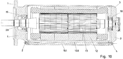
- a flange 1 is provided, which also in the engine variant according to FIG. 10 , So without cooling by a cooling medium, is provided.
- the kit includes a stator to FIG. 5 , which is composed of a housing part 10 and the deflecting parts 7 and 15, and an in FIG. 10 apparent stator.
- the kit comprises an A-side and a B-side flange part (1, 3) and associated connecting means,
- FIG. 1 is permanent magnets 13 are arranged on a rotor shaft 20 and thus the motor designed as a synchronous motor.
- a short-circuit cage can be provided on the rotor shaft for execution as an asynchronous motor or LSPM motor.
- the rotor shaft 20 is mounted by means of the bearing 19 in the flange part 1 and mounted by means of the bearing 18 in the flange part 3.
- the laminated stator core 12 is exemplarily stanzpiert and frictionally inserted in the housing part 10.
- Statorblechp 12 the stator winding is added. The deflection of the stator winding protrude into the axial regions, which are also covered by the deflecting parts (7, 15).
- a connecting screw 2, in particular as in FIG. 2 is shown, is passed through a bore of the flange 1 and into an internal thread 21 of a threaded bushing. 6 screwed, the external thread 22 is screwed into a threaded bore of the deflecting 7.
- this has a stepped bore, so that the threaded bushing can be received in that region of the stepped bore which has a larger inner diameter.
- a connecting screw 8 is guided, wherein the screw head is arranged in the region of greater inner diameter of the stepped bore and has a larger diameter than the inner diameter in the region of the stepped bore with smaller inner diameter.
- the screw 8 is screwed me its thread into a threaded bore of the housing part 10.
- the threaded hole is in this case introduced into a recess 11, which is axially elongated, since the housing part 10 is made as a continuous casting, in particular aluminum extruded casting, and thus the recess 11 is continuous in the axial direction.
- a corresponding interface is created by the flange 3 is screwed by means of the connecting screw 4 in a threaded bushing 16 and this in turn is screwed with its external thread in the region with a larger inner diameter of a stepped bore in the deflection member 15.
- a connecting screw 14 is provided, with which the deflecting member 15 is screwed to the housing part 10 to form a stator housing part.
- the connecting screw 14 is screwed into a thread, which is designed to be continuous in the recess 11 of the housing part 10.
- the screw head of the connecting screw 14 likewise has a larger diameter than the inner diameter of that region of the stepped bore which has a smaller diameter, that is to say is provided in the smaller diameter step region.
- the cooling medium 9 in a deflection region of the deflection part 7 is in FIG. 1 indicated.
- a seal 23 is provided in each case, which is preferably designed as a flat gasket.
- FIG. 3 the deflection member 15 is shown in more detail, wherein the bores 31 are shown in more detail for receiving the threaded bushing 16.
- deflection regions 30 are shown, into each of which incoming and outgoing cooling channels open.
- the cooling medium passes into a first inlet region from which a wide cooling channel 41 and a narrow circular cooling channel 42 go out.
- a wide cooling channel 41 and a narrow circular cooling channel 42 go out.
- these channels in turn lead into a deflection region 46, from which in turn a wide cooling channel 47 and a narrow cooling channel lead out and are deflected over a deflection region at the other axial end.
- the cooling channels are executed in the Beriech of the housing part 10, which is designed as a continuous casting, consistently.
- the cooling medium is guided meandering in the axial direction and circumferential direction, wherein it is guided back and forth in the axial direction.
- deflection areas 49 and 50 are deflection areas 49 and 50.
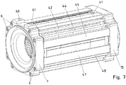
- connection areas (60, 61) for outlet and inlet of the cooling medium at the deflecting part 7 are in FIG. 6 shown.
- FIG. 8 the housing part is shown with stator, wherein it is manufactured as a continuous casting profile and is post-processed after continuous casting to design the interface to the flange with a centering.
- the recesses (11, 42, 44, 45) are provided in the continuous casting and thus extend over the entire axial length of the continuous casting profile.
- the deflecting parts (7, 15) are centered and aligned only by the fastening screws (8, 14) to the housing 10.
- a round centering seat is provided on the flange parts (1, 3) for connection to the deflecting parts (7, 15).
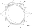
- FIG. 9 the recesses of the deflection part 7 are shown, which are provided corresponding to the said deflection regions as well as inlet regions and outlet regions.
- an electric motor from the described kit of parts can be produced, optionally with an electric motor FIG. 1 or an electric motor after FIG. 10 can be produced.
- the former motor with a cooling medium, ie liquid or gas can be cooled.
- the other engine can only give off heat to the surrounding air through its housing parts, in particular stator housing part 10.
- different variants can be produced with few components.
- cooling channel cross sections are shaped differently than the illustrated cooling channel cross sections. Insbeosndere they differ in form, number and order of the representations in the mentioned figures.
Landscapes
- Engineering & Computer Science (AREA)
- Power Engineering (AREA)
- Motor Or Generator Frames (AREA)
- Motor Or Generator Cooling System (AREA)
- Manufacture Of Motors, Generators (AREA)
- Iron Core Of Rotating Electric Machines (AREA)
Description
- Die Erfindung betrifft einen Elektromotor, einen Bausatz und ein Verfahren zur Herstellung.
- Es ist allgemein bekannt, bei Motoren das Rotorteil über Lager in einem Gehäuseteil zu lagern.
- Aus der
EP 0 924 839 B1 ist ein Elektromotor mit Mitteln zur Kühlung bekannt. - Aus der
EP 0 585 644 B1 ist eine oberflächengekühlte, geschlossene elektrische Maschine bekannt. - Aus der
DE 10 2a07 035 271 A1 - Aus der
DE 100 05 128 A1 ist ein kühlbarer Ständer für eine elektrische Maschine bekannt. - Der Erfindung liegt daher die Aufgabe zugrunde, eine kostengünstige Herstellung von Motoren zu ermöglichen.
- Erfindungsgemäß wird die Aufgabe bei dem Elektromotor nach den in Anspruch 1, bei dem Bausatz nach den in Anspruch 13 und bei dem Verfahren zur Herstellung nach den in Anspruch 15 angegebenen Merkmalen gelöst.
- Wichtige Merkmale der Erfindung bei dem Elektromotor sind, dass er ein das Statorblechpaket aufnehmendes Gehäuseteil aufweist, insbesondere ein das Statorblechpaket kraftschlüssig aufnehmendes Gehäuseteil,
wobei ein Flanschteil ein erstes Lager zur Lagerung der Rotorwelle aufnimmt,
wobei zwischen Flanschteil und Gehäuseteil ein Umlenkteil angeordnet ist,
wobei eine Schraubverbindung zwischen Flanschteil und Umlenkteil vorgesehen ist, die ein Gewindeteil umfasst,
wobei eine Schraubverbindung zwischen Umlenkteil und Gehäuseteil vorgesehen ist. - Von Vorteil ist dabei, dass durch die beiden Schraubverbindungen ermöglicht ist, dass das Flanschteil mit einer gleichartigen Schraubverbindung an ein andersartiges Gehäuseteil verbindbar ist und somit in einfacher Weise ein anderer Motor herstellbar ist. Indem also zwei Schraubverbindungen seriell vorgesehen sind, ist innerhalb einer Baureihe eine Schnittstelle zum Flanschteil hin erzeugbar, die innerhalb der Baureihe bei allen Varianten, also Elektromotoren, gleich bleibt. Somit sind Gehäuseteile mit verschiedenen Funktionalitäten mit dem Flanschteil verbindbar.
- Das Flanschteil ist an einem ersten axialen, also in Motorachsrichtung gesehenen Endbereich des Umlenkteils verbunden.
- Bei einer vorteilhaften Ausgestaltung ist bei der Schraubverbindung zwischen Flanschteil und Umlenkteil eine Schraube vorgesehen, die das Flanschteil berührt, insbesondere mit ihrem Schraubenkopf oder mit einer auf das Schraubgewinde der Schraube aufgeschraubter Mutter, und in das Gewindeteil eingeschraubt ist, insbesondere in ein Innengewinde des Gewindeteils, und das Gewindeteil in das Umlenkteil eingeschraubt ist. Von Vorteil ist dabei, dass einfache und kostengünstige Mittel zum Herstellen der Verbindungen verwendbar sind. Insbesondere durch das Gewindeteil ist eine Schraubverbindung mit dem Flanschteil und eine Schraubverbindung mit dem Umlenkteil ermöglicht.
- Bei einer vorteilhaften Ausgestaltung ist bei der Schraubverbindung zwischen Umlenkteil und Gehäuseteil eine Schraube vorgesehen, die das Umlenkteil berührt, insbesondere mit ihrem Schraubenkopf, und in das Gehäuseteil eingeschraubt ist. Von Vorteil ist dabei, dass die Schraube und weitere mechanische Schnittstelle unverändert einsetzbar ist bei Verbindung mit verschiedenen Stator-Gehäuseteilen.
- Bei einer vorteilhaften Ausgestaltung ist die Schraube der Schraubverbindung zwischen Umlenkteil und Gehäuseteil in ein Gewinde eingeschraubt, das in die Innenwand einer Ausnehmung eingeschnitten ist, die axial durchgängig durch das Gehäuseteil ist. Von Vorteil ist dabei, dass das Gehäuseteil als Stranggussteil fertigbar ist und somit kein zusätzlicher Aufwand notwendig ist.
- Bei einer vorteilhaften Ausgestaltung ist das Gehäuseteil ein Stranggussteil, insbesondere ein nachbearbeitetes Stranggussteil. Von Vorteil ist dabei, dass eine besonders einfache und kostengünstige Fertigung ermöglicht ist.
- Bei einer vorteilhaften Ausgestaltung ist eine Dichtung zwischen Umlenkteil und Gehäuseteil angeordnet, insbesondere eine Flachdichtung. Von Vorteil ist dabei, dass das Kühlmedium durchleitbar vom Gehäuseteil zum Flanschteil ist und im Umlenkteil abdichtbar.
- Bei einer vorteilhaften Ausgestaltung ist das Gewindeteil eine Gewindebuchse, die ein Innengewinde und ein Außengewinde aufweist. Die Gewindebuchse wird durch einen Innensechskant angezogen. Von Vorteil ist dabei, dass ein einfaches kostengünstiges Teil notwendig ist und somit eine Schnittstelle in der Baureihe zur Verfügung stellbar ist.
- Bei einer vorteilhaften Ausgestaltung weist das Gehäuseteil Kühlkanäle auf, insbesondere mehrere in axialer Richtung durchgängig verlaufende Kühlkanäle. Von Vorteil ist dabei, dass eine effektive Kühlung bereit stellbar ist.
- Bei einer vorteilhaften Ausgestaltung weist das Umlenkteil Umlenkbereiche, Einlassbereich und/oder Auslassbereich auf für das Kühlmedium,
insbesondere wobei am Umlenkteil eine Anschlussvorrichtung zum Einführen oder Herausführen von Kühlmedium angeordnet ist. Von Vorteil ist dabei, dass die Schnittstelle für die Zuleitung und Ableitung von Kühlmedium im Umlenkteil vorsehbar ist. - Bei einer vorteilhaften Ausgestaltung berührt das Gewindeteil das Flanschteil, insbesondere wobei ein Schraubenkopf oder eine Mutter das Gewindeteil berührt. Von Vorteil ist dabei, dass ein Abstützen des Gewindeteils am Flanschteil in axialer Richtung ausführbar ist.
- Bei einer vorteilhaften Ausgestaltung ist ein weiteres, ein die Rotorwelle lagerndes Lager aufnehmendes Flanschteil über eine entsprechende Schraubverbindung mit Gewindeteil mit einem weiteren Umlenkteil verbunden, das zwischen dem weiteren Flanschteil und dem Gehäuseteil angeordnet ist und mittels einer Schraubverbindung mit dem Gehäuseteil verbunden ist. Von Vorteil ist dabei, dass axial beidseitig die Schnittstelle für die Flanschteile innerhalb der Baureihe zur Verfügung stellbar ist.
- Bei einer vorteilhaften Ausgestaltung sind alle Ausnehmungen axial durchgängig und es ist ein Umlenkteil als Stranggussteil gefertigt.
- Zusätzlich oder alternativ ist zwischen jedem Umlenkteil und mittels Schraubverbindung verbundenem jeweiligem Flanschteil eine Dichtung, insbesondere Flachdichtung, angeordnet ist. Von Vorteil ist dabei, dass ein Begrenzen des Raumbereichs der Umlenkbereiche nicht nur durch das Umlenkteil und das Gehäuseteil sondern auch durch das Flanschteil ausführbar ist. Somit darf die Ausnehmung im Umlenkteil jeweils durchgängig sein.
- Wichtige Merkmale bei dem Bausatz zur wahlweisen Herstellung zweier Elektromotoren sind,
dass der erste Elektromotor ein das Statorblechpaket aufnehmendes Gehäuseteil aufweist,
wobei der zweite Elektromotor ein das Statorblechpaket aufnehmendes Gehäuseteil aufweist, das Kühlkanäle aufweist,
wobei der erste Elektromotor ein Gehäuseteil aufweist, an das ein Flanschteil schraubverbunden ist, das ein Lager zur Lagerung der Rotorwelle des zweiten Elektromotors aufweist, wobei eine ins Gehäuseteil eingeschraubte Schraube das Flanschteil berührt, insbesondere und an das Gehäuseteil andrückt,
wobei der zweite Elektromotor ein gleiches, insbesondere identisches, Flanschteil und eine gleiche, insbesondere identische, Schraube aufweist, die das Flanschteil berührt, und in ein Gewindeteil eingeschraubt ist, weiches in ein Umlenkteil eingeschraubt ist, welches mit einem Gehäuseteil des zweiten Elektromotors verbunden ist,
insbesondere wobei die axiale Länge des Gehäuseteils des ersten Motors der axialen Länge gleicht, welche die Einheit, insbesondere Statorgehäuseteil, aufweist, welche gebildet ist aus dem Gehäuseteil des zweiten Motors und den mit dem Gehäuseteil des zweiten Motors schraubverbundenen Umlenkteilen. - Von Vorteil ist dabei, dass aus dem Bausatz mit wenigen Teilen eine hohe Variantenvielfalt innerhalb der Baureihe erzeugbar ist. Denn die Flanschteile sind für alle Varianten gleich.
- Wichtige Merkmale bei dem Verfahren zur Herstellung zweier Elektromotoren aus einem Bausatz sind, dass jeweils Flanschteile mit einem Statorgehäuseteil verbunden sind,
wobei wahlweise - bei Herstellung des ersten Motors das ein Statorblechpaket aufnehmendes Statorgehäuseteil einstückig ausgeführt ist,
- Von Vorteil ist dabei, dass wiederum mit geringem Teileaufwand verschieden funktionale Motoren, also Varianten der Baureihe erzeugbar sind.
- Weitere Vorteile ergeben sich aus den Unteransprüchen. Die Erfindung ist nicht auf die Merkmalskombination der Ansprüche beschränkt. Für den Fachmann ergeben sich weitere sinnvolle Kombinationsmöglichkeiten von Ansprüchen und/oder einzelnen Anspruchsmerkmalen und/oder Merkmalen der Beschreibung und/oder der Figuren, insbesondere aus der Aufgabenstellung und/oder der sich durch Vergleich mit dem Stand der Technik stellenden Aufgabe.
- Die Erfindung wird nun anhand von Abbildungen näher erläutert:
DieFiguren 1 bis 9 beziehen sich auf eine erste Motorvariante einer Baureihe, die mit einem Kühlmedium kühlbar ist. DieFigur 10 bezieht sich hingegen auf eine Motorvariante der Baureihe, die nicht mittels eines Kühlmediums kühlbar ist. Somit ist aus einem Bausatz, weicher möglichst wenig Teile umfasst wahlweise entweder die erste oder zweite Variante herstellbar. - In der
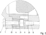
Figur 1 ist ein Schnitt durch einen mit einem Kühlmedium kühlbaren Elektromotor mit Umlenkteilen (15) gezeigt. - In der
Figur 2 ist ein vergrößerter Ausschnitt zurFigur 1 gezeigt. - In der
Figur 3 ist ein Umlenkteil 15 in Schrägansicht gezeigt. - In der
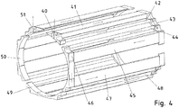
Figur 4 sind die Kühlkanäle und Umlenkberieche sowie Ein- und Auslassbereiche des Kühlmediums gezeigt, wobei Pfeile die wesentliche Flussrichtung andeuten. - In der
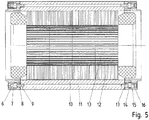
Figur 5 ist ein Stator des mit dem Kühlmedium kühlbaren Elektromotors gezeigt, der wahlweise ersetzbar ist durch einen Stator mit Gehäuseteil 160 gemäßFigur 10 . Je nach Wahl eines dieser beiden Statoren ist ein Elektromotor mit oder ohne durchs Kühlmedium bewirkbare Kühlung herstellbar. - In der
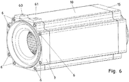
Figur 6 ist eine zurFigur 5 gehörige Schrägansicht gezeigt. - In
Figur 7 ist beim Ausführungsbeispiel nachFigur 6 das Gehäuseteil 10 weggenommen, so dass die Kühlkanalbereiche für das Kühlmedium sichtbar sind. - In
Figur 8 ist das Gehäuseteil 10 in Schrägansicht dargestellt. - In
Figur 9 ist das Umlenkteil 7 in Schrägansicht dargestellt. - In der
Figur 10 ist ein nicht mit dem Kühlmedium gekühlter Elektromotor gezeigt, wobei die Flanschteile und zugehörige Verbindungsschrauben dieselben sind wie beiFigur 1 . Somit ist die Mehrfache Verwendung des Flanschteils und der Verbindungsschrauben ersichtlich. - Wie in den
Figuren 1 bis 9 gezeigt ist bei der Motorvariante, bei der eine Kühlung mit Kühlmedium erreichbar ist, ein Flanschteil 1 vorgesehen, das auch bei der Motorvariante nachFigur 10 , also ohne Kühlung durch ein Kühlmedium, vorgesehen ist. - Somit umfasst der Bausatz einen Stator nach
Figur 5 , der aus einem Gehäuseteil 10 und den Umlenkteilen 7 und 15 zusammengesetzt ist, und einen inFigur 10 ersichtlichen Stator. Außerdem umfasst der Bausatz ein A-seitiges und ein B-seitiges Flanschteil (1, 3) sowie zugehörige Verbindungsmittel, - Die mechanische Schnittstelle am jeweiligen Flanschteil zum Stator hin ist stets gleich, so dass das jeweilige Flanschteil an beide Statoren verbindbar ist.
- Auf diese Weise ist also mit einer geringen Teilezahl eine hohe Varianz der in der Baureihe herstellbaren Varianten, also Motoren erreichbar.
- Gemäß
Figur 1 ist sind auf einer Rotorwelle 20 Permanentmagnete 13 angeordnet und somit der Motor als Synchronmotor ausgeführt. Alternativ oder zusätzlich ist auf der Rotorwelle auch ein Kurzschlusskäfig vorsehbar zur Ausführung als Asynchronmotor oder LSPM-Motor. - Die Rotorwelle 20 ist mittels des Lagers 19 im Flanschteil 1 gelagert und mittels des Lagers 18 im Flanschteil 3 gelagert.
- Das Statorblechpaket 12 ist beispielhaft stanzpaketiert und kraftschlüssig im Gehäuseteil 10 eingefügt. Im Statorblechpaket 12 ist die Statorwicklung aufgenommen. Die Umlenkbereiche der Statorwicklung ragen in die axialen Bereiche hinein, welche auch von den Umlenkteilen (7, 15) überdeckt sind.
- Eine Verbindungsschraube 2, insbesondere wie in
Figur 2 gezeigt, ist durch eine Bohrung des Flanschteiles 1 hindurchgeführt und in ein Innengewinde 21 einer Gewindebuchse 6 eingeschraubt, deren Außengewinde 22 in einer Gewindebohrung des Umlenkteils 7 eingeschraubt ist. - Zur Aufnahme der Gewindebuchse 6 im Umlenkteil 7 weist dieses eine gestufte Bohrung auf, so dass die Gewindebuchse in demjenigen Bereich der gestuften Bohrung, welcher einen größeren Innendurchmesser aufweist, aufnehmbar ist. Durch den Bereich der gestuften Bohrung mit kleinerem Innendurchmesser ist eine Verbindungsschraube 8 geführt, wobei deren Schraubenkopf im Bereich größeren Innendurchmessers der gestuften Bohrung angeordnet ist und einen größeren Durchmesser aufweist als der Innendurchmesser im Bereich der gestuften Bohrung mit kleineren Innendurchmesser. Die Schraube 8 ist mir ihrem Gewinde in eine Gewindebohrung des Gehäuseteils 10 eingeschraubt.
- Die Gewindebohrung ist hierbei in einer Ausnehmung 11 eingebracht, die axial langgestreckt ausgeführt ist, da das Gehäuseteil 10 als Stranggussteil, insbesondere Aluminium-Stranggussteil, hergestellt ist und somit die Ausnehmung 11 in axialer Richtung durchgängig ist.
- B-seitig ist eine entsprechende Schnittstelle geschaffen, indem das Flanschteil 3 mittels der Verbindungsschraube 4 in eine Gewindebuchse 16 eingeschraubt ist und diese wiederum mit ihrem Außengewinde in den Bereich mit größerem Innendurchmesser einer gestuften Bohrung im Umlenkteil 15 eingeschraubt ist. Ebenso ist auch eine Verbindungsschraube 14 vorgesehen, mit der das Umlenkteil 15 verschraubt ist mit dem Gehäuseteil 10 zur Bildung eines Stator-Gehäuseteils. Dabei ist auch die Verbindungsschraube 14 in ein Gewinde eingeschraubt, welches in der Ausnehmung 11 des Gehäuseteils 10 durchgängig ausgeführt ist. Der Schraubenkopf der Verbindungsschraube 14 weist ebenfalls einen größeren Durchmesser auf als der Innendurchmesser desjenigen Bereiches der gestuften Bohrung beträgt, welcher einen kleineren Durchmesser aufweist, also im Stufenbereich mit kleinerem Durchmesser vorgesehen ist.
- Mittels der Schraubverbindung zwischen Umlenkteil 7 und Gehäuseteil 10 und entsprechender Schraubverbindung zwischen dem weiteren Umlenkteil 15 und Gehäuseteil 10 ist somit ein dreistückig ausgeführtes Statorgehäuseteil hergestellt.
- Zur Herstellung des Elektromotors, also einer Variante der Baureihe, wird nun entweder dieses dreistückig ausgeführte Statorgehäuseteil oder alternativ das einstückige Statorgehäuseteil 160 mit der zur Ausnehmung 11 korrespondierenden Ausnehmung 161 gewählt. In jedem Fall sind die Flanschteile (1, 3) mit ihren zugehörigen Verbindungsschrauben 2 beziehungsweise 4 an die Statorgehäuseteile angeschraubt.
- Das Kühlmedium 9 in einem Umlenkbereich des Umlenkteils 7 ist in
Figur 1 angedeutet. Zwischen den Umlenkteilen (7, 15) und dem Gehäuseteil 10 ist jeweils eine Dichtung 23 vorgesehen, die vorzugsweise als Flachdichtung ausgeführt ist. - In
Figur 3 ist das Umlenkteil 15 näher dargestellt, wobei die Bohrungen 31 zur Aufnahme der Gewindebuchse 16 näher dargestellt sind. Außerdem sind Umlenkbereiche 30 gezeigt, in welche jeweils eingehende und ausgehende Kühlkanäle münden. - In der
Figur 4 ist das Kühlmedium beziehungsweise die das Kühlmedium führenden Bereiche gezeigt. - Durch den Einlass 40 für Kühlmedium, insbesondere Gas oder Flüssigkeit, insbesondere Öl oder Wasser, gelangt das Kühlmedium in einen ersten Einlassbereich aus dem ein breiter Kühlkanal 41 und ein schmaler runder Kühlkanal 42 herausgehen. Diese münden an der axial gegenüberliegenden Seite des Stators in einen Umlenkbereich 43, aus welchem wiederum ein breiter Kühlkanal 45 und ein schmaler runder Kühlkanal 44 herausführen - allerdings in axial entgegengesetzter Richtung.
- Entsprechend münden diese Kanäle wiederum in einem Umlenkbereich 46, aus dem wiederum ein breiter Kühlkanal 47 und ein schmaler Kühlkanal herausführen und über einen Umlenkbereich am anderen axialen Ende umgelenkt werden.
- Die Kühlkanäle sind im Beriech des Gehäuseteils 10, das als Stranggussteil ausgeführt ist, durchgängig ausgeführt.
- Somit wird das Kühlmedium in axialer Richtung und Umfangsrichtung mäanderförmig geführt, wobei es in axialer Richtung hin- und hergeführt wird.
- Weitere in
Figur 4 sichtbare Umlenkbereiche sind Umlenkbereich 49 und 50. - Schließlich wird das Kühlmedium im Bereich des Auslasses 51 herausgeführt.
- Die Anschlussbereiche (60, 61) für Auslass und Einlass des Kühlmediums am Umlenkteil 7 sind in
Figur 6 gezeigt. - In
Figur 8 ist das Gehäuseteil mit Stator gezeigt, wobei es als Stranggussprofil gefertigt ist und nach dem Strangguss-Fertigen nachbearbeitet wird, um die Schnittstelle zu den Flanschteilen mit einem Zentrierabschnitt auszugestalten. Die Ausnehmungen (11, 42, 44, 45) werden beim Stranggussziehen vorgesehen und erstrecken sich somit über die ganze axiale Länge des Stranggussprofils. - Die Umlenkteile (7,15) werden nur durch die Befestigungsschrauben (8, 14) zum Gehäuse 10 zentriert und ausgerichtet. Ein runder Zentriersitz ist an den Flanschteilen (1, 3) zur Verbindung mit den Umlenkteilen (7, 15) vorgesehen.
- Statt der Befestigungsschrauben (8, 14) sidn bei anderen Ausführungsbeispielen auch zusätzliche Passstifte verwendbar.
- In
Figur 9 sind die Ausnehmungen des Umlenkteils 7 gezeigt, welche korrespondierend zu den genannten Umlenkbereichen sowie Einlassbereichen und Auslassbereichen vorgesehen sind. - Somit ist also ein Elektromotor aus dem beschriebenen Bausatz von Teilen herstellbar, wobei wahlweise ein Elektromotor nach
Figur 1 oder ein Elektromotor nachFigur 10 herstellbar ist. Dabei ist der erstgenannte Motor mit einem Kühlmedium, also Flüssigkeit oder Gas, kühlbar. Der andere Motor hingegen kann nur Wärme an die umgebende Luft abgeben über seine Gehäuseteile, insbesondere Statorgehäuseteil 10. Somit sind mit wenigen Bauteilen verschieden Varianten herstellbar. - In weiteren erfindungsgemäßen Ausführungsbeispielen sind die Kühlkanalquerschnitte anders geformt als die dargestellten Kühlkanalquerschnitte. Insbeosndere unterscheiden sie sich in Form, Anzahl und Ordnung von den Darstellungen in den genannten Figuren.
-
- 1
- Flanschteil
- 2
- Verbindungsschraube
- 3
- Flanschteil
- 4
- Verbindungsschraube
- 6
- Gewindebuchse
- 7
- Umlenkteil
- 8
- Verbindungsschraube
- 9
- Kühlmedium
- 10
- Gehäuseteil
- 11
- Ausnehmung
- 12
- Statorblechpaket
- 13
- Dauermagnete
- 14
- Verbindungsschraube
- 15
- zweites Umlenkteil
- 16
- Gewindebuchse
- 17
- Kühlmedium
- 18
- Lager
- 19
- Lager
- 20
- Rotorwelle
- 21
- Innengewinde der Gewindebuchse 6
- 22
- Außengewinde der Gewindebuchse 6
- 23
- Dichtung, insbesondere Flachdichtung
- 30
- Umlenkbereich
- 31
- Bohrung für Verbindungsschraube 14
- 40
- Einlass für Kühlmedium
- 41
- breiter Kühlkanal
- 42
- schmaler runder Kühlkanal
- 43
- Umlenkbereich
- 44
- schmaler Kühlkanal
- 45
- breiter Kühlkanal
- 46
- Umlenkbereich
- 47
- breiter Kühlkanal
- 48
- schmaler Kühlkanal
- 49
- Umlenkbereich
- 50
- Umlenkbereich
- 51
- Auslass für Kühlmedium
- 60
- Anschlussbereich für Auslass des Kühlmediums
- 61
- Anschlussbereich für Einlass des Kühlmediums
- 90
- Einlassbereich
- 91
- Umlenkbereich
- 92
- Umlenkbereich
- 93
- Umlenkbereich
- 94
- Umlenkbereich
- 160
- Gehäuseteil
- 161
- Ausnehmung
Claims (15)
- Elektromotor,
aufweisend ein das Statorblechpaket (12) aufnehmendes Gehäuseteil, insbesondere ein das Statorblechpaket (12) kraftschlüssig aufnehmendes Gehäuseteil,
wobei ein Flanschteil (1, 3) ein erstes Lager (18, 19) zur Lagerung der Rotorwelle (20) aufnimmt,
dadurch gekennzeichnet, dass
zwischen Flanschteil (1, 3) und Gehäuseteil ein Umlenkteil (7) zur Umlenkung eines Kühlmittelstromes angeordnet ist,
wobei eine Schraubverbindung zwischen Flanschteil (1, 3) und Umlenkteil (7) vorgesehen ist, die ein Gewindeteil umfasst,
wobei eine Schraubverbindung zwischen Umlenkteil (7) und Gehäuseteil vorgesehen ist. - Elektromotor nach Anspruch 1,
dadurch gekennzeichnet, dass
bei der Schraubverbindung zwischen Flanschteil (1, 3) und Umlenkteil (7) eine Schraube vorgesehen ist, die das Flanschteil (1, 3) berührt, insbesondere mit ihrem Schraubenkopf oder mit einer auf das Schraubgewinde der Schraube aufgeschraubter Mutter, und in das Gewindeteil eingeschraubt ist, insbesondere in ein Innengewinde (21) des Gewindeteils, und das Gewindeteil in das Umlenkteil (7) eingeschraubt ist. - Elektromotor nach mindestens einem der vorangegangenen Ansprüche,
dadurch gekennzeichnet, dass
bei der Schraubverbindung zwischen Umlenkteil (7) und Gehäuseteil eine Schraube vorgesehen ist, die das Umlenkteil (7) berührt, insbesondere mit ihrem Schraubenkopf, und in das Gehäuseteil eingeschraubt ist. - Elektromotor nach mindestens einem der vorangegangenen Ansprüche,
dadurch gekennzeichnet, dass
die Schraube der Schraubverbindung zwischen Umlenkteil (7) und Gehäuseteil in ein Gewinde eingeschraubt ist, das in die Innenwand einer Ausnehmung (11, 161) eingeschnitten ist, die axial durchgängig durch das Gehäuseteil ist. - Elektromotor nach mindestens einem der vorangegangenen Ansprüche,
dadurch gekennzeichnet, dass
das Gehäuseteil ein Stranggussteil ist, insbesondere ein nachbearbeitetes Stranggussteil. - Elektromotor nach mindestens einem der vorangegangenen Ansprüche,
dadurch gekennzeichnet, dass
eine Dichtung (23) zwischen Umlenkteil (7) und Gehäuseteil angeordnet ist, insbesondere eine Flachdichtung. - Elektromotor nach mindestens einem der vorangegangenen Ansprüche,
dadurch gekennzeichnet, dass
das Gewindeteil eine Gewindebuchse (6, 16) ist, die ein Innengewinde (21) und ein Außengewinde (22) aufweist,
insbesondere wobei die Gewindebuchse (6, 16) eine Schnittstelle zum Ansetzen eines Werkzeugs aufweist, so dass ein Anziehen ermöglicht ist,
insbesondere wobei die Schnittstelle ein Innensechskant ist. - Elektromotor nach mindestens einem der vorangegangenen Ansprüche,
dadurch gekennzeichnet, dass
das Gehäuseteil Kühlkanäle aufweist, insbesondere mehrere in axialer Richtung durchgängig verlaufende Kühlkanäle. - Elektromotor nach mindestens einem der vorangegangenen Ansprüche,
dadurch gekennzeichnet, dass
das Umlenkteil (7) Umlenkbereiche (30, 43, 46, 49, 50, 91, 92, 93, 94), Einlassbereich (90) und/oder Auslassbereich (51) aufweist für das Kühlmedium (9, 17),
insbesondere wobei am Umlenkteil (7) eine Anschlussvorrichtung zum Einführen oder Herausführen von Kühlmedium (9, 17) angeordnet ist. - Elektromotor nach mindestens einem der vorangegangenen Ansprüche,
dadurch gekennzeichnet, dass
das Gewindeteil das Flanschteil (1, 3) berührt, insbesondere wobei ein Schraubenkopf oder eine Mutter das Gewindeteil berührt. - Elektromotor nach mindestens einem der vorangegangenen Ansprüche,
dadurch gekennzeichnet, dass
ein weiteres, ein die Rotorwelle (20) lagerndes Lager (18, 19) aufnehmendes Flanschteil (1, 3) über eine entsprechende Schraubverbindung mit Gewindeteil mit einem weiteren Umlenkteil (15) verbunden ist, das zwischen dem weiteren Flanschteil (1, 3) und dem Gehäuseteil angeordnet ist und mittels einer Schraubverbindung mit dem Gehäuseteil verbunden ist. - Elektromotor nach mindestens einem der vorangegangenen Ansprüche,
dadurch gekennzeichnet, dass
ein Umlenkteil (7) als Strangguss gefertigt ist, insbesondere so dass alle Ausnehmungen (11, 161) axial durchgängig sind,
und/oder dass zwischen jedem Umlenkteil (7, 15) und mittels Schraubverbindung verbundenem jeweiligem Flanschteil (1, 3) eine Dichtung (23), insbesondere Flachdichtung angeordnet ist. - Bausatz zur wahlweisen Herstellung zweier Elektromotoren,
wobei der erste Elektromotor ein das Statorblechpaket (12) aufnehmendes Gehäuseteil aufweist,
wobei der zweite Elektromotor ein Elektromotor nach einem der vorangegangenen Ansprüche ist, der ein das Statorblechpaket (12) aufnehmendes Gehäuseteil aufweist, das Kühlkanäle aufweist,
dadurch gekennzeichnet, dass
der erste Elektromotor ein Gehäuseteil aufweist, an das ein Flanschteil (1, 3) schraubverbunden ist, das ein Lager (18, 19) zur Lagerung der Rotorwelle (20) des zweiten Elektromotors aufweist, wobei eine ins Gehäuseteil eingeschraubte Schraube das Flanschteil (1, 3) berührt, insbesondere und an das Gehäuseteil andrückt,
wobei der zweite Elektromotor ein gleiches, insbesondere identisches, Flanschteil (1, 3) und eine gleiche, insbesondere identische, Schraube aufweist, die das Flanschteil (1, 3) berührt, und in ein Gewindeteil eingeschraubt ist, weiches in ein Umlenkteil (7) zur Umlenkung eines Külmittelstromes eingeschraubt ist, welches mit einem Gehäuseteil des zweiten Elektromotors verbunden ist,
insbesondere wobei die axiale Länge des Gehäuseteils des ersten Motors der axialen Länge gleicht, welche die Einheit, insbesondere Statorgehäuseteil, aufweist, welche gebildet ist aus dem Gehäuseteil des zweiten Motors und den mit dem Gehäuseteil des zweiten Motors schraubverbundenen Umlenkteilen (7, 15). - Bausatz nach Anspruch 13,
dadurch gekennzeichnet, dass
das Gehäuseteil des ersten und zweiten Motors aus dem gleichen Stranggussprofil gefertigt sind, insbesondere denselben Querschnitt aufweisen. - Verfahren zur Herstellung zweier Elektromotoren aus einem Bausatz nach Anspruch 13, wobei jeweils Flanschteile (1,3) mit einem Statorgehäuseteil verbunden sind,
dadurch gekennzeichnet, dass
wahlweise- bei Herstellung des ersten Motors ein Statorblechpaket (12) aufnehmendes Statorgehäuseteil einstückig ausgeführt ist,- bei Herstellung des zweiten Motors das Statorgehäuseteil aus zwei Umlenkteilen (7, 15) zur Umlenkung eines Kühlmittelstromes und einem das Statorblechpaket (12) aufnehmenden Gehäuseteil zusammengesetzt ist, insbesondere wobei jedes Umlenkteil (7, 15) mittels Schraubverbindungen mit dem Gehäuseteil verbunden ist und zumindest eines der Umlenkteile (7, 15) eine Anschlussvorrichtung für eine Kühlmittelzufuhr oder Kühlmittelabfuhr aufweist.
Applications Claiming Priority (2)
| Application Number | Priority Date | Filing Date | Title |
|---|---|---|---|
| DE102010050348.7A DE102010050348B4 (de) | 2010-11-05 | 2010-11-05 | Elektromotor und Bausatz zu seiner Herstellung |
| PCT/EP2011/004676 WO2012059154A2 (de) | 2010-11-05 | 2011-09-19 | Elektromotor, bausatz und verfahren zur herstellung |
Publications (2)
| Publication Number | Publication Date |
|---|---|
| EP2636128A2 EP2636128A2 (de) | 2013-09-11 |
| EP2636128B1 true EP2636128B1 (de) | 2018-05-30 |
Family
ID=44675531
Family Applications (1)
| Application Number | Title | Priority Date | Filing Date |
|---|---|---|---|
| EP11760706.9A Active EP2636128B1 (de) | 2010-11-05 | 2011-09-19 | Elektromotor, bausatz und verfahren zur herstellung |
Country Status (3)
| Country | Link |
|---|---|
| EP (1) | EP2636128B1 (de) |
| DE (1) | DE102010050348B4 (de) |
| WO (1) | WO2012059154A2 (de) |
Cited By (1)
| Publication number | Priority date | Publication date | Assignee | Title |
|---|---|---|---|---|
| WO2024133516A1 (en) * | 2022-12-22 | 2024-06-27 | Valeo Eautomotive Germany Gmbh | Stator for an electric machine, electric machine and method for manufacturing a stator |
Families Citing this family (9)
| Publication number | Priority date | Publication date | Assignee | Title |
|---|---|---|---|---|
| DE102011119603B4 (de) * | 2011-11-29 | 2021-07-01 | Sew-Eurodrive Gmbh & Co Kg | Elektromotor |
| US9729028B2 (en) * | 2012-10-04 | 2017-08-08 | Mitsubishi Electric Corporation | Rotary electric machine having integrated drive control device |
| DE102012022481A1 (de) * | 2012-11-19 | 2014-05-22 | Sew-Eurodrive Gmbh & Co Kg | Elektromotor mit einem Stator |
| DE102016119243B4 (de) | 2016-10-10 | 2023-08-17 | Volkswagen Aktiengesellschaft | Stator für eine elektrische Maschine eines Fahrzeugs, elektrische Maschine eines Fahrzeugs sowie Fahrzeug |
| DE102018009527A1 (de) | 2018-12-07 | 2020-06-10 | Wilo Se | Elektromotor mit Montageflansch |
| WO2020126075A1 (de) * | 2018-12-18 | 2020-06-25 | Sew-Eurodrive Gmbh & Co. Kg | Elektromotor mit einem statorgehäuseteil |
| EP3900160A1 (de) * | 2018-12-20 | 2021-10-27 | Sew-Eurodrive GmbH & Co. KG | Elektromotor mit einem statorgehäuseteil |
| DE102021109736B4 (de) | 2021-04-19 | 2023-02-23 | Schaeffler Technologies AG & Co. KG | Elektrisch betreibbarer Achsantriebsstrang |
| WO2023110382A1 (de) | 2021-12-13 | 2023-06-22 | Sew-Eurodrive Gmbh & Co. Kg | Elektromotor mit elektromagnetisch betätigbarer bremse |
Family Cites Families (6)
| Publication number | Priority date | Publication date | Assignee | Title |
|---|---|---|---|---|
| EP0585644B1 (de) | 1992-09-03 | 1997-05-14 | FHP Motors GmbH | Oberflächengekühlte, geschlossene elektrische Maschine |
| DE29722432U1 (de) | 1997-12-18 | 1998-02-26 | Siemens AG, 80333 München | Elektromotor |
| DE10005128B4 (de) * | 2000-02-07 | 2004-03-25 | Baumüller Nürnberg GmbH | Kühlbarer Ständer für eine elektrische Maschine |
| DE102007035271A1 (de) | 2007-07-27 | 2009-01-29 | Continental Automotive Gmbh | Elektromotor |
| DE102008017643B4 (de) * | 2008-04-04 | 2016-09-15 | Sew-Eurodrive Gmbh & Co Kg | Adapter, Getriebe und Antrieb |
| DE102009005885A1 (de) * | 2009-01-23 | 2010-07-29 | Robert Bosch Gmbh | Servoantrieb und Verfahren zum Herstellen eines Servoantriebs |
-
2010
- 2010-11-05 DE DE102010050348.7A patent/DE102010050348B4/de active Active
-
2011
- 2011-09-19 WO PCT/EP2011/004676 patent/WO2012059154A2/de not_active Ceased
- 2011-09-19 EP EP11760706.9A patent/EP2636128B1/de active Active
Non-Patent Citations (1)
| Title |
|---|
| None * |
Cited By (1)
| Publication number | Priority date | Publication date | Assignee | Title |
|---|---|---|---|---|
| WO2024133516A1 (en) * | 2022-12-22 | 2024-06-27 | Valeo Eautomotive Germany Gmbh | Stator for an electric machine, electric machine and method for manufacturing a stator |
Also Published As
| Publication number | Publication date |
|---|---|
| DE102010050348A1 (de) | 2012-05-10 |
| WO2012059154A3 (de) | 2013-05-23 |
| WO2012059154A2 (de) | 2012-05-10 |
| EP2636128A2 (de) | 2013-09-11 |
| DE102010050348B4 (de) | 2022-05-25 |
Similar Documents
| Publication | Publication Date | Title |
|---|---|---|
| EP2636128B1 (de) | Elektromotor, bausatz und verfahren zur herstellung | |
| EP2002526B1 (de) | Elektrische maschine | |
| DE10041805B4 (de) | Kühlvorrichtung mit einem luftdurchströmten Kühler | |
| EP3649724B1 (de) | Verfahren zur herstellung eines rotors für einen elektromotor und mit diesem verfahren hergestellter rotor | |
| EP2399334B1 (de) | Traktionsmotor mit einem gehäuse | |
| EP2790299B1 (de) | Statorkernbaugruppe | |
| EP0376178A1 (de) | Werkzeugmaschine mit gekühlter Motorspindel | |
| WO2021032240A1 (de) | Stator und elektrische rotationsmaschine | |
| EP3480929B1 (de) | Gekühltes gehäuse für den stator eines direktantriebs | |
| DE102013018720A1 (de) | Kurbelwellen-Startergenerator und Gehäuse für einen Kurbelwellen-Startergenerator | |
| DE102021131448A1 (de) | Kühlvorrichtung für einen Stator mit Kühlmantel außerhalb eines Innengehäuseteils | |
| DE102022213027A1 (de) | Rotor und elektrische Maschine | |
| WO2018054599A1 (de) | Elektrische antriebseinheit mit kühlhülse | |
| DE102011008523A1 (de) | Elektromotor | |
| EP2569853A2 (de) | Rotor für eine dynamoelektrische maschine | |
| DE69936693T2 (de) | Elektromotor zum Anflanschen an ein Getriebe, insbesondere an ein Kraftfahrzeuggetriebe | |
| EP3619795B1 (de) | Elektrische maschine mit kühlung | |
| DE102011119603B4 (de) | Elektromotor | |
| DE102014007213A1 (de) | Verbindung eines ersten Teils mit einem zweiten Teil und Antrieb | |
| AT508879B1 (de) | Luftgekühlte elektrische maschine | |
| DE102014210915A1 (de) | Elektrowerkzeugmaschine | |
| DE102020114748A1 (de) | Elektrische Maschine mit gehäuseseitiger Anbindung eines Stators | |
| WO2021047729A1 (de) | Elektrische maschine mit einer bestimmten positionierung verschiedener vertiefungen an einem nass laufenden stator | |
| DE102021132595B4 (de) | Elektrisches Antriebssystem mit zwei Antriebsmaschinen und gehäuseseitiger Statorverschraubung | |
| DE10203406C2 (de) | Elektromotor und Baureihe |
Legal Events
| Date | Code | Title | Description |
|---|---|---|---|
| PUAI | Public reference made under article 153(3) epc to a published international application that has entered the european phase |
Free format text: ORIGINAL CODE: 0009012 |
|
| AK | Designated contracting states |
Kind code of ref document: A2 Designated state(s): AL AT BE BG CH CY CZ DE DK EE ES FI FR GB GR HR HU IE IS IT LI LT LU LV MC MK MT NL NO PL PT RO RS SE SI SK SM TR |
|
| AX | Request for extension of the european patent |
Extension state: BA ME |
|
| 17P | Request for examination filed |
Effective date: 20131125 |
|
| RBV | Designated contracting states (corrected) |
Designated state(s): AL AT BE BG CH CY CZ DE DK EE ES FI FR GB GR HR HU IE IS IT LI LT LU LV MC MK MT NL NO PL PT RO RS SE SI SK SM TR |
|
| DAX | Request for extension of the european patent (deleted) | ||
| GRAP | Despatch of communication of intention to grant a patent |
Free format text: ORIGINAL CODE: EPIDOSNIGR1 |
|
| INTG | Intention to grant announced |
Effective date: 20180111 |
|
| GRAS | Grant fee paid |
Free format text: ORIGINAL CODE: EPIDOSNIGR3 |
|
| GRAA | (expected) grant |
Free format text: ORIGINAL CODE: 0009210 |
|
| AK | Designated contracting states |
Kind code of ref document: B1 Designated state(s): AL AT BE BG CH CY CZ DE DK EE ES FI FR GB GR HR HU IE IS IT LI LT LU LV MC MK MT NL NO PL PT RO RS SE SI SK SM TR |
|
| REG | Reference to a national code |
Ref country code: GB Ref legal event code: FG4D Free format text: NOT ENGLISH |
|
| REG | Reference to a national code |
Ref country code: CH Ref legal event code: EP |
|
| REG | Reference to a national code |
Ref country code: AT Ref legal event code: REF Ref document number: 1004610 Country of ref document: AT Kind code of ref document: T Effective date: 20180615 |
|
| REG | Reference to a national code |
Ref country code: IE Ref legal event code: FG4D Free format text: LANGUAGE OF EP DOCUMENT: GERMAN |
|
| REG | Reference to a national code |
Ref country code: DE Ref legal event code: R096 Ref document number: 502011014260 Country of ref document: DE |
|
| REG | Reference to a national code |
Ref country code: FR Ref legal event code: PLFP Year of fee payment: 8 |
|
| REG | Reference to a national code |
Ref country code: NL Ref legal event code: MP Effective date: 20180530 |
|
| REG | Reference to a national code |
Ref country code: LT Ref legal event code: MG4D |
|
| PG25 | Lapsed in a contracting state [announced via postgrant information from national office to epo] |
Ref country code: FI Free format text: LAPSE BECAUSE OF FAILURE TO SUBMIT A TRANSLATION OF THE DESCRIPTION OR TO PAY THE FEE WITHIN THE PRESCRIBED TIME-LIMIT Effective date: 20180530 Ref country code: BG Free format text: LAPSE BECAUSE OF FAILURE TO SUBMIT A TRANSLATION OF THE DESCRIPTION OR TO PAY THE FEE WITHIN THE PRESCRIBED TIME-LIMIT Effective date: 20180830 Ref country code: NO Free format text: LAPSE BECAUSE OF FAILURE TO SUBMIT A TRANSLATION OF THE DESCRIPTION OR TO PAY THE FEE WITHIN THE PRESCRIBED TIME-LIMIT Effective date: 20180830 Ref country code: CY Free format text: LAPSE BECAUSE OF FAILURE TO SUBMIT A TRANSLATION OF THE DESCRIPTION OR TO PAY THE FEE WITHIN THE PRESCRIBED TIME-LIMIT Effective date: 20180530 Ref country code: ES Free format text: LAPSE BECAUSE OF FAILURE TO SUBMIT A TRANSLATION OF THE DESCRIPTION OR TO PAY THE FEE WITHIN THE PRESCRIBED TIME-LIMIT Effective date: 20180530 Ref country code: LT Free format text: LAPSE BECAUSE OF FAILURE TO SUBMIT A TRANSLATION OF THE DESCRIPTION OR TO PAY THE FEE WITHIN THE PRESCRIBED TIME-LIMIT Effective date: 20180530 Ref country code: SE Free format text: LAPSE BECAUSE OF FAILURE TO SUBMIT A TRANSLATION OF THE DESCRIPTION OR TO PAY THE FEE WITHIN THE PRESCRIBED TIME-LIMIT Effective date: 20180530 |
|
| PG25 | Lapsed in a contracting state [announced via postgrant information from national office to epo] |
Ref country code: LV Free format text: LAPSE BECAUSE OF FAILURE TO SUBMIT A TRANSLATION OF THE DESCRIPTION OR TO PAY THE FEE WITHIN THE PRESCRIBED TIME-LIMIT Effective date: 20180530 Ref country code: RS Free format text: LAPSE BECAUSE OF FAILURE TO SUBMIT A TRANSLATION OF THE DESCRIPTION OR TO PAY THE FEE WITHIN THE PRESCRIBED TIME-LIMIT Effective date: 20180530 Ref country code: GR Free format text: LAPSE BECAUSE OF FAILURE TO SUBMIT A TRANSLATION OF THE DESCRIPTION OR TO PAY THE FEE WITHIN THE PRESCRIBED TIME-LIMIT Effective date: 20180831 Ref country code: HR Free format text: LAPSE BECAUSE OF FAILURE TO SUBMIT A TRANSLATION OF THE DESCRIPTION OR TO PAY THE FEE WITHIN THE PRESCRIBED TIME-LIMIT Effective date: 20180530 |
|
| PG25 | Lapsed in a contracting state [announced via postgrant information from national office to epo] |
Ref country code: NL Free format text: LAPSE BECAUSE OF FAILURE TO SUBMIT A TRANSLATION OF THE DESCRIPTION OR TO PAY THE FEE WITHIN THE PRESCRIBED TIME-LIMIT Effective date: 20180530 |
|
| PG25 | Lapsed in a contracting state [announced via postgrant information from national office to epo] |
Ref country code: EE Free format text: LAPSE BECAUSE OF FAILURE TO SUBMIT A TRANSLATION OF THE DESCRIPTION OR TO PAY THE FEE WITHIN THE PRESCRIBED TIME-LIMIT Effective date: 20180530 Ref country code: PL Free format text: LAPSE BECAUSE OF FAILURE TO SUBMIT A TRANSLATION OF THE DESCRIPTION OR TO PAY THE FEE WITHIN THE PRESCRIBED TIME-LIMIT Effective date: 20180530 Ref country code: DK Free format text: LAPSE BECAUSE OF FAILURE TO SUBMIT A TRANSLATION OF THE DESCRIPTION OR TO PAY THE FEE WITHIN THE PRESCRIBED TIME-LIMIT Effective date: 20180530 Ref country code: SK Free format text: LAPSE BECAUSE OF FAILURE TO SUBMIT A TRANSLATION OF THE DESCRIPTION OR TO PAY THE FEE WITHIN THE PRESCRIBED TIME-LIMIT Effective date: 20180530 Ref country code: CZ Free format text: LAPSE BECAUSE OF FAILURE TO SUBMIT A TRANSLATION OF THE DESCRIPTION OR TO PAY THE FEE WITHIN THE PRESCRIBED TIME-LIMIT Effective date: 20180530 Ref country code: RO Free format text: LAPSE BECAUSE OF FAILURE TO SUBMIT A TRANSLATION OF THE DESCRIPTION OR TO PAY THE FEE WITHIN THE PRESCRIBED TIME-LIMIT Effective date: 20180530 |
|
| PG25 | Lapsed in a contracting state [announced via postgrant information from national office to epo] |
Ref country code: IT Free format text: LAPSE BECAUSE OF FAILURE TO SUBMIT A TRANSLATION OF THE DESCRIPTION OR TO PAY THE FEE WITHIN THE PRESCRIBED TIME-LIMIT Effective date: 20180530 Ref country code: SM Free format text: LAPSE BECAUSE OF FAILURE TO SUBMIT A TRANSLATION OF THE DESCRIPTION OR TO PAY THE FEE WITHIN THE PRESCRIBED TIME-LIMIT Effective date: 20180530 |
|
| REG | Reference to a national code |
Ref country code: DE Ref legal event code: R097 Ref document number: 502011014260 Country of ref document: DE |
|
| PLBE | No opposition filed within time limit |
Free format text: ORIGINAL CODE: 0009261 |
|
| STAA | Information on the status of an ep patent application or granted ep patent |
Free format text: STATUS: NO OPPOSITION FILED WITHIN TIME LIMIT |
|
| PG25 | Lapsed in a contracting state [announced via postgrant information from national office to epo] |
Ref country code: MC Free format text: LAPSE BECAUSE OF FAILURE TO SUBMIT A TRANSLATION OF THE DESCRIPTION OR TO PAY THE FEE WITHIN THE PRESCRIBED TIME-LIMIT Effective date: 20180530 |
|
| REG | Reference to a national code |
Ref country code: CH Ref legal event code: PL |
|
| 26N | No opposition filed |
Effective date: 20190301 |
|
| PG25 | Lapsed in a contracting state [announced via postgrant information from national office to epo] |
Ref country code: SI Free format text: LAPSE BECAUSE OF FAILURE TO SUBMIT A TRANSLATION OF THE DESCRIPTION OR TO PAY THE FEE WITHIN THE PRESCRIBED TIME-LIMIT Effective date: 20180530 |
|
| REG | Reference to a national code |
Ref country code: BE Ref legal event code: MM Effective date: 20180930 |
|
| REG | Reference to a national code |
Ref country code: IE Ref legal event code: MM4A |
|
| PG25 | Lapsed in a contracting state [announced via postgrant information from national office to epo] |
Ref country code: LU Free format text: LAPSE BECAUSE OF NON-PAYMENT OF DUE FEES Effective date: 20180919 |
|
| PG25 | Lapsed in a contracting state [announced via postgrant information from national office to epo] |
Ref country code: IE Free format text: LAPSE BECAUSE OF NON-PAYMENT OF DUE FEES Effective date: 20180919 |
|
| PG25 | Lapsed in a contracting state [announced via postgrant information from national office to epo] |
Ref country code: BE Free format text: LAPSE BECAUSE OF NON-PAYMENT OF DUE FEES Effective date: 20180930 Ref country code: CH Free format text: LAPSE BECAUSE OF NON-PAYMENT OF DUE FEES Effective date: 20180930 Ref country code: LI Free format text: LAPSE BECAUSE OF NON-PAYMENT OF DUE FEES Effective date: 20180930 |
|
| REG | Reference to a national code |
Ref country code: AT Ref legal event code: MM01 Ref document number: 1004610 Country of ref document: AT Kind code of ref document: T Effective date: 20180919 |
|
| PG25 | Lapsed in a contracting state [announced via postgrant information from national office to epo] |
Ref country code: AL Free format text: LAPSE BECAUSE OF FAILURE TO SUBMIT A TRANSLATION OF THE DESCRIPTION OR TO PAY THE FEE WITHIN THE PRESCRIBED TIME-LIMIT Effective date: 20180530 |
|
| PG25 | Lapsed in a contracting state [announced via postgrant information from national office to epo] |
Ref country code: AT Free format text: LAPSE BECAUSE OF NON-PAYMENT OF DUE FEES Effective date: 20180919 Ref country code: MT Free format text: LAPSE BECAUSE OF FAILURE TO SUBMIT A TRANSLATION OF THE DESCRIPTION OR TO PAY THE FEE WITHIN THE PRESCRIBED TIME-LIMIT Effective date: 20180530 |
|
| PG25 | Lapsed in a contracting state [announced via postgrant information from national office to epo] |
Ref country code: TR Free format text: LAPSE BECAUSE OF FAILURE TO SUBMIT A TRANSLATION OF THE DESCRIPTION OR TO PAY THE FEE WITHIN THE PRESCRIBED TIME-LIMIT Effective date: 20180530 |
|
| PG25 | Lapsed in a contracting state [announced via postgrant information from national office to epo] |
Ref country code: PT Free format text: LAPSE BECAUSE OF FAILURE TO SUBMIT A TRANSLATION OF THE DESCRIPTION OR TO PAY THE FEE WITHIN THE PRESCRIBED TIME-LIMIT Effective date: 20180530 Ref country code: HU Free format text: LAPSE BECAUSE OF FAILURE TO SUBMIT A TRANSLATION OF THE DESCRIPTION OR TO PAY THE FEE WITHIN THE PRESCRIBED TIME-LIMIT; INVALID AB INITIO Effective date: 20110919 |
|
| PG25 | Lapsed in a contracting state [announced via postgrant information from national office to epo] |
Ref country code: MK Free format text: LAPSE BECAUSE OF NON-PAYMENT OF DUE FEES Effective date: 20180530 |
|
| PG25 | Lapsed in a contracting state [announced via postgrant information from national office to epo] |
Ref country code: IS Free format text: LAPSE BECAUSE OF FAILURE TO SUBMIT A TRANSLATION OF THE DESCRIPTION OR TO PAY THE FEE WITHIN THE PRESCRIBED TIME-LIMIT Effective date: 20180930 |
|
| PGFP | Annual fee paid to national office [announced via postgrant information from national office to epo] |
Ref country code: DE Payment date: 20250930 Year of fee payment: 15 |
|
| PGFP | Annual fee paid to national office [announced via postgrant information from national office to epo] |
Ref country code: GB Payment date: 20250731 Year of fee payment: 15 |
|
| PGFP | Annual fee paid to national office [announced via postgrant information from national office to epo] |
Ref country code: FR Payment date: 20250808 Year of fee payment: 15 |
|
| REG | Reference to a national code |
Ref country code: DE Ref legal event code: R084 Ref document number: 502011014260 Country of ref document: DE |