EP2636150B1 - Transducteur pour réseau phasé bidimensionnel multifréquence - Google Patents
Transducteur pour réseau phasé bidimensionnel multifréquence Download PDFInfo
- Publication number
- EP2636150B1 EP2636150B1 EP11838559.0A EP11838559A EP2636150B1 EP 2636150 B1 EP2636150 B1 EP 2636150B1 EP 11838559 A EP11838559 A EP 11838559A EP 2636150 B1 EP2636150 B1 EP 2636150B1
- Authority
- EP
- European Patent Office
- Prior art keywords
- transducer
- array
- transducer array
- frequency
- value
- Prior art date
- Legal status (The legal status is an assumption and is not a legal conclusion. Google has not performed a legal analysis and makes no representation as to the accuracy of the status listed.)
- Active
Links
Images


Classifications
-
- G—PHYSICS
- G01—MEASURING; TESTING
- G01S—RADIO DIRECTION-FINDING; RADIO NAVIGATION; DETERMINING DISTANCE OR VELOCITY BY USE OF RADIO WAVES; LOCATING OR PRESENCE-DETECTING BY USE OF THE REFLECTION OR RERADIATION OF RADIO WAVES; ANALOGOUS ARRANGEMENTS USING OTHER WAVES
- G01S15/00—Systems using the reflection or reradiation of acoustic waves, e.g. sonar systems
- G01S15/88—Sonar systems specially adapted for specific applications
- G01S15/89—Sonar systems specially adapted for specific applications for mapping or imaging
-
- B—PERFORMING OPERATIONS; TRANSPORTING
- B06—GENERATING OR TRANSMITTING MECHANICAL VIBRATIONS IN GENERAL
- B06B—METHODS OR APPARATUS FOR GENERATING OR TRANSMITTING MECHANICAL VIBRATIONS OF INFRASONIC, SONIC, OR ULTRASONIC FREQUENCY, e.g. FOR PERFORMING MECHANICAL WORK IN GENERAL
- B06B1/00—Methods or apparatus for generating mechanical vibrations of infrasonic, sonic, or ultrasonic frequency
- B06B1/02—Methods or apparatus for generating mechanical vibrations of infrasonic, sonic, or ultrasonic frequency making use of electrical energy
- B06B1/06—Methods or apparatus for generating mechanical vibrations of infrasonic, sonic, or ultrasonic frequency making use of electrical energy operating with piezoelectric effect or with electrostriction
- B06B1/0607—Methods or apparatus for generating mechanical vibrations of infrasonic, sonic, or ultrasonic frequency making use of electrical energy operating with piezoelectric effect or with electrostriction using multiple elements
- B06B1/0622—Methods or apparatus for generating mechanical vibrations of infrasonic, sonic, or ultrasonic frequency making use of electrical energy operating with piezoelectric effect or with electrostriction using multiple elements on one surface
-
- B—PERFORMING OPERATIONS; TRANSPORTING
- B06—GENERATING OR TRANSMITTING MECHANICAL VIBRATIONS IN GENERAL
- B06B—METHODS OR APPARATUS FOR GENERATING OR TRANSMITTING MECHANICAL VIBRATIONS OF INFRASONIC, SONIC, OR ULTRASONIC FREQUENCY, e.g. FOR PERFORMING MECHANICAL WORK IN GENERAL
- B06B1/00—Methods or apparatus for generating mechanical vibrations of infrasonic, sonic, or ultrasonic frequency
- B06B1/02—Methods or apparatus for generating mechanical vibrations of infrasonic, sonic, or ultrasonic frequency making use of electrical energy
- B06B1/06—Methods or apparatus for generating mechanical vibrations of infrasonic, sonic, or ultrasonic frequency making use of electrical energy operating with piezoelectric effect or with electrostriction
- B06B1/0607—Methods or apparatus for generating mechanical vibrations of infrasonic, sonic, or ultrasonic frequency making use of electrical energy operating with piezoelectric effect or with electrostriction using multiple elements
- B06B1/0622—Methods or apparatus for generating mechanical vibrations of infrasonic, sonic, or ultrasonic frequency making use of electrical energy operating with piezoelectric effect or with electrostriction using multiple elements on one surface
- B06B1/0625—Annular array
-
- G—PHYSICS
- G01—MEASURING; TESTING
- G01S—RADIO DIRECTION-FINDING; RADIO NAVIGATION; DETERMINING DISTANCE OR VELOCITY BY USE OF RADIO WAVES; LOCATING OR PRESENCE-DETECTING BY USE OF THE REFLECTION OR RERADIATION OF RADIO WAVES; ANALOGOUS ARRANGEMENTS USING OTHER WAVES
- G01S15/00—Systems using the reflection or reradiation of acoustic waves, e.g. sonar systems
- G01S15/02—Systems using the reflection or reradiation of acoustic waves, e.g. sonar systems using reflection of acoustic waves
- G01S15/50—Systems of measurement, based on relative movement of the target
- G01S15/58—Velocity or trajectory determination systems; Sense-of-movement determination systems
-
- G—PHYSICS
- G01—MEASURING; TESTING
- G01S—RADIO DIRECTION-FINDING; RADIO NAVIGATION; DETERMINING DISTANCE OR VELOCITY BY USE OF RADIO WAVES; LOCATING OR PRESENCE-DETECTING BY USE OF THE REFLECTION OR RERADIATION OF RADIO WAVES; ANALOGOUS ARRANGEMENTS USING OTHER WAVES
- G01S15/00—Systems using the reflection or reradiation of acoustic waves, e.g. sonar systems
- G01S15/02—Systems using the reflection or reradiation of acoustic waves, e.g. sonar systems using reflection of acoustic waves
- G01S15/50—Systems of measurement, based on relative movement of the target
- G01S15/58—Velocity or trajectory determination systems; Sense-of-movement determination systems
- G01S15/60—Velocity or trajectory determination systems; Sense-of-movement determination systems wherein the transmitter and receiver are mounted on the moving object, e.g. for determining ground speed, drift angle, ground track
-
- G—PHYSICS
- G01—MEASURING; TESTING
- G01S—RADIO DIRECTION-FINDING; RADIO NAVIGATION; DETERMINING DISTANCE OR VELOCITY BY USE OF RADIO WAVES; LOCATING OR PRESENCE-DETECTING BY USE OF THE REFLECTION OR RERADIATION OF RADIO WAVES; ANALOGOUS ARRANGEMENTS USING OTHER WAVES
- G01S7/00—Details of systems according to groups G01S13/00, G01S15/00, G01S17/00
- G01S7/52—Details of systems according to groups G01S13/00, G01S15/00, G01S17/00 of systems according to group G01S15/00
- G01S7/52003—Techniques for enhancing spatial resolution of targets
-
- H—ELECTRICITY
- H04—ELECTRIC COMMUNICATION TECHNIQUE
- H04R—LOUDSPEAKERS, MICROPHONES, GRAMOPHONE PICK-UPS OR LIKE ACOUSTIC ELECTROMECHANICAL TRANSDUCERS; ELECTRIC HEARING AIDS; PUBLIC ADDRESS SYSTEMS
- H04R1/00—Details of transducers, loudspeakers or microphones
- H04R1/20—Arrangements for obtaining desired frequency or directional characteristics
- H04R1/32—Arrangements for obtaining desired frequency or directional characteristics for obtaining desired directional characteristic only
- H04R1/40—Arrangements for obtaining desired frequency or directional characteristics for obtaining desired directional characteristic only by combining a number of identical transducers
-
- H—ELECTRICITY
- H04—ELECTRIC COMMUNICATION TECHNIQUE
- H04R—LOUDSPEAKERS, MICROPHONES, GRAMOPHONE PICK-UPS OR LIKE ACOUSTIC ELECTROMECHANICAL TRANSDUCERS; ELECTRIC HEARING AIDS; PUBLIC ADDRESS SYSTEMS
- H04R2201/00—Details of transducers, loudspeakers or microphones covered by H04R1/00 but not provided for in any of its subgroups
- H04R2201/40—Details of arrangements for obtaining desired directional characteristic by combining a number of identical transducers covered by H04R1/40 but not provided for in any of its subgroups
- H04R2201/401—2D or 3D arrays of transducers
-
- H—ELECTRICITY
- H04—ELECTRIC COMMUNICATION TECHNIQUE
- H04R—LOUDSPEAKERS, MICROPHONES, GRAMOPHONE PICK-UPS OR LIKE ACOUSTIC ELECTROMECHANICAL TRANSDUCERS; ELECTRIC HEARING AIDS; PUBLIC ADDRESS SYSTEMS
- H04R2201/00—Details of transducers, loudspeakers or microphones covered by H04R1/00 but not provided for in any of its subgroups
- H04R2201/40—Details of arrangements for obtaining desired directional characteristic by combining a number of identical transducers covered by H04R1/40 but not provided for in any of its subgroups
- H04R2201/403—Linear arrays of transducers
Definitions
- the present invention relates generally to a multi-frequency planar array sonar transducer, and in one exemplary aspect to a multi-frequency planar array sonar transducer for generating acoustic Doppler current profiles.
- Sonar transducers are currently used in different types of acoustic backscatter systems that measure velocity and/or distance in two or three dimensions.
- One such sonar transducer is disclosed in United States Patent No. 5,808,967 which discloses an acoustic planar array transducer that forms multiple beams at a single or relatively narrow range of frequencies along two axes of a single two-dimensional ("2D") phased array transducer.
- FIG. 1 illustrates such an acoustic array transducer 100.
- One pair of beams 110 is formed by connecting a beamformer to a first set of electrodes on one side of the transducer and the other pair 120 is formed by connecting a second beamformer to a second set of electrodes on the other side of the transducer.
- the electrodes on each side of the transducer are parallel thin lines of copper that are closely spaced and run across the entire dimension of the transducer in one direction.
- the electrodes on one side of the transducer run in the orthogonal direction relative to those on the other side of the transducer.
- two separate and independent transmit beamformers 130 and two separate and independent receive beamformers 140 are used.
- a transmit/receive switch (not shown) is also used to connect one transmit beamformer and one receive beamformer to the electrical contacts on one side of the transducer.
- a second and independent transmit and receive beamformer pair is connected through a second transmit/receive switch to the contacts on the second side of the transducer.
- the two transmit and receive beamformers are used to simultaneously generate two or more pairs of independent beams in each X and Y axis.
- One pair is inclined from broadside and orthogonal to the electrodes on one side of the transducer and the other pair is inclined from broadside and orthogonal to the electrodes on the other side of the transducer.
- these beams are in fixed locations, the fact that the beamformers are both simultaneous and independent allows for the possibility of concurrent and independent steering of one set of beams relative to the other.
- each beamformer could potentially generate a completely independent set of arbitrary simultaneous beams along each of the two orthogonal X and Y axes.
- Alternate 2D planar array transducers are also used where the beam sets in each axis are not simultaneous, or independently formed. While these classes of 2D planar array sonars generally only require a single beamformer for transmit and/or receive thereby resulting in significantly less beamformer complexity, these types of alternate 2D planar array transducers have disadvantages such as having a fewer number of beams simultaneously formed and incomplete independence of the multiple 2D beams.
- the range of frequencies which these 2D planar array transducers and beamformers can generate acoustic beams is limited by the bandwidth achievable by the bandwidth of the transducer array itself. This is approximately fifty percent (50%), or a factor of 0.5, of a nominal operating frequency. Thus, the transducer is limited to about twenty-five percent (25%) above or twenty-five percent (25%) below a nominal operating frequency.
- ADCP Acoustic Doppler Current Profiler
- at least three (3) and usually four (4) inclined narrow beams 150 along two axes are required to measure three (3) dimensional currents in the water column.
- ADCP applications from a surface vessel it is desirable to measure current profiles throughout a given water column, however, the region of the water column near the surface is a more spatially and velocity dynamic (characterized by small scale variations in water velocity and scattering particles in the water) than the deeper water column. Accordingly, it is desirable to measure the shallower, near transducer region with a higher spatial, temporal and velocity resolution than the longer range region.
- this dual sonar frequency operation is achieved by using two physically separate and independent 2D planar array transducers.
- a face view of these two 2D planar array transducers 200 operating at frequencies separated by a factor of four (4) is illustrated in FIG. 2 .
- the high frequency transducer 202 has a diameter that is a factor of four (4) smaller than the low frequency transducer 204 as the acoustic wavelength in water is a factor of four (4) smaller.
- Each circular transducer is eight (8) half (1 ⁇ 2) wavelength's wide on each side of it's its centerline.
- This two-transducer sonar provides the desired performance of high resolution over short range and long ranger lower resolution; however such a configuration is undesirable in that each transducer must be separately installed onto the vessel hull at locations where both transducer faces are exposed to the water. Accordingly, when installed in a vessel hull, this two transducer approach requires two hull penetrations, which can: (1) be expensive to install; and (2) be difficult to locate in the hull.
- US 2009/182237 discloses an acoustic probe which transmits/receives pulses at two frequencies, where radiation surfaces for at least two of the frequency bands have a common region.
- US 2003/076742 discloses an acoustic Doppler flow measurement system which also employs two frequencies.
- transducer arrays that can provide varying levels of spatial, velocity, and temporal resolution while being embodied within a single discrete form factor. Ideally such a solution will achieve such a desired form factor while providing comparable performance with multiple discrete transducer designs.
- the present invention addresses the foregoing needs by providing improved transducer apparatus and methods of use.
- a multi-frequency transducer array as recited in claim 1.
- the first transducer array occupies a first symmetrical area portion of the single flat planar surface while the second transducer array occupies a second symmetrical area portion of the single flat planar surface.
- the second symmetrical area portion is disposed entirely within the first symmetrical area portion.
- the second symmetrical area portion is substantially concentric with the first symmetrical area portion.
- the second symmetrical area portion occupies less than ten percent of the first symmetrical area portion.
- the first plurality of transducer elements is made up of an array having a row of a value M transducer elements and a column of a value N transducer elements.
- the second array of transducer elements is made up of an array having a row of a value X transducer elements and a column of having a value Y of transducer elements.
- the value M is equal to the value X and the value N is equal to the value Y.
- the value M is equal to the value N.
- the first depth is expected to have a less spatially and velocity dynamic current than the second depth.
- the first and second transducer array optimization comprises the configuration of an operating frequency for the first and second transducer arrays, respectively.
- the second transducer array comprises a fully filled array structure while the first transducer array comprises a partially filled array structure.
- the difference between the first and second nominal operating frequencies is greater than or equal to a factor of four.
- a transducer array in a third aspect of the invention, includes a singular planar structure comprising at least two electrically and acoustically independent two dimensional planar transducers.
- the singular planar structure is configured to simultaneously or sequentially form multiple acoustic beams at two or more separated acoustic frequencies.
- the singular planar structure is further configured to simultaneously or sequentially form multiple acoustic beams along two axes.
- a marine vessel that includes any of the aforementioned transducer arrays.
- the marine vessel includes a surface ship.
- the marine vessel includes a submersible vessel.
- the marine vessel includes a stationary buoy.
- the present invention provides, inter alia , an improved two-dimensional (2D) planar array transducer and beamformer which is capable of simultaneously or sequentially forming multiple acoustic beams in two axes and at two or more widely separated acoustic frequencies from a single flat planar array transducer.
- the transducer planar array consists of two or more electrically and acoustically independent two dimensional planar transducers operating at different frequencies and physically integrated into a single multi frequency configuration within the aperture area of a single planar array transducer.
- FIG. 3 a face view of a single planar array transducer 300 which is capable of simultaneously or sequentially forming multiple acoustic beams in two axes and at two or more widely separated acoustic frequencies from a single flat 2D planar array transducer is illustrated.
- the transducer planar array consists of two electrically and acoustically independent 2D planar transducers 310, 320 which are physically integrated into a single multi-frequency configuration.
- Individual array elements 302 within both the acoustically independent 2D planar transducers are electrically interconnected along frontside columns 304 and back-side rows 306.
- the array face is circular; however other symmetrical geometries (e.g.
- Each of the array elements are composed of symmetrical faces (squares as illustrated in FIG. 3 ) with a face width equal to approximately half the acoustic wavelength in water of the desired nominal frequency.
- the larger array 310 hereinafter referred to as the first array, consists of a plurality of transducer elements 302 separated by half a wavelength increments and arranged in a planar array of N (e.g., thirty-two (32)) substantially parallel rows and M (e.g., thirty-two (32)) substantially parallel columns.
- N e.g., thirty-two (32)
- M e.g., thirty-two (32)
- Each row of transducer elements is electrically connected along a first face of the array while each column of transducer elements is electrically connected along a second face.
- Each of the transducer elements is further sized so as to be essentially identical.
- Beamformers are also employed and are connected to the lines on each face to form a first and second plane, respectively, of acoustic beams projected outside of the array plane.
- the second smaller array 320 has, in the illustrated embodiment, the same configuration as the first larger array 310, albeit sized smaller.
- the smaller size of the second array is specifically configured so as to operate at a relatively higher frequency of operation than the larger sized array, i.e. the transducer element width is configured so as to be approximately a fourth the acoustic wavelength in water for the desired higher frequency operation. While using even multiples of a desired acoustic frequency is not necessary, using an even factor (e.g. a factor of four) is sometimes convenient so that the same number of elements (e.g. 32 x 32) can be used on both the first and second arrays thereby providing the same acoustic beamwidth for each array.
- an even factor e.g. a factor of four
- the transducer elements generally should be evenly spaced at fractional wavelengths so as to avoid grating lobes which can degrade the performance of the transducer array.
- the size of the second smaller array is determined based on the desired frequency disparity between the first and second arrays. For example, in a dual frequency application where it is desired that the two (2) frequencies be separated by a factor of four (4), and for equal values of N and M, the higher frequency array will have a respective cumulative diameter four (4) times less than the larger array. Accordingly, the smaller transducer array will occupy an area that is sixteen (16) times less than the first larger array due to the square relationship between the transducer array diameter and its associated area.
- a small section 330 in the center of the first array does not contain transducer elements of the first array 310 thereby enabling the 2D array transducer array to physically integrate the second smaller transducer array in this unoccupied center portion.
- This central area 330 configured for the second transducer array 320 is, in the illustrated embodiment, a factor of sixteen (16) less than the area required for the first array 310.
- the area necessary to integrate the second array is in the illustrated embodiment eight (8) transducer elements wide and eight (8) transducer elements long when measured using the transducer elements of the first array.
- the first larger array still effectively has ninety-three percent (93%) of the elements that it would otherwise possess as compared with a fully filled first array.
- this small decrease in beamwidth has a negligible effect on the overall system performance of the transducer array.
- the second array only occupies a small fraction of the low frequency array surface area thereby permitting the low frequency array acoustic performance to be approximately equivalent to a fully filled two dimensional array.
- the center area required for the second high frequency array is less than seven percent (7%) of the total low frequency array size.
- the second high frequency array is fully filled with array elements.
- the second array may also have a non-filled section (e.g. in the center) which is reserved for an additional (i.e. third) transducer array.
- a third array of transducer elements that are a factor of four (4) smaller than the second array could be integrated into the center portion of the second array. Additional layers or levels of transducer arrays (e.g. four (4) or more) could also be integrated into the single 2D transducer array form factor. By integrating multiple transducer arrays in this manner, a small higher frequency array may be physically embedded into the aperture of the lower frequency transducer without significantly degrading the performance of either sonar as compared with instances in which they are physical separated.
- the dual frequency 2D planar array 300 is electrically coupled to beamforming circuitry to form the multiple beams from the different combinations of transducer elements (not shown) that is electrically connected to the transducer elements in each of the rows (N) and columns (M) of both the first lower frequency array and second higher frequency array,
- These beamforming circuits provide time and/or phase delays to the signals associated with each column and row, respectively.
- a first and second plane of acoustic beams are formed that are projected outside of the array plane and are furthermore substantially normal to the first and second transducer array.
- the total physically integrated dual frequency array 300 provides multiple acoustic beams formed in two axes at two differing frequencies.
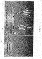
- FIG. 4 illustrates the operation of the dual frequency planar array transducer in a current profiling application where the dual frequency planar array transducer can operate from either a mobile surface vessel 410 or alternatively from a fixed (e.g. moored) location 420.
- the mobile surface vessels with the dual frequency planar array transducer can generate current profiles 430 as a function of depth.
- Current profiles with high temporal, spatial and velocity resolution utilize the embedded high frequency 2D transducer array to measure near the surface (where there are more spatially and velocity dynamic currents), while current profiles deeper in the water column (where there are less spatially and velocity dynamic currents) are measured using the low frequency 2D transducer array.
- this single multi-frequency ADCP achieves essentially identical performance of multiple discrete single frequency ADCPs, while simplifying installation as the dual frequency ADCP can be installed in a single location on, for example, a ship's hull.
Landscapes
- Engineering & Computer Science (AREA)
- Radar, Positioning & Navigation (AREA)
- Remote Sensing (AREA)
- Physics & Mathematics (AREA)
- Computer Networks & Wireless Communication (AREA)
- General Physics & Mathematics (AREA)
- Acoustics & Sound (AREA)
- Mechanical Engineering (AREA)
- Measurement Of Velocity Or Position Using Acoustic Or Ultrasonic Waves (AREA)
- Transducers For Ultrasonic Waves (AREA)
Claims (12)
- Un réseau de transducteurs multifréquence (300) composé des éléments suivants :
une surface plate unique et essentiellement plane qui se compose des éléments suivants :un premier réseau de transducteurs (310) comportant une première pluralité d'éléments à transducteurs (302) configurés pour une première fréquence nominale et chaque unité de cette première pluralité d'éléments à transducteurs (302) a une première taille etun deuxième réseau de transducteurs (320) comportant une deuxième pluralité d'éléments à transducteurs (302) configurés pour une deuxième fréquence nominale et chaque unité de cette deuxième pluralité d'éléments à transducteurs (302) a une deuxième taille différente de la première taille et se caractérisant par le fait que le premier réseau de transducteurs (310) a, en général, un profil annulaire qui définit une partie centrale (330) qui ne contient aucune unité de la première pluralité d'éléments à transducteurs et par le fait que le deuxième réseau de transducteurs (320) est distinct, au niveau spatial, du premier réseau de transducteurs et vient se positionner à l'intérieur de la partie centrale (330). - Le réseau de transducteurs multifréquence que décrit la revendication 1, si ce n'est que le premier réseau de transducteurs (310) occupe une première partie symétrique de la surface plate unique qui est essentiellement plane alors que le deuxième réseau de transducteurs (320) occupe une deuxième partie symétrique de la surface plate unique qui est essentiellement plane.
- Le réseau de transducteurs multifréquence que décrit la revendication 2, si ce n'est que :la deuxième partie symétrique est implantée, dans sa totalité, à l'intérieur de la première partie symétrique et quela deuxième partie symétrique est essentiellement concentrique par rapport à la première partie symétrique.
- Le réseau de transducteurs multifréquence que décrit la revendication 1, si ce n'est que la première pluralité d'éléments à transducteurs (302) se compose d'un réseau qui a une rangée d'éléments à transducteurs de valeur M et une colonne d'éléments à transducteurs de valeur N.
- Le réseau de transducteurs multifréquence que décrit la revendication 4, si ce n'est que la deuxième pluralité d'éléments à transducteurs (302) se compose d'un réseau qui a une rangée d'éléments à transducteurs de valeur X et une colonne d'éléments à transducteurs de valeur Y.
- Le réseau de transducteurs multifréquence que décrit la revendication 5, si ce n'est que :la valeur M est égale à la valeur X et que la valeur N est égale à la valeur Y etque la valeur M est égale à la valeur N.
- Le réseau de transducteurs multifréquence que décrit la revendication 1, si ce n'est que :le premier réseau de transducteurs (310) est optimisé pour une exploitation à une première profondeur etque le deuxième réseau de transducteurs (320) est optimisé pour une exploitation à une deuxième profondeur et que ladite deuxième profondeur est différente de ladite première profondeur.
- Le réseau de transducteurs multifréquence que décrit la revendication 7, si ce n'est que la première profondeur devrait avoir une valeur spatiale et un courant dynamique de vitesse qui sont inférieurs à ceux de ladite deuxième profondeur.
- Le réseau de transducteurs multifréquence que décrit la revendication 8, si ce n'est que l'optimisation du premier réseau de transducteurs et du deuxième réseau de transducteurs englobe la configuration d'une fréquence d'exploitation pour, respectivement, le premier réseau de transducteurs et le deuxième réseau de transducteurs.
- Le réseau de transducteurs multifréquence que décrit la revendication 7, si ce n'est que le deuxième réseau de transducteurs (320) comporte une structure entièrement remplie de réseau alors que le premier réseau de transducteurs (310) comporte une structure partiellement remplie de réseau.
- Le réseau de transducteurs multifréquence que décrit la revendication 1, si ce n'est que la surface plate unique qui est essentiellement plane comporte au moins deux transducteurs planaires dimensionnels (310, 320) qui sont indépendants sur les plans électriques et acoustiques et si ce n'est que la surface plate unique qui est essentiellement plane est configurée pour former, simultanément ou séquentiellement, des faisceaux acoustiques multiples au niveau d'au moins deux fréquences acoustiques séparées et le long d'au moins deux axes.
- Un procédé de conduction de courant dont le profil est conçu pour produire une pluralité de profils, et ce procédé se caractérise par le fait qu'il consiste :
à utiliser un réseau de transducteurs planaires multifréquence que décrit l'une ou l'autre des revendications 1 à 11, en association avec un navire en mouvement et la deuxième fréquence nominale est plus élevée que la première fréquence nominale, et la pluralité de profils contient :au moins un premier profil de courant qui a une première résolution, et ce premier profil, au nombre d'au moins un, s'obtient en faisant appel au premier réseau de transducteursau moins un deuxième profil de courant qui a une deuxième résolution plus élevée que la première résolution, et ce deuxième profil, au nombre d'au moins un, s'obtient en faisant appel au deuxième réseau de transducteurs, et ce deuxième profil, au nombre d'au moins un, s'obtient en faisant appel au deuxième réseau de transducteurset ce deuxième profil de courant, au nombre d'au moins un, s'obtient au niveau ou à proximité de la surface d'un plan d'eau et ce premier profil de courant, au nombre d'au moins un, s'obtient essentiellement de manière simultanée par rapport au deuxième profil, au nombre d'au moins un, et à une profondeur, dans le plan d'eau, qui ne se situe pas au niveau ou à proximité de la surface, et la première résolution et la deuxième résolution se composent, individuellement, d'au moins i) une résolution temporelle, ii) une résolution spatiale et (ou) iii) une résolution de vitesse.
Applications Claiming Priority (3)
| Application Number | Priority Date | Filing Date | Title |
|---|---|---|---|
| US45608610P | 2010-11-01 | 2010-11-01 | |
| PCT/US2011/057929 WO2012061179A2 (fr) | 2010-11-01 | 2011-10-26 | Transducteur pour réseau phasé bidimensionnel multifréquence |
| US13/282,257 US10054681B2 (en) | 2010-11-01 | 2011-10-26 | Multi frequency 2D phased array transducer |
Publications (3)
| Publication Number | Publication Date |
|---|---|
| EP2636150A2 EP2636150A2 (fr) | 2013-09-11 |
| EP2636150A4 EP2636150A4 (fr) | 2015-06-24 |
| EP2636150B1 true EP2636150B1 (fr) | 2020-07-15 |
Family
ID=45996656
Family Applications (1)
| Application Number | Title | Priority Date | Filing Date |
|---|---|---|---|
| EP11838559.0A Active EP2636150B1 (fr) | 2010-11-01 | 2011-10-26 | Transducteur pour réseau phasé bidimensionnel multifréquence |
Country Status (4)
| Country | Link |
|---|---|
| US (2) | US10054681B2 (fr) |
| EP (1) | EP2636150B1 (fr) |
| CN (1) | CN103650352B (fr) |
| WO (1) | WO2012061179A2 (fr) |
Families Citing this family (22)
| Publication number | Priority date | Publication date | Assignee | Title |
|---|---|---|---|---|
| EP2636150B1 (fr) | 2010-11-01 | 2020-07-15 | Rowe Technologies, Inc. | Transducteur pour réseau phasé bidimensionnel multifréquence |
| EP2673656B1 (fr) * | 2011-02-09 | 2021-03-31 | Raytheon Company | Système d'ensemble adaptatif électroniquement orientable (aesa) pour un fonctionnement multibandes et multiouvertures et procédé de conservation de liaisons de données avec une ou plusieurs stations dans différentes bandes de fréquences |
| US9823104B2 (en) | 2013-02-21 | 2017-11-21 | Rowe Technologies, Inc. | Acquatic velocity scanning apparatus and methods |
| US10247822B2 (en) | 2013-03-14 | 2019-04-02 | Navico Holding As | Sonar transducer assembly |
| US20140259618A1 (en) * | 2013-03-15 | 2014-09-18 | Hadal, Inc. | Systems and methods for improved pressure vessels |
| HK1224380A1 (zh) * | 2013-08-15 | 2017-08-18 | 罗韦技术有限公司 | 子阵列换能器设备及方法 |
| US10597130B2 (en) | 2015-01-15 | 2020-03-24 | Navico Holding As | Trolling motor with a transducer array |
| US11209543B2 (en) | 2015-01-15 | 2021-12-28 | Navico Holding As | Sonar transducer having electromagnetic shielding |
| US9784832B2 (en) * | 2015-03-05 | 2017-10-10 | Navico Holding As | Systems and associated methods for producing a 3D sonar image |
| CN105004880B (zh) * | 2015-07-06 | 2017-12-29 | 杭州开闳环境科技有限公司 | 一种采用高次谐波分量的adcp流速测速系统 |
| US10132924B2 (en) * | 2016-04-29 | 2018-11-20 | R2Sonic, Llc | Multimission and multispectral sonar |
| FR3051693B1 (fr) * | 2016-05-31 | 2018-05-11 | Imasonic | Reseau d'elements transducteurs ultrasonores |
| US10719077B2 (en) | 2016-10-13 | 2020-07-21 | Navico Holding As | Castable sonar devices and operations in a marine environment |
| US11143758B2 (en) | 2017-10-13 | 2021-10-12 | Navico Holding As | Sonar transducer performance optimization |
| CN108226911B (zh) * | 2017-12-27 | 2021-09-28 | 南京世海声学科技有限公司 | 一种具有环境适应性的adcp发射频率优化选取方法 |
| US20190257930A1 (en) * | 2018-02-21 | 2019-08-22 | Rowe Technologies, Inc. | Multi frequency piston transducer |
| CN109211340A (zh) * | 2018-08-30 | 2019-01-15 | 中国船舶重工集团公司第七〇五研究所 | 一种大尺寸深水换能器基阵设计制造结构及方法 |
| EP3861371A4 (fr) * | 2018-10-01 | 2022-04-13 | Teledyne Instruments, Inc. | Réseau à commande de phase à double fréquence acoustique à angles de faisceau communs |
| CN110749343A (zh) * | 2019-09-29 | 2020-02-04 | 杭州电子科技大学 | 基于六边形网格布局的多频带mems超声换能器阵列 |
| CN112691876A (zh) * | 2020-11-24 | 2021-04-23 | 海鹰企业集团有限责任公司 | 一种低旁瓣线阵换能器及降低旁瓣权系数的方法 |
| WO2023240044A1 (fr) * | 2022-06-06 | 2023-12-14 | Teledyne Instruments, Inc. | Transducteur avec systèmes et procédés de précision d'estimation de vitesse améliorée |
| FR3153407A1 (fr) | 2023-09-25 | 2025-03-28 | Farès Abda | Systèmes et procédés de mesures par effet doppler à l’aide d’une architecture hexagonale optimale à géométrie fixe ou adaptative |
Family Cites Families (49)
| Publication number | Priority date | Publication date | Assignee | Title |
|---|---|---|---|---|
| US3953828A (en) | 1968-11-08 | 1976-04-27 | The United States Of America As Represented By The Secretary Of The Navy | High power-wide frequency band electroacoustic transducer |
| US3587561A (en) | 1969-06-05 | 1971-06-28 | Hoffmann La Roche | Ultrasonic transducer assembly for biological monitoring |
| FR2302655A1 (fr) | 1975-02-27 | 1976-09-24 | France Etat | Transducteur piezoelectrique multimoteurs a contremasse unique |
| DE3812244C1 (fr) | 1988-04-13 | 1989-11-09 | Honeywell-Elac-Nautik Gmbh, 2300 Kiel, De | |
| US5208785A (en) | 1990-09-26 | 1993-05-04 | Rowe, Deines Instruments Incorporated | Broadband acoustic doppler current profiler |
| JP2695989B2 (ja) | 1990-09-26 | 1998-01-14 | ロウ,デインズ インストルメント インコーポレイテッド | 速度測定システム及びトップラーソナーシステム及びソナー |
| US5343443A (en) | 1990-10-15 | 1994-08-30 | Rowe, Deines Instruments, Inc. | Broadband acoustic transducer |
| US5077700A (en) * | 1990-12-21 | 1991-12-31 | The United States Of America As Represented By The Secretary Of The Navy | Doppler velocity profiler |
| US5122990A (en) | 1991-02-01 | 1992-06-16 | Rowe-Deines Instruments Incorporated | Bottom tracking system |
| FR2709556B1 (fr) | 1993-08-30 | 1995-11-10 | Remtech | Procédé de détermination à distance de la vitesse tridimensionnelle d'un fluide tel que l'air ou l'eau. |
| US5617865A (en) | 1995-03-31 | 1997-04-08 | Siemens Medical Systems, Inc. | Multi-dimensional ultrasonic array interconnect |
| US5689445A (en) | 1996-04-05 | 1997-11-18 | Rowe-Deines Instruments Incorporated | Electronic compass and attitude sensing system |
| US5808967A (en) * | 1996-10-07 | 1998-09-15 | Rowe-Deines Instruments Incorporated | Two-dimensional array transducer and beamformer |
| US5923617A (en) | 1997-02-05 | 1999-07-13 | The United States Of America As Represented By The Secretary Of The Navy | Frequency-steered acoustic beam forming system and process |
| US6982431B2 (en) | 1998-08-31 | 2006-01-03 | Molecular Devices Corporation | Sample analysis systems |
| US6097671A (en) | 1998-05-21 | 2000-08-01 | Rowe-Deines Instruments | Pinwheel transducer array |
| US6052334A (en) | 1998-08-04 | 2000-04-18 | Rowe-Deines Instruments | System and method for measuring wave directional spectrum and wave height |
| US6183419B1 (en) | 1999-02-01 | 2001-02-06 | General Electric Company | Multiplexed array transducers with improved far-field performance |
| US6647804B1 (en) | 1999-02-10 | 2003-11-18 | Rd Instruments, Inc. | System and method for flow measurement in a pipe |
| US20020126577A1 (en) | 2001-01-25 | 2002-09-12 | Dynamics Technology, Inc. | Multibeam synthetic aperture sonar |
| WO2003001231A2 (fr) | 2001-06-21 | 2003-01-03 | Farsounder, Inc. | Procede, appareil et systeme d'imagerie interferometrique |
| US6678210B2 (en) | 2001-08-28 | 2004-01-13 | Rowe-Deines Instruments, Inc. | Frequency division beamforming for sonar arrays |
| US6714482B2 (en) * | 2001-08-28 | 2004-03-30 | Rd Instruments, Inc. | Acoustic doppler channel flow measurement system |
| US20100255603A9 (en) | 2002-09-12 | 2010-10-07 | Putnam Martin A | Method and apparatus for aligning microbeads in order to interrogate the same |
| WO2004032747A1 (fr) | 2002-10-09 | 2004-04-22 | Matsushita Electric Industrial Co., Ltd. | Dispositif de diagnostic a ultrasons |
| US6821251B2 (en) | 2002-12-18 | 2004-11-23 | Aloka Co., Ltd. | Multiplexer for connecting a multi-row ultrasound transducer array to a beamformer |
| US7527592B2 (en) | 2003-11-21 | 2009-05-05 | General Electric Company | Ultrasound probe sub-aperture processing |
| KR20060121277A (ko) | 2003-12-30 | 2006-11-28 | 리포소닉스 인코포레이티드 | 컴포넌트 초음파 트랜스듀서 |
| US7007555B2 (en) * | 2004-03-15 | 2006-03-07 | Teledyne Rd Instruments, Inc. | System and method of horizontal wave measurement |
| US8182428B2 (en) | 2005-07-26 | 2012-05-22 | Surf Technology As | Dual frequency band ultrasound transducer arrays |
| US7542374B2 (en) * | 2006-09-28 | 2009-06-02 | Teledyne Rd Instruments, Inc. | System and method for acoustic Doppler velocity processing with a phased array transducer including applying correction factors to velocities orthogonal to the transducer face |
| US7839720B2 (en) | 2006-09-28 | 2010-11-23 | Teledyne Rd Instruments, Inc. | System and method for acoustic doppler velocity processing with a phased array transducer including using differently coded transmit pulses in each beam so that the cross-coupled side lobe error is removed |
| US8335131B2 (en) | 2006-09-29 | 2012-12-18 | Undersea Sensor Systems, Inc. | Acoustic transducer array element having a plurality of acoustically coupled transducer assemblies |
| US8009513B2 (en) * | 2006-11-06 | 2011-08-30 | Second Wind Systems, Inc. | Transducer array arrangement and operation for sodar application |
| US7911880B2 (en) | 2007-05-22 | 2011-03-22 | Nortek As | Acoustic doppler dual current profiler system and method |
| US7847925B2 (en) | 2007-06-18 | 2010-12-07 | Teledyne Rd Instruments, Inc. | System and method of acoustic doppler beamforming |
| US7889601B2 (en) | 2007-06-19 | 2011-02-15 | Lockheed Martin Corporation | Lightweight acoustic array |
| US9382063B2 (en) | 2008-04-24 | 2016-07-05 | Tconcept Company S.P.R.L. | Capsule, device, and method for preparing infused beverages |
| US9315663B2 (en) | 2008-09-26 | 2016-04-19 | Mikro Systems, Inc. | Systems, devices, and/or methods for manufacturing castings |
| US8254208B2 (en) | 2008-12-08 | 2012-08-28 | Teledyne Rd Instruments, Inc. | Multi-state beamforming array |
| US8780672B2 (en) * | 2008-12-19 | 2014-07-15 | Ysi Incorporated | Multi-frequency, multi-beam acoustic doppler system with concurrent processing |
| US8411530B2 (en) * | 2008-12-19 | 2013-04-02 | Ysi Incorporated | Multi-frequency, multi-beam acoustic doppler system |
| US8378557B2 (en) | 2010-07-09 | 2013-02-19 | General Electric Company | Thermal transfer and acoustic matching layers for ultrasound transducer |
| EP2636150B1 (fr) | 2010-11-01 | 2020-07-15 | Rowe Technologies, Inc. | Transducteur pour réseau phasé bidimensionnel multifréquence |
| GB2486680A (en) | 2010-12-22 | 2012-06-27 | Morgan Electro Ceramics Ltd | Ultrasonic or acoustic transducer that supports two or more frequencies |
| EP2691996A4 (fr) | 2011-03-30 | 2015-01-28 | Ambature Inc | Dispositifs électriques, mécaniques, informatiques, et/ou autres dispositifs constitués de matériaux à résistance extrêmement faible |
| US9823104B2 (en) * | 2013-02-21 | 2017-11-21 | Rowe Technologies, Inc. | Acquatic velocity scanning apparatus and methods |
| HK1224380A1 (zh) * | 2013-08-15 | 2017-08-18 | 罗韦技术有限公司 | 子阵列换能器设备及方法 |
| US20190257930A1 (en) * | 2018-02-21 | 2019-08-22 | Rowe Technologies, Inc. | Multi frequency piston transducer |
-
2011
- 2011-10-26 EP EP11838559.0A patent/EP2636150B1/fr active Active
- 2011-10-26 WO PCT/US2011/057929 patent/WO2012061179A2/fr not_active Ceased
- 2011-10-26 US US13/282,257 patent/US10054681B2/en not_active Expired - Fee Related
- 2011-10-26 CN CN201180058392.1A patent/CN103650352B/zh not_active Expired - Fee Related
-
2018
- 2018-08-20 US US16/105,487 patent/US10698107B2/en not_active Expired - Fee Related
Non-Patent Citations (1)
| Title |
|---|
| None * |
Also Published As
| Publication number | Publication date |
|---|---|
| US10698107B2 (en) | 2020-06-30 |
| US20120106299A1 (en) | 2012-05-03 |
| EP2636150A4 (fr) | 2015-06-24 |
| US10054681B2 (en) | 2018-08-21 |
| EP2636150A2 (fr) | 2013-09-11 |
| WO2012061179A2 (fr) | 2012-05-10 |
| US20190086538A1 (en) | 2019-03-21 |
| CN103650352B (zh) | 2020-03-06 |
| WO2012061179A8 (fr) | 2012-09-20 |
| WO2012061179A3 (fr) | 2014-04-10 |
| CN103650352A (zh) | 2014-03-19 |
Similar Documents
| Publication | Publication Date | Title |
|---|---|---|
| EP2636150B1 (fr) | Transducteur pour réseau phasé bidimensionnel multifréquence | |
| US10260920B2 (en) | Acquatic velocity scanning apparatus and methods | |
| US7847925B2 (en) | System and method of acoustic doppler beamforming | |
| EP0929825B1 (fr) | Transducteur de reseau bidimensionnel et formeur de faisceau | |
| EP2074433B1 (fr) | Systeme et procede pour le traitement de la vitesse doppler acoustique avec un transducteur a commande de phase | |
| US11333757B2 (en) | Acoustic phased array with reduced beam angle | |
| US11726196B2 (en) | Sonar system with increased transverse beam width | |
| WO2008105932A2 (fr) | Système et procédé pour sonar frontal | |
| US7539082B2 (en) | System and method for acoustic Doppler velocity processing with a phased array transducer including using a wide bandwidth pulse transmission to resolve ambiguity in a narrow bandwidth velocity estimate | |
| US20190257930A1 (en) | Multi frequency piston transducer | |
| CN116888493A (zh) | 多输入多转向输出(mimso)雷达 | |
| Cox et al. | Performance of line arrays of vector and higher order sensors | |
| JP7238516B2 (ja) | ソーナー装置とこれを用いた目標探知方法 | |
| Blomberg et al. | Adaptive beamforming applied to a cylindrical sonar array using an interpolated array transformation | |
| US7675819B2 (en) | Volumetric passive sonobuoy array of polyvinylidene fluoride (PVDF) wires | |
| Josserand et al. | A miniature high resolution 3-D imaging sonar | |
| JP7434809B2 (ja) | ソーナー装置、方法、及びプログラム | |
| US6240050B1 (en) | Method of resetting sonar images using secondary antenna | |
| Hughes et al. | Spatially-phased transducer to form steered beams | |
| Huang et al. | The design of sidelobe suppressed PVDF beamforming elements for high performance underwater multi-beam swath transducers | |
| Becker et al. | Antenna design and performance assessment for fast high resolution sonar imaging using high bandwidth transducers and frequency domain compounding | |
| JP2010151720A (ja) | 送受波器、ラインアレイアンテナ、及びファンビーム生成方法 | |
| HK40011517A (en) | Acoustic phased array with reduced beam angle | |
| Ramsdale et al. | Effect of element failure and random errors in amplitude and phase on the sidelobe level attainable with a linear array | |
| GB2572475A (en) | Acoustic phased array with reduced beam angle |
Legal Events
| Date | Code | Title | Description |
|---|---|---|---|
| PUAI | Public reference made under article 153(3) epc to a published international application that has entered the european phase |
Free format text: ORIGINAL CODE: 0009012 |
|
| 17P | Request for examination filed |
Effective date: 20130429 |
|
| AK | Designated contracting states |
Kind code of ref document: A2 Designated state(s): AL AT BE BG CH CY CZ DE DK EE ES FI FR GB GR HR HU IE IS IT LI LT LU LV MC MK MT NL NO PL PT RO RS SE SI SK SM TR |
|
| DAX | Request for extension of the european patent (deleted) | ||
| R17D | Deferred search report published (corrected) |
Effective date: 20140410 |
|
| RIN1 | Information on inventor provided before grant (corrected) |
Inventor name: ROWE, FRANCIS, DALE Inventor name: ROMEO, JOHN Inventor name: KRAEUTNER, PAUL |
|
| A4 | Supplementary search report drawn up and despatched |
Effective date: 20150521 |
|
| RIC1 | Information provided on ipc code assigned before grant |
Ipc: G01S 15/89 20060101ALI20150515BHEP Ipc: H04R 1/40 20060101ALI20150515BHEP Ipc: B06B 1/06 20060101ALI20150515BHEP Ipc: G01S 7/52 20060101AFI20150515BHEP Ipc: G01S 15/58 20060101ALI20150515BHEP Ipc: G01S 15/60 20060101ALI20150515BHEP |
|
| STAA | Information on the status of an ep patent application or granted ep patent |
Free format text: STATUS: EXAMINATION IS IN PROGRESS |
|
| 17Q | First examination report despatched |
Effective date: 20171115 |
|
| RIN1 | Information on inventor provided before grant (corrected) |
Inventor name: ROMEO, JOHN Inventor name: ROWE, FRANCIS, DALE |
|
| GRAP | Despatch of communication of intention to grant a patent |
Free format text: ORIGINAL CODE: EPIDOSNIGR1 |
|
| STAA | Information on the status of an ep patent application or granted ep patent |
Free format text: STATUS: GRANT OF PATENT IS INTENDED |
|
| INTG | Intention to grant announced |
Effective date: 20200205 |
|
| GRAS | Grant fee paid |
Free format text: ORIGINAL CODE: EPIDOSNIGR3 |
|
| GRAA | (expected) grant |
Free format text: ORIGINAL CODE: 0009210 |
|
| STAA | Information on the status of an ep patent application or granted ep patent |
Free format text: STATUS: THE PATENT HAS BEEN GRANTED |
|
| AK | Designated contracting states |
Kind code of ref document: B1 Designated state(s): AL AT BE BG CH CY CZ DE DK EE ES FI FR GB GR HR HU IE IS IT LI LT LU LV MC MK MT NL NO PL PT RO RS SE SI SK SM TR |
|
| REG | Reference to a national code |
Ref country code: CH Ref legal event code: EP Ref country code: GB Ref legal event code: FG4D |
|
| REG | Reference to a national code |
Ref country code: DE Ref legal event code: R096 Ref document number: 602011067819 Country of ref document: DE |
|
| REG | Reference to a national code |
Ref country code: IE Ref legal event code: FG4D |
|
| REG | Reference to a national code |
Ref country code: AT Ref legal event code: REF Ref document number: 1291629 Country of ref document: AT Kind code of ref document: T Effective date: 20200815 |
|
| REG | Reference to a national code |
Ref country code: NO Ref legal event code: T2 Effective date: 20200715 |
|
| REG | Reference to a national code |
Ref country code: LT Ref legal event code: MG4D |
|
| REG | Reference to a national code |
Ref country code: AT Ref legal event code: MK05 Ref document number: 1291629 Country of ref document: AT Kind code of ref document: T Effective date: 20200715 |
|
| REG | Reference to a national code |
Ref country code: NL Ref legal event code: MP Effective date: 20200715 |
|
| PG25 | Lapsed in a contracting state [announced via postgrant information from national office to epo] |
Ref country code: FI Free format text: LAPSE BECAUSE OF FAILURE TO SUBMIT A TRANSLATION OF THE DESCRIPTION OR TO PAY THE FEE WITHIN THE PRESCRIBED TIME-LIMIT Effective date: 20200715 Ref country code: HR Free format text: LAPSE BECAUSE OF FAILURE TO SUBMIT A TRANSLATION OF THE DESCRIPTION OR TO PAY THE FEE WITHIN THE PRESCRIBED TIME-LIMIT Effective date: 20200715 Ref country code: AT Free format text: LAPSE BECAUSE OF FAILURE TO SUBMIT A TRANSLATION OF THE DESCRIPTION OR TO PAY THE FEE WITHIN THE PRESCRIBED TIME-LIMIT Effective date: 20200715 Ref country code: LT Free format text: LAPSE BECAUSE OF FAILURE TO SUBMIT A TRANSLATION OF THE DESCRIPTION OR TO PAY THE FEE WITHIN THE PRESCRIBED TIME-LIMIT Effective date: 20200715 Ref country code: PT Free format text: LAPSE BECAUSE OF FAILURE TO SUBMIT A TRANSLATION OF THE DESCRIPTION OR TO PAY THE FEE WITHIN THE PRESCRIBED TIME-LIMIT Effective date: 20201116 Ref country code: BG Free format text: LAPSE BECAUSE OF FAILURE TO SUBMIT A TRANSLATION OF THE DESCRIPTION OR TO PAY THE FEE WITHIN THE PRESCRIBED TIME-LIMIT Effective date: 20201015 Ref country code: GR Free format text: LAPSE BECAUSE OF FAILURE TO SUBMIT A TRANSLATION OF THE DESCRIPTION OR TO PAY THE FEE WITHIN THE PRESCRIBED TIME-LIMIT Effective date: 20201016 Ref country code: ES Free format text: LAPSE BECAUSE OF FAILURE TO SUBMIT A TRANSLATION OF THE DESCRIPTION OR TO PAY THE FEE WITHIN THE PRESCRIBED TIME-LIMIT Effective date: 20200715 Ref country code: SE Free format text: LAPSE BECAUSE OF FAILURE TO SUBMIT A TRANSLATION OF THE DESCRIPTION OR TO PAY THE FEE WITHIN THE PRESCRIBED TIME-LIMIT Effective date: 20200715 |
|
| PG25 | Lapsed in a contracting state [announced via postgrant information from national office to epo] |
Ref country code: PL Free format text: LAPSE BECAUSE OF FAILURE TO SUBMIT A TRANSLATION OF THE DESCRIPTION OR TO PAY THE FEE WITHIN THE PRESCRIBED TIME-LIMIT Effective date: 20200715 Ref country code: LV Free format text: LAPSE BECAUSE OF FAILURE TO SUBMIT A TRANSLATION OF THE DESCRIPTION OR TO PAY THE FEE WITHIN THE PRESCRIBED TIME-LIMIT Effective date: 20200715 Ref country code: RS Free format text: LAPSE BECAUSE OF FAILURE TO SUBMIT A TRANSLATION OF THE DESCRIPTION OR TO PAY THE FEE WITHIN THE PRESCRIBED TIME-LIMIT Effective date: 20200715 Ref country code: IS Free format text: LAPSE BECAUSE OF FAILURE TO SUBMIT A TRANSLATION OF THE DESCRIPTION OR TO PAY THE FEE WITHIN THE PRESCRIBED TIME-LIMIT Effective date: 20201115 |
|
| PG25 | Lapsed in a contracting state [announced via postgrant information from national office to epo] |
Ref country code: NL Free format text: LAPSE BECAUSE OF FAILURE TO SUBMIT A TRANSLATION OF THE DESCRIPTION OR TO PAY THE FEE WITHIN THE PRESCRIBED TIME-LIMIT Effective date: 20200715 |
|
| REG | Reference to a national code |
Ref country code: DE Ref legal event code: R097 Ref document number: 602011067819 Country of ref document: DE |
|
| PG25 | Lapsed in a contracting state [announced via postgrant information from national office to epo] |
Ref country code: IT Free format text: LAPSE BECAUSE OF FAILURE TO SUBMIT A TRANSLATION OF THE DESCRIPTION OR TO PAY THE FEE WITHIN THE PRESCRIBED TIME-LIMIT Effective date: 20200715 Ref country code: EE Free format text: LAPSE BECAUSE OF FAILURE TO SUBMIT A TRANSLATION OF THE DESCRIPTION OR TO PAY THE FEE WITHIN THE PRESCRIBED TIME-LIMIT Effective date: 20200715 Ref country code: CZ Free format text: LAPSE BECAUSE OF FAILURE TO SUBMIT A TRANSLATION OF THE DESCRIPTION OR TO PAY THE FEE WITHIN THE PRESCRIBED TIME-LIMIT Effective date: 20200715 Ref country code: DK Free format text: LAPSE BECAUSE OF FAILURE TO SUBMIT A TRANSLATION OF THE DESCRIPTION OR TO PAY THE FEE WITHIN THE PRESCRIBED TIME-LIMIT Effective date: 20200715 Ref country code: SM Free format text: LAPSE BECAUSE OF FAILURE TO SUBMIT A TRANSLATION OF THE DESCRIPTION OR TO PAY THE FEE WITHIN THE PRESCRIBED TIME-LIMIT Effective date: 20200715 Ref country code: RO Free format text: LAPSE BECAUSE OF FAILURE TO SUBMIT A TRANSLATION OF THE DESCRIPTION OR TO PAY THE FEE WITHIN THE PRESCRIBED TIME-LIMIT Effective date: 20200715 |
|
| REG | Reference to a national code |
Ref country code: DE Ref legal event code: R119 Ref document number: 602011067819 Country of ref document: DE |
|
| PLBE | No opposition filed within time limit |
Free format text: ORIGINAL CODE: 0009261 |
|
| STAA | Information on the status of an ep patent application or granted ep patent |
Free format text: STATUS: NO OPPOSITION FILED WITHIN TIME LIMIT |
|
| REG | Reference to a national code |
Ref country code: NO Ref legal event code: MMEP |
|
| PG25 | Lapsed in a contracting state [announced via postgrant information from national office to epo] |
Ref country code: AL Free format text: LAPSE BECAUSE OF FAILURE TO SUBMIT A TRANSLATION OF THE DESCRIPTION OR TO PAY THE FEE WITHIN THE PRESCRIBED TIME-LIMIT Effective date: 20200715 |
|
| REG | Reference to a national code |
Ref country code: CH Ref legal event code: PL |
|
| 26N | No opposition filed |
Effective date: 20210416 |
|
| GBPC | Gb: european patent ceased through non-payment of renewal fee |
Effective date: 20201026 |
|
| PG25 | Lapsed in a contracting state [announced via postgrant information from national office to epo] |
Ref country code: LU Free format text: LAPSE BECAUSE OF NON-PAYMENT OF DUE FEES Effective date: 20201026 Ref country code: MC Free format text: LAPSE BECAUSE OF FAILURE TO SUBMIT A TRANSLATION OF THE DESCRIPTION OR TO PAY THE FEE WITHIN THE PRESCRIBED TIME-LIMIT Effective date: 20200715 Ref country code: SK Free format text: LAPSE BECAUSE OF FAILURE TO SUBMIT A TRANSLATION OF THE DESCRIPTION OR TO PAY THE FEE WITHIN THE PRESCRIBED TIME-LIMIT Effective date: 20200715 |
|
| REG | Reference to a national code |
Ref country code: BE Ref legal event code: MM Effective date: 20201031 |
|
| PG25 | Lapsed in a contracting state [announced via postgrant information from national office to epo] |
Ref country code: NO Free format text: LAPSE BECAUSE OF NON-PAYMENT OF DUE FEES Effective date: 20201031 Ref country code: DE Free format text: LAPSE BECAUSE OF NON-PAYMENT OF DUE FEES Effective date: 20210501 Ref country code: FR Free format text: LAPSE BECAUSE OF NON-PAYMENT OF DUE FEES Effective date: 20201031 |
|
| PG25 | Lapsed in a contracting state [announced via postgrant information from national office to epo] |
Ref country code: GB Free format text: LAPSE BECAUSE OF NON-PAYMENT OF DUE FEES Effective date: 20201026 Ref country code: LI Free format text: LAPSE BECAUSE OF NON-PAYMENT OF DUE FEES Effective date: 20201031 Ref country code: SI Free format text: LAPSE BECAUSE OF FAILURE TO SUBMIT A TRANSLATION OF THE DESCRIPTION OR TO PAY THE FEE WITHIN THE PRESCRIBED TIME-LIMIT Effective date: 20200715 Ref country code: BE Free format text: LAPSE BECAUSE OF NON-PAYMENT OF DUE FEES Effective date: 20201031 Ref country code: CH Free format text: LAPSE BECAUSE OF NON-PAYMENT OF DUE FEES Effective date: 20201031 |
|
| PG25 | Lapsed in a contracting state [announced via postgrant information from national office to epo] |
Ref country code: IE Free format text: LAPSE BECAUSE OF NON-PAYMENT OF DUE FEES Effective date: 20201026 |
|
| PG25 | Lapsed in a contracting state [announced via postgrant information from national office to epo] |
Ref country code: TR Free format text: LAPSE BECAUSE OF FAILURE TO SUBMIT A TRANSLATION OF THE DESCRIPTION OR TO PAY THE FEE WITHIN THE PRESCRIBED TIME-LIMIT Effective date: 20200715 Ref country code: MT Free format text: LAPSE BECAUSE OF FAILURE TO SUBMIT A TRANSLATION OF THE DESCRIPTION OR TO PAY THE FEE WITHIN THE PRESCRIBED TIME-LIMIT Effective date: 20200715 Ref country code: CY Free format text: LAPSE BECAUSE OF FAILURE TO SUBMIT A TRANSLATION OF THE DESCRIPTION OR TO PAY THE FEE WITHIN THE PRESCRIBED TIME-LIMIT Effective date: 20200715 |
|
| PG25 | Lapsed in a contracting state [announced via postgrant information from national office to epo] |
Ref country code: MK Free format text: LAPSE BECAUSE OF FAILURE TO SUBMIT A TRANSLATION OF THE DESCRIPTION OR TO PAY THE FEE WITHIN THE PRESCRIBED TIME-LIMIT Effective date: 20200715 |