EP2636367B1 - Pet-mrt-vorrichtung - Google Patents
Pet-mrt-vorrichtung Download PDFInfo
- Publication number
- EP2636367B1 EP2636367B1 EP11837955.1A EP11837955A EP2636367B1 EP 2636367 B1 EP2636367 B1 EP 2636367B1 EP 11837955 A EP11837955 A EP 11837955A EP 2636367 B1 EP2636367 B1 EP 2636367B1
- Authority
- EP
- European Patent Office
- Prior art keywords
- pet
- detectors
- image
- magnetic field
- mri apparatus
- Prior art date
- Legal status (The legal status is an assumption and is not a legal conclusion. Google has not performed a legal analysis and makes no representation as to the accuracy of the status listed.)
- Active
Links
Images




Classifications
-
- G—PHYSICS
- G01—MEASURING; TESTING
- G01R—MEASURING ELECTRIC VARIABLES; MEASURING MAGNETIC VARIABLES
- G01R33/00—Arrangements or instruments for measuring magnetic variables
- G01R33/20—Arrangements or instruments for measuring magnetic variables involving magnetic resonance
- G01R33/28—Details of apparatus provided for in groups G01R33/44 - G01R33/64
-
- A—HUMAN NECESSITIES
- A61—MEDICAL OR VETERINARY SCIENCE; HYGIENE
- A61B—DIAGNOSIS; SURGERY; IDENTIFICATION
- A61B6/00—Apparatus or devices for radiation diagnosis; Apparatus or devices for radiation diagnosis combined with radiation therapy equipment
- A61B6/02—Arrangements for diagnosis sequentially in different planes; Stereoscopic radiation diagnosis
- A61B6/03—Computed tomography [CT]
- A61B6/037—Emission tomography
-
- A—HUMAN NECESSITIES
- A61—MEDICAL OR VETERINARY SCIENCE; HYGIENE
- A61B—DIAGNOSIS; SURGERY; IDENTIFICATION
- A61B6/00—Apparatus or devices for radiation diagnosis; Apparatus or devices for radiation diagnosis combined with radiation therapy equipment
- A61B6/44—Constructional features of apparatus for radiation diagnosis
- A61B6/4417—Constructional features of apparatus for radiation diagnosis related to combined acquisition of different diagnostic modalities
-
- G—PHYSICS
- G01—MEASURING; TESTING
- G01R—MEASURING ELECTRIC VARIABLES; MEASURING MAGNETIC VARIABLES
- G01R33/00—Arrangements or instruments for measuring magnetic variables
- G01R33/20—Arrangements or instruments for measuring magnetic variables involving magnetic resonance
- G01R33/44—Arrangements or instruments for measuring magnetic variables involving magnetic resonance using nuclear magnetic resonance [NMR]
- G01R33/48—NMR imaging systems
- G01R33/4808—Multimodal MR, e.g. MR combined with positron emission tomography [PET], MR combined with ultrasound or MR combined with computed tomography [CT]
- G01R33/481—MR combined with positron emission tomography [PET] or single photon emission computed tomography [SPECT]
-
- G—PHYSICS
- G01—MEASURING; TESTING
- G01T—MEASUREMENT OF NUCLEAR OR X-RADIATION
- G01T1/00—Measuring X-radiation, gamma radiation, corpuscular radiation, or cosmic radiation
- G01T1/16—Measuring radiation intensity
- G01T1/1603—Measuring radiation intensity with a combination of at least two different types of detectors
-
- A—HUMAN NECESSITIES
- A61—MEDICAL OR VETERINARY SCIENCE; HYGIENE
- A61B—DIAGNOSIS; SURGERY; IDENTIFICATION
- A61B5/00—Measuring for diagnostic purposes; Identification of persons
- A61B5/0033—Features or image-related aspects of imaging apparatus, e.g. for MRI, optical tomography or impedance tomography apparatus; Arrangements of imaging apparatus in a room
- A61B5/0035—Features or image-related aspects of imaging apparatus, e.g. for MRI, optical tomography or impedance tomography apparatus; Arrangements of imaging apparatus in a room adapted for acquisition of images from more than one imaging mode, e.g. combining MRI and optical tomography
-
- A—HUMAN NECESSITIES
- A61—MEDICAL OR VETERINARY SCIENCE; HYGIENE
- A61B—DIAGNOSIS; SURGERY; IDENTIFICATION
- A61B5/00—Measuring for diagnostic purposes; Identification of persons
- A61B5/05—Detecting, measuring or recording for diagnosis by means of electric currents or magnetic fields; Measuring using microwaves or radio waves
- A61B5/055—Detecting, measuring or recording for diagnosis by means of electric currents or magnetic fields; Measuring using microwaves or radio waves involving electronic [EMR] or nuclear [NMR] magnetic resonance, e.g. magnetic resonance imaging
Definitions
- Embodiments described herein relate generally to a PET (Positron Emission Tomography)-MRI (Magnetic Resonance Imaging) apparatus.
- MRI apparatuses have been utilized to inspect cephalic regions, for example. It has been also expected that PET apparatuses are utilized to inspect cephalic regions, e.g., to diagnose Alzheimer diseases. Hence, recently, it has been expected to realize a PET-MRI apparatus combining a PET apparatus and an MRI apparatus.
- MRI apparatuses have some limitations.
- a photomultiplier tube (PMT) used as a detector of a conventional PET apparatus cannot be used when the PET-MRI apparatus is intended to be realized because a strong radio frequency magnetic field is used in the MRI apparatus. Therefore, a PET-MRI apparatus has been proposed that uses an APD (Avalanche Photodiode) element or a SiPM (Silicon Photomultiplier) instead of the PMT, for example.
- APD Anavalanche Photodiode
- SiPM Silicon Photomultiplier
- a PET detector is disposed at the magnetic field center included in an effective imaging region of MR images. Such a disposition is the most suitable for taking PET images. However, in order to take MR images, this disposition is not always the most suitable because MR images having sufficient image quality are not obtained in some cases due to influence of material of the PET detector disposed around the magnetic field center.
- WO 2009/107005 relates to an imaging system comprising: a magnetic resonance scanner having a cylindrical bore defining a cylinder axis (DA), the magnetic resonance scanner having a gradient coil (10, 10') defining an isocenter within the bore and an isoplane passing through the isocenter and oriented transverse to the cylinder axis; a ring of radiation detectors arranged concentric with the cylindrical bore and configured to detect radiation emanating from within the bore; and a generally annular electronic circuit board arranged concentric with the cylindrical bore and centered on the isoplane, the generally annular electronic circuit board operatively connected with the ring of radiation detectors to generate electrical signals indicative of detection of radiation by the ring of radiation detectors.
- DA cylinder axis
- US 7 667 457 relates to a gamma ray detector ring for a combined positron emission tomography (PET) and magnetic resonance imaging (MRI) system which is integrated into a radio frequency (RF) coil assembly such that the detector ring is integrated with a RF shield.
- Each gamma ray detector in the detector ring includes a scintillator component that emits light when a gamma ray is detected and a photodetector component designed to be sensitive to the frequency of light produced by the scintillator.
- a RF shield may be integrated into a detector ring such that the RF shield is positioned between the scintillator and photodetector components of each detector, thereby saving valuable radial space within the imaging system.
- Multiple such detector rings may be located adjacent to one another to increase axial coverage and enable three-dimensional PET imaging techniques.
- a PET-MRI apparatus according to an embodiment is recited in claim 1.
- FIG. 1 is a schematic illustrating a structure of a PET-MRI apparatus 100 according to the first embodiment.
- the PET-MRI apparatus 100 includes a magnet 1, a couch 2, a gradient coil 3, a gradient coil driving circuit 4, a transmitting radio frequency coil 5, a transmitter 6, a receiving radio frequency coil 7, a receiver 8, an MR data acquisition unit 9, a computer 10, a console 11, a display 12, PET detectors 13a and 13b, signal lines 14, a PET data acquisition unit 15, a PET image reconstruction unit 16, a sequence controller 17, a PET detector power source 18, and power source cables 19.
- the bore is formed as the inner surface of a gantry having an approximately cylindrical shape and housing the magnet 1, the gradient coil 3, and the like.
- the couch 2 has a couchtop 2a on which a subject P is placed. When the subject P is imaged, the couch 2 moves the couchtop 2a into an inside of the bore, so that the subject P is moved in the static magnetic field.
- the gradient coil 3 applies gradient magnetic fields Gx, Gy, and Gz on the subject P.
- the magnetic field intensities of the gradient magnetic fields Gx, Gy, and Gz in the same direction (Z direction) as the static magnetic field change linearly in relation to the distance from the magnetic field center in the X, Y, and Z directions, respectively.
- the gradient coil 3 is formed in an approximately cylindrical shape and disposed on a side adjacent to an inner circumference of the magnet 1.
- the gradient coil driving circuit 4 drives the gradient coil 3 under control of the sequence controller 17.
- the transmitting radio frequency coil 5 applies a radio frequency magnetic field on the subject P placed in the static magnetic field based on a radio frequency pulse transmitted from the transmitter 6.
- the transmitting radio frequency coil 5 is formed in an approximately cylindrical shape and disposed on a side adjacent to an inner circumference of the gradient coil 3.
- the transmitter 6 transmits the radio frequency pulse to the transmitting radio frequency coil 5 under control of the sequence controller 17.
- the receiving radio frequency coil 7 detects a magnetic resonance signal emitted from the subject P due to the application of the radio frequency magnetic field and the gradient magnetic field on the subject P.
- the receiving radio frequency coil 7 is a surface coil disposed on a surface of the subject P corresponding to a region to be imaged.
- two receiving radio frequency coils 7 are disposed on the upper side and the lower side of the subject P.
- the receiver 8 receives the magnetic resonance signal detected by the receiving radio frequency coil 7 under control of the sequence controller 17.
- the receiver 8 transmits the received magnetic resonance signal to the MR data acquisition unit 9.
- the MR data acquisition unit 9 acquires the magnetic resonance signal sent from the receiver 8 under control of the sequence controller 17.
- the MR data acquisition unit 9 amplifies the acquired magnetic resonance signal and performs detection on the amplified signal. Thereafter, the MR data acquisition unit 9 A/D-converts the signal after the detection and sends the converted signal to the computer 10.
- the computer 10 which is controlled with the console 11, reconstructs an MR image based on the magnetic resonance signal sent from the MR data acquisition unit 9.
- the computer 10 allows the display 12 to display the reconstructed MR image.
- the PET detectors 13a and 13b detect, as counting information, gamma rays emitted from positron emitting radionuclides injected into the subject P.
- the PET detectors 13a and 13b are each formed in a ring shape and disposed on a side adjacent to an inner circumference of the transmitting radio frequency coil 5.
- the PET detectors 13a and 13b are each formed by arranging detector modules including scintillators and photo detectors in a ring shape.
- the scintillator include LYSO (Lutetium Yttrium Oxyorthosilicate), LSO (Lutetium Oxyorthosilicate), and LGSO (Lutetium Gadolinium Oxyorthosilicate).
- the photo detector is, for example, a semiconductor detector such as an APD (Avalanche Photodiode) element and a SiPM (Silicon Photomultiplier).
- the PET detectors 13a and 13b send the detected counting information to the PET data acquisition unit 15 through the signal lines 14.
- the PET data acquisition unit 15 produces simultaneous counting information under control of the sequence controller 17.
- the PET data acquisition unit 15 produces, as the simultaneous counting information, a combination of counting information of gamma rays (including annihilation radiation) that are emitted from the positron emitting radionuclides and approximately simultaneously detected by using the counting information of the gamma rays detected by the PET detectors 13a and 13b.
- the PET image reconstruction unit 16 reconstructs a PET image by using the simultaneous counting information produced by the PET data acquisition unit 15 as projection data.
- the PET image reconstructed by the PET image reconstruction unit 16 is transmitted to the computer 10 and displayed on the display 12.
- the sequence controller 17 controls the above-described elements based on various imaging sequences executed when the subject is imaged.
- the PET detector power source 18 supplies the PET detectors 13a and 13b with power to drive the photo detectors through the power source cables 19.
- FIG. 2 is a schematic illustrating the element arrangement at the periphery of the PET detectors 13a and 13b according to the first embodiment.
- a dot 20 illustrated in FIG. 2 represents the magnetic field center of the static magnetic field.
- a region 21 surrounded with the dashed line in FIG. 2 represents an effective imaging region of the MR image.
- the PET detectors 13a and 13b are disposed on a side adjacent to an inner circumference of a bore 22 in the first embodiment.
- the PET detectors 13a and 13b are disposed with a space therebetween in an axial direction of the bore 22 so as to interpose the magnetic field center 20 of the static magnetic field generated by the magnetostatic magnet 1 therebetween. That is, in the first embodiment, the PET detectors 13a and 13b are disposed so as to avoid the periphery of the magnetic field center included in the effective imaging region of the MR image. As a result, deterioration of image quality of the MR image due to the influence of the PET detectors is suppressed.
- the signal lines 14 and the power source cables 19 that are connected to the PET detectors 13a and 13b are routed so as not to pass through the periphery of the magnetic field center 20 of the static magnetic field generated by the magnet 1.
- the signal line 14 and the power source cable 19 that are connected to the PET detector 13a are combined and routed from the PET detector 13a to a side opposite the magnetic field center 20.
- the signal line 14 and the power source cable 19 that are connected to the PET detector 13b are combined and routed from the PET detector 13b to a side opposite the magnetic field center 20.
- the signal line 14 and the power source cable 19 may be combined with cables connected to the transmitting radio frequency coil 5 and routed, for example.
- the PET detectors 13a and 13b each converts a signal relating to the detected gamma rays from an analog signal to a digital signal, thereafter further converts the digital signal into an optical signal, and outputs the optical signal.
- the PET detectors 13a and 13b each may convert a signal relating to the detected gamma rays from an analog signal to a digital signal, thereafter further convert the digital signal into a radio signal, and outputs the radio signal. In this way, signals output from the PET detectors 13a and 13b are converted into optical signals or radio signals. As a result, noises caused by the digital signals can be prevented.
- the PET-MRI apparatus 100 includes a moving mechanism that moves the PET detectors 13a and 13b along the axial direction of the bore 22.
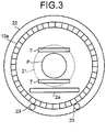
- FIG. 3 is a schematic illustrating the element arrangement at the periphery of the PET detectors 13a and 13b according to the first embodiment when viewed from the axial direction of the bore 22.
- FIG. 3 illustrates the element arrangement when the inside of the bore is viewed from an opening on a side on which the PET detector 13a is disposed.
- a moving mechanism 23 is two rails disposed on the internal surface of the bore 22 at the lower side, for example.
- the moving mechanism 23 is engaged with a rail engagement portion formed in a groove shape on the outer circumference surface of the PET detector 13a and supports the PET detector 13a so as to be movable along the axial direction of the bore 22.
- the moving mechanism 23 to move the PET detector 13b is provided on the PET detector 13b.
- the PET detectors 13a and 13b can be attachable to and detachable from the corresponding moving mechanism 23, so that they can be inserted in and removed from the bore 22 by passing through both sides of the bore 22.
- the structure allowing the PET detectors 13a and 13b to be attachable and detachable enables the PET detectors 13a and 13b to be relatively easily built in a conventional MRI apparatus, allowing the PET-MRI apparatus to be widely popularized.
- the moving mechanism 23 moves the PET detectors 13a and 13b based on imaging modes under control of the computer 10. For example, the moving mechanism 23 automatically moves the PET detectors 13a and 13b based on an imaging condition that the computer 10 receives from an operator. Alternatively, the moving mechanism 23 may move the PET detectors 13a and 13b based on a movement instruction input by an operator through the console 11.
- the moving mechanism 23 moves the PET detectors 13a and 13b to a position at which they interpose the magnetic field center 20 of the static magnetic field therebetween before imaging starts.
- the moving mechanism 23 moves the PET detectors 13a and 13b so as to be adjacent to each other before imaging starts.
- the moving mechanism 23 moves the PET detectors 13a and 13b out of the static magnetic field.
- the moving mechanism 23 moves the PET detectors 13a and 13b based on the imaging condition for taking the PET image and/or the imaging condition for taking the MR image. For example, when moving the PET detectors 13a and 13b, the moving mechanism 23 changes the distance between the PET detectors 13a and 13b after being moved based on a size of an FOV (Field Of View) set as the imaging condition for taking the MR image and a type of the receiving radio frequency coil 7.
- FOV Field Of View
- the PET-MRI apparatus 100 includes a vibration damping mechanism that fixes a position of each PET detector after the PET detectors 13a and 13b are moved to an imaging position by the moving mechanism 23 and damps vibration transmitted from the gradient coil 3 to each PET detector.
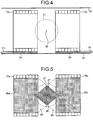
- FIG. 4 is a schematic illustrating a vibration damping mechanism 24 according to the first embodiment. As illustrated in FIG. 4 , the vibration damping mechanism 24 is disposed at an engaged portion between the PET detector 13a and the moving mechanism 23, for example. Likewise, the vibration damping mechanism 24 is disposed at an engaged portion between the PET detector 13b and the moving mechanism 23.
- FIG. 5 is a schematic illustrating the effective imaging region of the PET-MRI apparatus 100 according to the first embodiment.
- a region 25a surrounded by the inner circumference surface of the PET detector 13a and a region 25b surrounded by the inner circumference surface of the PET detector 13b are the effective imaging region in which only the PET image can be taken.
- a region 27 that is included in both of a region 26 formed between the inner circumference surface of the PET detector 13a and the inner circumference surface of the PET detector 13b and the effective imaging region 21 of the MR image is the effective imaging region in which the PET image and the MR image can be taken simultaneously.
- the effective imaging region 27 has a shape obtained by bonding the bottoms of circular cones each other.
- the effective imaging region 21 in which the MR image can be taken the effective imaging regions 25a and 25b in which the PET image can be taken, and the effective imaging region 27 in which the MR image and the PET image can be simultaneously taken are set.
- the PET-MRI apparatus 100 includes the magnetostatic magnet 1, the transmitting radio frequency coil 5, the gradient coil 3, the receiving radio frequency coil 7, the computer 10, the PET detectors 13a and 13b, and the PET image reconstruction unit 16.
- the magnetostatic magnet 1 which is the seamless structure, generates the static magnetic field in the bore 22 having a cylindrical shape.
- the transmitting radio frequency coil 5 applies the radio frequency pulse on the subject P placed in the static magnetic field.
- the gradient coil 3 applies the gradient magnetic field on the subject P on which the radio frequency pulse is applied.
- the receiving radio frequency coil 7 detects the magnetic resonance signal emitted from the subject P due to the application of the radio frequency pulse and the gradient magnetic field on the subject P.
- the computer 10 reconstructs the MR image based on the magnetic resonance signal detected by the receiving radio frequency coil 7.
- the PET detectors 13a and 13b are each formed in a ring shape and detect gamma rays emitted from positron emitting radionuclides injected into the subject P.
- the PET image reconstruction unit 16 reconstructs the PET image from projection data produced based on the gamma rays detected by the PET detectors 13a and 13b.
- the PET detectors 13a and 13b are disposed with a space therebetween in the axial direction of the bore 22 so as to interpose the magnetic field center 20 of the static magnetic field therebetween.
- the PET detectors 13a and 13b are disposed so as to avoid the periphery of the magnetic field center included in the effective imaging region of the MR image.
- deterioration of image quality of the MR image due to the influence of the PET detectors can be suppressed.
- the PET detectors 13a and 13b are disposed on the side adjacent to the inner circumference of the transmitting radio frequency coil 5.
- the PET detectors 13a and 13b can be easily added to a conventional MRI apparatus having an imaging space on the side adjacent to the inner circumference of the transmitting radio frequency coil 5, allowing the PET-MRI apparatus to be easily realized.
- the moving mechanism 23 moves the PET detectors 13a and 13b along the axial direction of the bore 22 based on the imaging modes. As a result, when both or one of the PET image and the MR image is taken, the PET detectors 13a and 13b can be moved to a proper position based on the type of imaging to be executed.
- the moving mechanism 23 moves the PET detectors 13a and 13b to the position at which they interpose the magnetic field center 20 of the static magnetic field therebetween before imaging starts.
- the moving mechanism 23 moves the PET detectors 13a and 13b so as to be adjacent to each other before imaging starts. As a result, when only the PET image is taken, a wider imaging region can be provided.
- the moving mechanism 23 moves the PET detectors 13a and 13b out of the static magnetic field.
- the MR image can be obtained that has no deterioration of image quality due to the PET detectors 13a and 13b.
- the moving mechanism 23 moves the PET detectors 13a and 13b based on the imaging condition for taking the PET image and/or the imaging condition for taking the MR image. As a result, when both or one of the PET image and the MR image is taken, the distance between the PET detectors 13a and 13b can be automatically set.
- the vibration damping mechanism 24 fixes the position of each PET detector after the PET detectors 13a and 13b are moved to the imaging position by the moving mechanism 23 and damps vibration transmitted from the gradient coil 3 to each PET detector.
- the PET detectors 13a and 13b can be protected from mechanical vibration caused by the gradient coil 3.
- the signal lines 14 and the power source cables 19 that are connected to the PET detectors 13a and 13b are routed so as not to pass through the periphery of the magnetic field center 20 of the static magnetic field. As a result, noises generated by the signals output from the PET detectors 13a and 13b can be suppressed.
- the PET detectors 13a and 13b each converts a signal relating to the detected gamma rays from an analog signal to a digital signal, thereafter further converts the digital signal into an optical signal, and outputs the optical signal.
- noises generated by the signals output from the PET detectors 13a and 13b can be more reliably suppressed.
- the PET detectors 13a and 13b each converts a signal relating to the detected gamma rays from an analog signal to a digital signal, thereafter further converts the digital signal into a radio signal, and outputs the radio signal.
- noises generated by the signals output from the PET detectors 13a and 13b can be more reliably suppressed.
- PET detectors 13a and 13b are disposed on the side adjacent to the inner circumference of the transmitting radio frequency coil 5.
- PET detectors 33a and 33b are disposed on a side adjacent to the outer circumference of the transmitting radio frequency coil 5.
- the basic structure of a PET-MRI apparatus according to the second embodiment is the same as that illustrated in FIG. 1 but only the PET detectors 33a and 33b are arranged in a different manner from those illustrated in FIG. 1 .
- FIG. 6 is a schematic illustrating the element arrangement at the periphery of the PET detectors 33a and 33b according to the second embodiment.
- the elements having the same function as the elements of FIG. 2 are labeled with the same numerals, and detailed description thereof is omitted.
- the PET detectors 33a and 33b are disposed on the side adjacent to the outer circumference of the transmitting radio frequency coil 5 in the second embodiment.
- this structure is used for imaging a body region by using the transmitting radio frequency coil 5 as a whole-body transmission RF coil and the receiving radio frequency coil 7 as a dedicated surface coil for the body region.
- the PET detectors 33a and 33b are fixedly disposed at the position so as to interpose the magnetic field center of the static magnetic field therebetween.
- the PET detectors 33a and 33b may be fixed to the apparatus with the vibration damping mechanism that damps vibration generated by the gradient coil 3 interposed therebetween in the same manner as the first embodiment.
- the PET detectors 33a and 33b are fixed to the inner circumference surface of the gradient coil 3 with the vibration damping mechanism interposed therebetween.
- the PET detectors 33a and 33b can be protected from mechanical vibration caused by the gradient coil 3 also in the second embodiment.
- the PET detectors 33a and 33b are disposed so as to avoid the periphery of the magnetic field center included in the effective imaging region of the MR image.
- deterioration of image quality of the MR image due to the influence of the PET detectors can be suppressed in the same manner as the first embodiment.
- a third embodiment is described below.
- imaging is repeated while the couchtop 2a on which the subject P is placed is moved step-by-step in the axial direction of the bore 22 in the PET-MRI apparatus described in the first or the second embodiment.
- Such an imaging method is called a step-and-shoot.
- a case is described in which the step-and-shoot is performed in the PET-MRI apparatus described in the first embodiment.
- FIG. 7 is a schematic to explain the step-and-shoot according to the third embodiment.
- the couch 2 moves the couchtop 2a, so that the subject P is moved along the axial direction of the bore 22.
- the computer 10 controls the couch 2 such that a region to be imaged of the subject P is moved step-by-step in the order of an approximate center position of the PET detector 13b, an approximate center position of a region interposed between the PET detectors 13a and 13b, and an approximate center position of the PET detector 13a.
- the receiving radio frequency coil 7 attached on the imaging position of the subject P is moved step-by-step. Specifically, the receiving radio frequency coil 7 is moved in the axial direction of the bore 22 step-by-step by a distance d that is half of the distance between the centers of the PET detectors 13a and 13b. As a result, the region to be imaged is moved in the axial direction of the bore 22 in the order of a range 41 in which only the PET image can be taken, a range 42 in which the MR image and the PET image can be taken simultaneously, and the range 41 in which only the PET image can be taken.
- the computer 10 controls the PET-MRI apparatus 100 so as to take the PET image when the region to be imaged is moved to the approximate center position of the PET detector 13a or the approximate center position of the PET detector 13b.
- the computer 10 controls the PET-MRI apparatus 100 so as to take both or one of the PET image and the MR image when the region to be imaged is moved to the approximate center position of the region interposed between the PET detectors 13a and 13b.
- the PET image and both or one of the PET image and the MR image can be taken in the order while the region to be imaged is moved step-by-step.
- the deterioration of image quality of the MR image due to the influence of the PET detectors can be suppressed in the same manner as the first and the second embodiments.
- the PET detectors 13a and 13b i.e., two PET detectors
- the embodiment of the PET-MRI apparatus is not limited to this arrangement.
- the number of PET detectors may be three or more. That is, even when more than two of the PET detectors 13a and 13b are disposed, the PET image and the MR image can be taken simultaneously in the region interposed between the PET detectors.
- the PET-MRI apparatus can be realized that can suppress the deterioration of image quality of the MR image due to the influence of the PET detectors.
Landscapes
- Health & Medical Sciences (AREA)
- Physics & Mathematics (AREA)
- Life Sciences & Earth Sciences (AREA)
- Engineering & Computer Science (AREA)
- High Energy & Nuclear Physics (AREA)
- General Health & Medical Sciences (AREA)
- Radiology & Medical Imaging (AREA)
- Medical Informatics (AREA)
- Nuclear Medicine, Radiotherapy & Molecular Imaging (AREA)
- Molecular Biology (AREA)
- General Physics & Mathematics (AREA)
- Pathology (AREA)
- Pulmonology (AREA)
- Biophysics (AREA)
- Biomedical Technology (AREA)
- Heart & Thoracic Surgery (AREA)
- Surgery (AREA)
- Animal Behavior & Ethology (AREA)
- Theoretical Computer Science (AREA)
- Public Health (AREA)
- Veterinary Medicine (AREA)
- Optics & Photonics (AREA)
- Condensed Matter Physics & Semiconductors (AREA)
- Spectroscopy & Molecular Physics (AREA)
- Nuclear Medicine (AREA)
- Magnetic Resonance Imaging Apparatus (AREA)
Claims (15)
- PET-(Positronenemissionstomografie-)MRI-(Magnetresonanztomografie-)Vorrichtung (100), umfassend:einen magnetostatischen Magneten (1), der dafür konfiguriert ist, eine nahtlose Struktur zu sein und ein statisches Magnetfeld in einem Tunnel mit zylindrischer Form zu erzeugen;eine Sende-Hochfrequenzspule (5), die dafür konfiguriert ist, einen Hochfrequenzimpuls auf einen Probanden anzuwenden, der in dem statischen Magnetfeld platziert ist;eine Gradientenspule (3), die dafür konfiguriert ist, ein Gradienten-Magnetfeld auf den Probanden anzuwenden, auf den der Hochfrequenzimpuls angewendet wird;eine Empfangs-Hochfrequenzspule (7), die dafür konfiguriert ist, ein Magnetresonanzsignal zu erfassen, das vom Probanden aufgrund der Anwendung des Hochfrequenzimpulses und des Gradienten-Magnetfeldes auf den Probanden emittiert wird;eine MR-Bildrekonstruktionseinheit (10), die dafür konfiguriert ist, ein MR-Bild auf der Grundlage des von der Empfangs-Hochfrequenzspule (7) erfassten Magnetresonanzsignals zu rekonstruieren;einen ersten Detektor (13a, 33a) und einen zweiten Detektor (13b, 33b), die jeweils dafür konfiguriert sind, eine Ringform zu haben und Gammastrahlen zu erfassen, die von einem Positronen emittierenden Radionuklid emittiert werden, das in den Probanden injiziert wurde; undeine PET-Bildrekonstruktionseinheit (16), die dafür konfiguriert ist, ein PET-Bild aus Projektionsdaten zu rekonstruieren, die auf der Grundlage der von dem ersten und dem zweiten Detektor (13a, 13b, 33a, 33b) erfassten Gammastrahlen erzeugt wurden, dadurch gekennzeichnet, dassder erste und der zweite Detektor (13a, 13b, 33a, 33b) in Achsenrichtung des Tunnels beabstandet sind, wobei ein Raum dazwischen eine Mitte des statischen Magnetfeldes umfasst, wobei der Raum dafür konfiguriert ist, den effektiven Abbildungsbereich des MR-Bildes zu vermeiden.
- PET-MRI-Vorrichtung nach Anspruch 1, worin der erste und der zweite Detektor (13a, 13b, 33a, 33b) auf einer Seite angeordnet sind, die an einen inneren Umfang der Sende-Hochfrequenzspule (5) angrenzt.
- PET-MRI-Vorrichtung nach Anspruch 1, worin der erste und der zweite Detektor (13a, 13b, 33a, 33b) auf einer Seite angeordnet sind, die an einen äußeren Umfang der Sende-Hochfrequenzspule (5) angrenzt.
- PET-MRI-Vorrichtung nach Anspruch 1, 2 oder 3, ferner eine Bewegungseinheit (23) umfassend, die dafür konfiguriert ist, den ersten und den zweiten Detektor (13a, 13b, 33a, 33b) beruhend auf einem Abbildungsmodus entlang der Achsenrichtung des Tunnels zu bewegen.
- PET-MRI-Vorrichtung nach Anspruch 4, worin die Bewegungseinheit (23) dafür konfiguriert ist, den ersten und den zweiten Detektor (13a, 13b, 33a, 33b) vor Beginn der Abbildung in eine Position zu bewegen, an der die Detektoren die Magnetfeldmitte des statischen Magnetfeldes umfassen, wenn der Abbildungsmodus ausgeführt wird, in dem das PET-Bild und das MR-Bild gleichzeitig aufgenommen werden.
- PET-MRI-Vorrichtung nach Anspruch 4, worin die Bewegungseinheit (23) dafür konfiguriert ist, den ersten und den zweiten Detektor (13a, 13b, 33a, 33b) vor Beginn der Abbildung so zu bewegen, dass sie aneinander angrenzen, wenn der Abbildungsmodus ausgeführt wird, in dem nur das PET-Bild aufgenommen wird.
- PET-MRI-Vorrichtung nach Anspruch 4, worin die Bewegungseinheit (23) dafür konfiguriert ist, den ersten und den zweiten Detektor (13a, 13b, 33a, 33b) aus dem statischen Magnetfeld herauszubewegen, wenn der Abbildungsmodus ausgeführt wird, in dem nur das MR-Bild aufgenommen wird.
- PET-MRI-Vorrichtung nach Anspruch 4, worin die Bewegungseinheit (23) dafür konfiguriert ist, den ersten und den zweiten Detektor (13a, 13b, 33a, 33b) beruhend auf einer Abbildungsbedingung zum Aufnehmen des PET-Bildes und/oder einer Abbildungsbedingung zum Aufnehmen des MR-Bildes zu bewegen.
- PET-MRI-Vorrichtung nach Anspruch 4, ferner eine Schwingungsdämpfungseinheit (24) umfassend, die dafür konfiguriert ist, eine Position jedes Detektors zu fixieren, nachdem der erste und der zweite Detektor (13a, 13b, 33a, 33b) durch die Bewegungseinheit in eine Abbildungsposition bewegt wurden, und von der Gradientenspule (3) zu jedem Detektor übertragene Schwingungen zu dämpfen.
- PET-MRI-Vorrichtung nach Anspruch 1, 2 oder 3, worin der erste und der zweite Detektor (13a, 13b, 33a, 33b) fest in einer Position angeordnet sind, in der die Detektoren die Magnetfeldmitte des statischen Magnetfeldes umfassen.
- PET-MRI-Vorrichtung nach Anspruch 10, worin der erste und der zweite Detektor (13a, 13b, 33a, 33b) an der Vorrichtung mit einer Schwingungsdämpfungseinheit (24) befestigt sind, die durch die Gradientenspule (3) erzeugte Schwingungen dämpft, wobei die Schwingungsdämpfungseinheit zwischen dem ersten und zweiten Detektor (13a, 13b, 33a, 33b) und der Gradientenspule (3) angeordnet ist.
- PET-MRI-Vorrichtung nach Anspruch 1, 2 oder 3, worin Signalleitungen und Stromversorgungsleitungen, die mit dem ersten und dem zweiten Detektor (13a, 13b, 33a, 33b) verbunden sind, so verlegt sind, dass sie nicht durch ein Umfeld der Magnetfeldmitte des statischen Magnetfeldes verlaufen.
- PET-MRI-Vorrichtung nach Anspruch 1, 2 oder 3, worin der erste und der zweite Detektor (13a, 13b, 33a, 33b) jeweils dafür konfiguriert sind, ein Signal, das sich auf die erfassten Gammastrahlen bezieht, von einem analogen Signal in ein digitales Signal zu konvertieren, und ferner dafür, das digitale Signal in ein optisches Signal zu konvertieren und das optische Signal auszugeben.
- PET-MRI-Vorrichtung nach Anspruch 1, 2 oder 3, worin der erste und der zweite Detektor (13a, 13b, 33a, 33b) jeweils dafür konfiguriert sind, ein Signal, das sich auf die erfassten Gammastrahlen bezieht, von einem analogen Signal in ein digitales Signal zu konvertieren, und ferner dafür, das digitale Signal in ein Funksignal zu konvertieren und das Funksignal auszugeben.
- PET-MRI-Vorrichtung nach Anspruch 1, 2 oder 3, ferner umfassend:eine Liege (2), die dafür konfiguriert ist, eine Liegefläche (2a), auf welcher der Proband platziert ist, entlang der Achsenrichtung des Tunnels zu bewegen; undeine Steuerungseinrichtung (10), die dafür konfiguriert ist, die Liege (2) so zu steuern, dass ein abzubildender Bereich Schritt für Schritt in eine ungefähre Mittenposition des ersten Detektors (13a, 33a), eine ungefähre Mittenposition eines Bereichs, der zwischen dem ersten und dem zweiten Detektor (13a, 13b, 33a, 33b) liegt, und eine ungefähre Mittenposition des zweiten Detektors (13b, 33b) bewegt wird, die Vorrichtung so zu steuern, dass das PET-Bild aufgenommen wird, wenn der abzubildende Bereich in die ungefähre Mittenposition des ersten Detektors oder des zweiten Detektors (13a, 13b, 33a, 33b) bewegt wird, und die Vorrichtung so zu steuern, dass beide oder eines des MR-Bildes und des PET-Bildes aufgenommen werden, wenn der abzubildende Bereich in die ungefähre Mittenposition des Bereichs bewegt wird, der zwischen dem ersten und dem zweiten Detektor (13a, 13b, 33a, 33b) liegt.
Applications Claiming Priority (2)
| Application Number | Priority Date | Filing Date | Title |
|---|---|---|---|
| JP2010245606A JP5789861B2 (ja) | 2010-11-01 | 2010-11-01 | Pet−mri装置 |
| PCT/JP2011/074991 WO2012060305A1 (ja) | 2010-11-01 | 2011-10-28 | Pet-mri装置 |
Publications (3)
| Publication Number | Publication Date |
|---|---|
| EP2636367A1 EP2636367A1 (de) | 2013-09-11 |
| EP2636367A4 EP2636367A4 (de) | 2016-12-28 |
| EP2636367B1 true EP2636367B1 (de) | 2019-11-27 |
Family
ID=46024418
Family Applications (1)
| Application Number | Title | Priority Date | Filing Date |
|---|---|---|---|
| EP11837955.1A Active EP2636367B1 (de) | 2010-11-01 | 2011-10-28 | Pet-mrt-vorrichtung |
Country Status (5)
| Country | Link |
|---|---|
| US (1) | US9880236B2 (de) |
| EP (1) | EP2636367B1 (de) |
| JP (1) | JP5789861B2 (de) |
| CN (1) | CN102665545B (de) |
| WO (1) | WO2012060305A1 (de) |
Families Citing this family (12)
| Publication number | Priority date | Publication date | Assignee | Title |
|---|---|---|---|---|
| KR20120022356A (ko) * | 2010-09-02 | 2012-03-12 | 한국과학기술원 | Pet-mri 융합 시스템 |
| JP5944650B2 (ja) * | 2011-11-11 | 2016-07-05 | 東芝メディカルシステムズ株式会社 | 磁気共鳴イメージング装置 |
| WO2013161907A1 (ja) * | 2012-04-24 | 2013-10-31 | 株式会社東芝 | 医用画像診断装置 |
| JP2013228226A (ja) * | 2012-04-24 | 2013-11-07 | Toshiba Corp | Pet−mri装置 |
| WO2013161910A1 (ja) | 2012-04-24 | 2013-10-31 | 株式会社東芝 | Pet-mri装置 |
| JP6234698B2 (ja) | 2012-04-24 | 2017-11-22 | 東芝メディカルシステムズ株式会社 | 医用画像診断装置及びpet−mri装置 |
| DE102013208620A1 (de) * | 2013-05-10 | 2014-11-13 | Siemens Aktiengesellschaft | Medizinisches Bildgebungssystem, das eine Magnetresonanzbildgebungseinheit und eine Positronen-Emissions-Tomographie-Einheit umfasst |
| US10806416B2 (en) | 2015-08-05 | 2020-10-20 | Shanghai United Imaging Healthcare Co., Ltd. | PET/MRI insert system |
| CN106510745B (zh) | 2016-09-23 | 2021-06-01 | 东软医疗系统股份有限公司 | Pet和ct/mri机械联动系统及其联动扫描方法 |
| CN109444780B (zh) * | 2018-11-28 | 2022-06-21 | 上海联影医疗科技股份有限公司 | 发射阵列单元、体发射天线以及磁共振设备 |
| US10993684B1 (en) * | 2020-05-13 | 2021-05-04 | Siemens Medical Solutions Usa, Inc. | PET detector assembly for a combined PET and CT imaging system |
| CN116407142A (zh) * | 2021-12-30 | 2023-07-11 | 上海联影医疗高新技术研究院有限公司 | 一种pet-mr设备及其使用方法 |
Family Cites Families (28)
| Publication number | Priority date | Publication date | Assignee | Title |
|---|---|---|---|---|
| JP3168675B2 (ja) * | 1992-03-19 | 2001-05-21 | 株式会社日立製作所 | 核磁気共鳴検査装置 |
| WO2006071922A2 (en) | 2004-12-29 | 2006-07-06 | Siemens Medical Solutions Usa, Inc. | Combined pet/mr imaging system and apd-bassed pet detector for use in simultaneous pet/mr imaging |
| DE102005015071B4 (de) * | 2005-04-01 | 2008-06-19 | Siemens Ag | Kombiniertes Positronen-Emissions-Tomographie- und Magnetresonanz-Tomographie-Gerät |
| EP1875273B1 (de) * | 2005-04-22 | 2011-11-16 | Koninklijke Philips Electronics N.V. | Pet/mr-scanner mit time-of-flight-fähigkeit |
| US7640607B2 (en) * | 2005-04-29 | 2010-01-05 | Varian Medical Systems, Inc. | Patient support systems |
| US7835782B2 (en) * | 2005-04-29 | 2010-11-16 | The Regents Of The University Of California | Integrated PET-MRI scanner |
| DE102005040107B3 (de) * | 2005-08-24 | 2007-05-31 | Siemens Ag | Kombiniertes PET-MRT-Gerät und Verfahren zur gleichzeitigen Aufnahme von PET-Bildern und MR-Bildern |
| WO2007066250A1 (en) * | 2005-12-08 | 2007-06-14 | Koninklijke Philips Electronics N.V. | Arrangement for receiving and/or transmitting rf signals especially in a mri system |
| DE102006045427A1 (de) * | 2006-09-26 | 2008-04-10 | Siemens Ag | Detektionseinheit zur Anordnung in einer Felderzeugungseinheit eines MR-Geräts |
| DE102006054542B4 (de) * | 2006-11-20 | 2012-12-06 | Siemens Ag | Vorrichtung zur überlagerten MRT- und PET-Bilddarstellung |
| WO2008064312A1 (en) * | 2006-11-22 | 2008-05-29 | The General Hospital Corporation | Motion correction of pet images using navigator data acquired with an mri system |
| US20080146914A1 (en) | 2006-12-19 | 2008-06-19 | General Electric Company | System, method and apparatus for cancer imaging |
| US7667457B2 (en) * | 2006-12-22 | 2010-02-23 | General Electric Co. | System and apparatus for detecting gamma rays in a PET/MRI scanner |
| DE102007009184B4 (de) | 2007-02-26 | 2017-03-23 | Siemens Healthcare Gmbh | Vorrichtung zur überlagerten MRI- und PET-Bilddarstellung |
| JP4756425B2 (ja) * | 2007-04-17 | 2011-08-24 | 独立行政法人放射線医学総合研究所 | Pet装置、及び、その画像再構成方法 |
| DE102007023655B4 (de) * | 2007-05-22 | 2017-07-27 | Siemens Healthcare Gmbh | Verfahren zur Ermittlung wenigstens eines PET-Parameters |
| DE102007029363A1 (de) * | 2007-06-26 | 2009-01-08 | Siemens Ag | Kombinierte Positronenemissions-Magnetresonanz-Tomographie-Vorrichtung |
| US9606199B2 (en) * | 2007-10-29 | 2017-03-28 | Siemens Medical Solutions Usa, Inc. | MR-compatible blood sampling system for PET imaging applications in combined PET/MR imaging system |
| RU2496125C2 (ru) * | 2008-02-25 | 2013-10-20 | Конинклейке Филипс Электроникс Н.В. | Передающая среда для детекторов излучения, расположенная в изометрической плоскости |
| DE102008025677B4 (de) * | 2008-05-29 | 2012-09-27 | Siemens Aktiengesellschaft | Magnetresonanzgerät mit einer PET-Einheit |
| DE102009023806B4 (de) * | 2008-07-09 | 2011-04-28 | Siemens Aktiengesellschaft | Kombinierte PET-MR-Einrichtung, Bauteil und Lokalspule |
| JP5224421B2 (ja) | 2009-03-12 | 2013-07-03 | 独立行政法人放射線医学総合研究所 | オープンpet/mri複合機 |
| JP5598956B2 (ja) | 2010-03-09 | 2014-10-01 | 独立行政法人放射線医学総合研究所 | Pet/mri装置 |
| US8467847B2 (en) * | 2010-09-08 | 2013-06-18 | Siemens Medical Solutions Usa, Inc. | Hybrid MR/PET scanner with patient table split cable feed |
| US9498174B2 (en) * | 2012-12-27 | 2016-11-22 | General Electric Company | Whole body RF coil for PET-MR system |
| KR102038629B1 (ko) * | 2013-02-04 | 2019-10-30 | 삼성전자주식회사 | Mri-pet시스템 |
| US9495771B2 (en) * | 2013-05-10 | 2016-11-15 | The General Hospital Corporation | Systems and methods for motion correction in positron emission tomography imaging |
| US9737274B2 (en) * | 2013-12-17 | 2017-08-22 | Mediso Orvosi Berendezes Fejleszto es Szerviz Kft. | Tomographic apparatus |
-
2010
- 2010-11-01 JP JP2010245606A patent/JP5789861B2/ja active Active
-
2011
- 2011-10-28 WO PCT/JP2011/074991 patent/WO2012060305A1/ja not_active Ceased
- 2011-10-28 CN CN201180004171.6A patent/CN102665545B/zh active Active
- 2011-10-28 EP EP11837955.1A patent/EP2636367B1/de active Active
-
2013
- 2013-05-01 US US13/874,795 patent/US9880236B2/en not_active Expired - Fee Related
Non-Patent Citations (1)
| Title |
|---|
| None * |
Also Published As
| Publication number | Publication date |
|---|---|
| EP2636367A1 (de) | 2013-09-11 |
| CN102665545A (zh) | 2012-09-12 |
| WO2012060305A1 (ja) | 2012-05-10 |
| US20130241555A1 (en) | 2013-09-19 |
| JP5789861B2 (ja) | 2015-10-07 |
| JP2012095820A (ja) | 2012-05-24 |
| EP2636367A4 (de) | 2016-12-28 |
| US9880236B2 (en) | 2018-01-30 |
| CN102665545B (zh) | 2015-02-25 |
Similar Documents
| Publication | Publication Date | Title |
|---|---|---|
| US9880236B2 (en) | PET-MRI apparatus | |
| US9864028B2 (en) | PET-MRI apparatus | |
| EP2843443B1 (de) | Pet-mrt-vorrichtung | |
| JP5892795B2 (ja) | Pet−mri装置 | |
| US8073527B2 (en) | Field generating unit of a combined MR/PET system | |
| JP6234698B2 (ja) | 医用画像診断装置及びpet−mri装置 | |
| US20080208035A1 (en) | Device for superposed MRI and PET imaging | |
| US10799142B2 (en) | PET-MRI apparatus and radio frequency coil | |
| US8064981B2 (en) | Device for superimposed MRI and PET imaging | |
| US20080265887A1 (en) | System and apparatus for detecting gamma rays in a pet/mri scanner | |
| JP5279394B2 (ja) | 陽電子放出断層撮影−磁気共鳴断層撮影複合装置 | |
| US10197654B2 (en) | PET-MRI device | |
| KR101242500B1 (ko) | Pet-mri 융합시스템 | |
| CN104138261B (zh) | 包括磁共振成像单元和pet单元的医学成像系统 | |
| KR101252817B1 (ko) | Pet 모듈과 이를 갖는 pet―mri |
Legal Events
| Date | Code | Title | Description |
|---|---|---|---|
| PUAI | Public reference made under article 153(3) epc to a published international application that has entered the european phase |
Free format text: ORIGINAL CODE: 0009012 |
|
| 17P | Request for examination filed |
Effective date: 20130501 |
|
| AK | Designated contracting states |
Kind code of ref document: A1 Designated state(s): AL AT BE BG CH CY CZ DE DK EE ES FI FR GB GR HR HU IE IS IT LI LT LU LV MC MK MT NL NO PL PT RO RS SE SI SK SM TR |
|
| DAX | Request for extension of the european patent (deleted) | ||
| RA4 | Supplementary search report drawn up and despatched (corrected) |
Effective date: 20161128 |
|
| RIC1 | Information provided on ipc code assigned before grant |
Ipc: G01T 1/161 20060101ALI20161122BHEP Ipc: A61B 5/055 20060101AFI20161122BHEP Ipc: G01R 33/48 20060101ALI20161122BHEP |
|
| RAP1 | Party data changed (applicant data changed or rights of an application transferred) |
Owner name: TOSHIBA MEDICAL SYSTEMS CORPORATION Owner name: NATIONAL INSTITUTES FOR QUANTUM AND RADIOLOGICAL S |
|
| GRAJ | Information related to disapproval of communication of intention to grant by the applicant or resumption of examination proceedings by the epo deleted |
Free format text: ORIGINAL CODE: EPIDOSDIGR1 |
|
| STAA | Information on the status of an ep patent application or granted ep patent |
Free format text: STATUS: GRANT OF PATENT IS INTENDED |
|
| GRAP | Despatch of communication of intention to grant a patent |
Free format text: ORIGINAL CODE: EPIDOSNIGR1 |
|
| INTG | Intention to grant announced |
Effective date: 20190712 |
|
| RAP1 | Party data changed (applicant data changed or rights of an application transferred) |
Owner name: TOSHIBA MEDICAL SYSTEMS CORPORATION Owner name: NATIONAL INSTITUTES FOR QUANTUM AND RADIOLOGICAL S |
|
| RIN1 | Information on inventor provided before grant (corrected) |
Inventor name: OBATA, TAKAYUKI Inventor name: KANNO, IWAO Inventor name: OKAMOTO, KAZUYA Inventor name: YAMAGATA, HITOSHI Inventor name: TAKAYAMA, TAKUZO Inventor name: YAMAYA, TAIGA |
|
| GRAS | Grant fee paid |
Free format text: ORIGINAL CODE: EPIDOSNIGR3 |
|
| GRAA | (expected) grant |
Free format text: ORIGINAL CODE: 0009210 |
|
| STAA | Information on the status of an ep patent application or granted ep patent |
Free format text: STATUS: THE PATENT HAS BEEN GRANTED |
|
| AK | Designated contracting states |
Kind code of ref document: B1 Designated state(s): AL AT BE BG CH CY CZ DE DK EE ES FI FR GB GR HR HU IE IS IT LI LT LU LV MC MK MT NL NO PL PT RO RS SE SI SK SM TR |
|
| REG | Reference to a national code |
Ref country code: GB Ref legal event code: FG4D |
|
| REG | Reference to a national code |
Ref country code: CH Ref legal event code: EP |
|
| REG | Reference to a national code |
Ref country code: AT Ref legal event code: REF Ref document number: 1205805 Country of ref document: AT Kind code of ref document: T Effective date: 20191215 |
|
| REG | Reference to a national code |
Ref country code: DE Ref legal event code: R096 Ref document number: 602011063708 Country of ref document: DE |
|
| REG | Reference to a national code |
Ref country code: IE Ref legal event code: FG4D |
|
| REG | Reference to a national code |
Ref country code: NL Ref legal event code: MP Effective date: 20191127 |
|
| REG | Reference to a national code |
Ref country code: LT Ref legal event code: MG4D |
|
| PG25 | Lapsed in a contracting state [announced via postgrant information from national office to epo] |
Ref country code: BG Free format text: LAPSE BECAUSE OF FAILURE TO SUBMIT A TRANSLATION OF THE DESCRIPTION OR TO PAY THE FEE WITHIN THE PRESCRIBED TIME-LIMIT Effective date: 20200227 Ref country code: FI Free format text: LAPSE BECAUSE OF FAILURE TO SUBMIT A TRANSLATION OF THE DESCRIPTION OR TO PAY THE FEE WITHIN THE PRESCRIBED TIME-LIMIT Effective date: 20191127 Ref country code: LT Free format text: LAPSE BECAUSE OF FAILURE TO SUBMIT A TRANSLATION OF THE DESCRIPTION OR TO PAY THE FEE WITHIN THE PRESCRIBED TIME-LIMIT Effective date: 20191127 Ref country code: NO Free format text: LAPSE BECAUSE OF FAILURE TO SUBMIT A TRANSLATION OF THE DESCRIPTION OR TO PAY THE FEE WITHIN THE PRESCRIBED TIME-LIMIT Effective date: 20200227 Ref country code: GR Free format text: LAPSE BECAUSE OF FAILURE TO SUBMIT A TRANSLATION OF THE DESCRIPTION OR TO PAY THE FEE WITHIN THE PRESCRIBED TIME-LIMIT Effective date: 20200228 Ref country code: ES Free format text: LAPSE BECAUSE OF FAILURE TO SUBMIT A TRANSLATION OF THE DESCRIPTION OR TO PAY THE FEE WITHIN THE PRESCRIBED TIME-LIMIT Effective date: 20191127 Ref country code: NL Free format text: LAPSE BECAUSE OF FAILURE TO SUBMIT A TRANSLATION OF THE DESCRIPTION OR TO PAY THE FEE WITHIN THE PRESCRIBED TIME-LIMIT Effective date: 20191127 Ref country code: LV Free format text: LAPSE BECAUSE OF FAILURE TO SUBMIT A TRANSLATION OF THE DESCRIPTION OR TO PAY THE FEE WITHIN THE PRESCRIBED TIME-LIMIT Effective date: 20191127 Ref country code: SE Free format text: LAPSE BECAUSE OF FAILURE TO SUBMIT A TRANSLATION OF THE DESCRIPTION OR TO PAY THE FEE WITHIN THE PRESCRIBED TIME-LIMIT Effective date: 20191127 |
|
| PG25 | Lapsed in a contracting state [announced via postgrant information from national office to epo] |
Ref country code: RS Free format text: LAPSE BECAUSE OF FAILURE TO SUBMIT A TRANSLATION OF THE DESCRIPTION OR TO PAY THE FEE WITHIN THE PRESCRIBED TIME-LIMIT Effective date: 20191127 Ref country code: IS Free format text: LAPSE BECAUSE OF FAILURE TO SUBMIT A TRANSLATION OF THE DESCRIPTION OR TO PAY THE FEE WITHIN THE PRESCRIBED TIME-LIMIT Effective date: 20200327 Ref country code: HR Free format text: LAPSE BECAUSE OF FAILURE TO SUBMIT A TRANSLATION OF THE DESCRIPTION OR TO PAY THE FEE WITHIN THE PRESCRIBED TIME-LIMIT Effective date: 20191127 |
|
| PG25 | Lapsed in a contracting state [announced via postgrant information from national office to epo] |
Ref country code: AL Free format text: LAPSE BECAUSE OF FAILURE TO SUBMIT A TRANSLATION OF THE DESCRIPTION OR TO PAY THE FEE WITHIN THE PRESCRIBED TIME-LIMIT Effective date: 20191127 |
|
| PG25 | Lapsed in a contracting state [announced via postgrant information from national office to epo] |
Ref country code: DK Free format text: LAPSE BECAUSE OF FAILURE TO SUBMIT A TRANSLATION OF THE DESCRIPTION OR TO PAY THE FEE WITHIN THE PRESCRIBED TIME-LIMIT Effective date: 20191127 Ref country code: EE Free format text: LAPSE BECAUSE OF FAILURE TO SUBMIT A TRANSLATION OF THE DESCRIPTION OR TO PAY THE FEE WITHIN THE PRESCRIBED TIME-LIMIT Effective date: 20191127 Ref country code: PT Free format text: LAPSE BECAUSE OF FAILURE TO SUBMIT A TRANSLATION OF THE DESCRIPTION OR TO PAY THE FEE WITHIN THE PRESCRIBED TIME-LIMIT Effective date: 20200419 Ref country code: RO Free format text: LAPSE BECAUSE OF FAILURE TO SUBMIT A TRANSLATION OF THE DESCRIPTION OR TO PAY THE FEE WITHIN THE PRESCRIBED TIME-LIMIT Effective date: 20191127 Ref country code: CZ Free format text: LAPSE BECAUSE OF FAILURE TO SUBMIT A TRANSLATION OF THE DESCRIPTION OR TO PAY THE FEE WITHIN THE PRESCRIBED TIME-LIMIT Effective date: 20191127 |
|
| REG | Reference to a national code |
Ref country code: DE Ref legal event code: R097 Ref document number: 602011063708 Country of ref document: DE |
|
| PG25 | Lapsed in a contracting state [announced via postgrant information from national office to epo] |
Ref country code: SK Free format text: LAPSE BECAUSE OF FAILURE TO SUBMIT A TRANSLATION OF THE DESCRIPTION OR TO PAY THE FEE WITHIN THE PRESCRIBED TIME-LIMIT Effective date: 20191127 Ref country code: SM Free format text: LAPSE BECAUSE OF FAILURE TO SUBMIT A TRANSLATION OF THE DESCRIPTION OR TO PAY THE FEE WITHIN THE PRESCRIBED TIME-LIMIT Effective date: 20191127 |
|
| REG | Reference to a national code |
Ref country code: AT Ref legal event code: MK05 Ref document number: 1205805 Country of ref document: AT Kind code of ref document: T Effective date: 20191127 |
|
| PLBE | No opposition filed within time limit |
Free format text: ORIGINAL CODE: 0009261 |
|
| STAA | Information on the status of an ep patent application or granted ep patent |
Free format text: STATUS: NO OPPOSITION FILED WITHIN TIME LIMIT |
|
| 26N | No opposition filed |
Effective date: 20200828 |
|
| PG25 | Lapsed in a contracting state [announced via postgrant information from national office to epo] |
Ref country code: PL Free format text: LAPSE BECAUSE OF FAILURE TO SUBMIT A TRANSLATION OF THE DESCRIPTION OR TO PAY THE FEE WITHIN THE PRESCRIBED TIME-LIMIT Effective date: 20191127 Ref country code: SI Free format text: LAPSE BECAUSE OF FAILURE TO SUBMIT A TRANSLATION OF THE DESCRIPTION OR TO PAY THE FEE WITHIN THE PRESCRIBED TIME-LIMIT Effective date: 20191127 Ref country code: AT Free format text: LAPSE BECAUSE OF FAILURE TO SUBMIT A TRANSLATION OF THE DESCRIPTION OR TO PAY THE FEE WITHIN THE PRESCRIBED TIME-LIMIT Effective date: 20191127 |
|
| PG25 | Lapsed in a contracting state [announced via postgrant information from national office to epo] |
Ref country code: IT Free format text: LAPSE BECAUSE OF FAILURE TO SUBMIT A TRANSLATION OF THE DESCRIPTION OR TO PAY THE FEE WITHIN THE PRESCRIBED TIME-LIMIT Effective date: 20191127 |
|
| REG | Reference to a national code |
Ref country code: CH Ref legal event code: PL |
|
| GBPC | Gb: european patent ceased through non-payment of renewal fee |
Effective date: 20201028 |
|
| PG25 | Lapsed in a contracting state [announced via postgrant information from national office to epo] |
Ref country code: MC Free format text: LAPSE BECAUSE OF FAILURE TO SUBMIT A TRANSLATION OF THE DESCRIPTION OR TO PAY THE FEE WITHIN THE PRESCRIBED TIME-LIMIT Effective date: 20191127 Ref country code: LU Free format text: LAPSE BECAUSE OF NON-PAYMENT OF DUE FEES Effective date: 20201028 |
|
| REG | Reference to a national code |
Ref country code: BE Ref legal event code: MM Effective date: 20201031 |
|
| PG25 | Lapsed in a contracting state [announced via postgrant information from national office to epo] |
Ref country code: FR Free format text: LAPSE BECAUSE OF NON-PAYMENT OF DUE FEES Effective date: 20201031 |
|
| PG25 | Lapsed in a contracting state [announced via postgrant information from national office to epo] |
Ref country code: BE Free format text: LAPSE BECAUSE OF NON-PAYMENT OF DUE FEES Effective date: 20201031 Ref country code: CH Free format text: LAPSE BECAUSE OF NON-PAYMENT OF DUE FEES Effective date: 20201031 Ref country code: LI Free format text: LAPSE BECAUSE OF NON-PAYMENT OF DUE FEES Effective date: 20201031 Ref country code: GB Free format text: LAPSE BECAUSE OF NON-PAYMENT OF DUE FEES Effective date: 20201028 |
|
| PG25 | Lapsed in a contracting state [announced via postgrant information from national office to epo] |
Ref country code: IE Free format text: LAPSE BECAUSE OF NON-PAYMENT OF DUE FEES Effective date: 20201028 |
|
| REG | Reference to a national code |
Ref country code: DE Ref legal event code: R081 Ref document number: 602011063708 Country of ref document: DE Owner name: NATIONAL INSTITUTES FOR QUANTUM AND RADIOLOGIC, JP Free format text: FORMER OWNERS: NATIONAL INSTITUTES FOR QUANTUM AND RADIOLOGICAL SCIENCE AND TECHNOLOGY, CHIBA-SHI, CHIBA, JP; TOSHIBA MEDICAL SYSTEMS CORPORATION, OTAWARA-SHI, TOCHIGI, JP Ref country code: DE Ref legal event code: R081 Ref document number: 602011063708 Country of ref document: DE Owner name: CANON MEDICAL SYSTEMS CORPORATION, OTAWARA-SHI, JP Free format text: FORMER OWNERS: NATIONAL INSTITUTES FOR QUANTUM AND RADIOLOGICAL SCIENCE AND TECHNOLOGY, CHIBA-SHI, CHIBA, JP; TOSHIBA MEDICAL SYSTEMS CORPORATION, OTAWARA-SHI, TOCHIGI, JP |
|
| PG25 | Lapsed in a contracting state [announced via postgrant information from national office to epo] |
Ref country code: TR Free format text: LAPSE BECAUSE OF FAILURE TO SUBMIT A TRANSLATION OF THE DESCRIPTION OR TO PAY THE FEE WITHIN THE PRESCRIBED TIME-LIMIT Effective date: 20191127 Ref country code: MT Free format text: LAPSE BECAUSE OF FAILURE TO SUBMIT A TRANSLATION OF THE DESCRIPTION OR TO PAY THE FEE WITHIN THE PRESCRIBED TIME-LIMIT Effective date: 20191127 Ref country code: CY Free format text: LAPSE BECAUSE OF FAILURE TO SUBMIT A TRANSLATION OF THE DESCRIPTION OR TO PAY THE FEE WITHIN THE PRESCRIBED TIME-LIMIT Effective date: 20191127 |
|
| PG25 | Lapsed in a contracting state [announced via postgrant information from national office to epo] |
Ref country code: MK Free format text: LAPSE BECAUSE OF FAILURE TO SUBMIT A TRANSLATION OF THE DESCRIPTION OR TO PAY THE FEE WITHIN THE PRESCRIBED TIME-LIMIT Effective date: 20191127 |
|
| REG | Reference to a national code |
Ref country code: DE Ref legal event code: R081 Ref document number: 602011063708 Country of ref document: DE Owner name: CANON MEDICAL SYSTEMS CORPORATION, OTAWARA-SHI, JP Free format text: FORMER OWNERS: CANON MEDICAL SYSTEMS CORPORATION, OTAWARA-SHI, TOCHIGI, JP; NATIONAL INSTITUTES FOR QUANTUM AND RADIOLOGICAL SCIENCE AND TECHNOLOGY, CHIBA-SHI, CHIBA, JP |
|
| PGFP | Annual fee paid to national office [announced via postgrant information from national office to epo] |
Ref country code: DE Payment date: 20250902 Year of fee payment: 15 |