EP2636460A2 - Handwerkzeug zur Entfernung von Rohrbeschichtungen - Google Patents
Handwerkzeug zur Entfernung von Rohrbeschichtungen Download PDFInfo
- Publication number
- EP2636460A2 EP2636460A2 EP13250021.6A EP13250021A EP2636460A2 EP 2636460 A2 EP2636460 A2 EP 2636460A2 EP 13250021 A EP13250021 A EP 13250021A EP 2636460 A2 EP2636460 A2 EP 2636460A2
- Authority
- EP
- European Patent Office
- Prior art keywords
- grip
- pipe
- hand tool
- jaws
- files
- Prior art date
- Legal status (The legal status is an assumption and is not a legal conclusion. Google has not performed a legal analysis and makes no representation as to the accuracy of the status listed.)
- Withdrawn
Links
- 238000000576 coating method Methods 0.000 title claims abstract description 28
- 239000011248 coating agent Substances 0.000 claims abstract description 23
- 230000001419 dependent effect Effects 0.000 claims description 2
- 238000003780 insertion Methods 0.000 claims description 2
- 230000037431 insertion Effects 0.000 claims description 2
- VYZAMTAEIAYCRO-UHFFFAOYSA-N Chromium Chemical compound [Cr] VYZAMTAEIAYCRO-UHFFFAOYSA-N 0.000 description 3
- 229910052804 chromium Inorganic materials 0.000 description 3
- 239000011651 chromium Substances 0.000 description 3
- 239000004033 plastic Substances 0.000 description 3
- 229920003023 plastic Polymers 0.000 description 3
- 239000000853 adhesive Substances 0.000 description 2
- 230000001070 adhesive effect Effects 0.000 description 2
- 229910052751 metal Inorganic materials 0.000 description 2
- 239000002184 metal Substances 0.000 description 2
- 238000009428 plumbing Methods 0.000 description 2
- 230000000717 retained effect Effects 0.000 description 2
- RYGMFSIKBFXOCR-UHFFFAOYSA-N Copper Chemical compound [Cu] RYGMFSIKBFXOCR-UHFFFAOYSA-N 0.000 description 1
- 230000001680 brushing effect Effects 0.000 description 1
- 229910052802 copper Inorganic materials 0.000 description 1
- 239000010949 copper Substances 0.000 description 1
- 230000007797 corrosion Effects 0.000 description 1
- 238000005260 corrosion Methods 0.000 description 1
- 238000005034 decoration Methods 0.000 description 1
- 229910001651 emery Inorganic materials 0.000 description 1
- 238000000034 method Methods 0.000 description 1
- 238000012986 modification Methods 0.000 description 1
- 230000004048 modification Effects 0.000 description 1
- 239000003973 paint Substances 0.000 description 1
- 239000012858 resilient material Substances 0.000 description 1
Images
Classifications
-
- B—PERFORMING OPERATIONS; TRANSPORTING
- B08—CLEANING
- B08B—CLEANING IN GENERAL; PREVENTION OF FOULING IN GENERAL
- B08B9/00—Cleaning hollow articles by methods or apparatus specially adapted thereto
- B08B9/02—Cleaning pipes or tubes or systems of pipes or tubes
- B08B9/021—Cleaning pipe ends or pipe fittings, e.g. before soldering
-
- B—PERFORMING OPERATIONS; TRANSPORTING
- B08—CLEANING
- B08B—CLEANING IN GENERAL; PREVENTION OF FOULING IN GENERAL
- B08B9/00—Cleaning hollow articles by methods or apparatus specially adapted thereto
- B08B9/02—Cleaning pipes or tubes or systems of pipes or tubes
- B08B9/023—Cleaning the external surfaces
-
- B—PERFORMING OPERATIONS; TRANSPORTING
- B23—MACHINE TOOLS; METAL-WORKING NOT OTHERWISE PROVIDED FOR
- B23D—PLANING; SLOTTING; SHEARING; BROACHING; SAWING; FILING; SCRAPING; LIKE OPERATIONS FOR WORKING METAL BY REMOVING MATERIAL, NOT OTHERWISE PROVIDED FOR
- B23D71/00—Filing or rasping tools; Securing arrangements therefor
- B23D71/04—Hand files or hand rasps
- B23D71/08—Hand files or hand rasps using a plurality of interchangeable cutting elements
-
- B—PERFORMING OPERATIONS; TRANSPORTING
- B24—GRINDING; POLISHING
- B24B—MACHINES, DEVICES, OR PROCESSES FOR GRINDING OR POLISHING; DRESSING OR CONDITIONING OF ABRADING SURFACES; FEEDING OF GRINDING, POLISHING, OR LAPPING AGENTS
- B24B27/00—Other grinding machines or devices
- B24B27/033—Other grinding machines or devices for grinding a surface for cleaning purposes, e.g. for descaling or for grinding off flaws in the surface
-
- B—PERFORMING OPERATIONS; TRANSPORTING
- B24—GRINDING; POLISHING
- B24D—TOOLS FOR GRINDING, BUFFING OR SHARPENING
- B24D15/00—Hand tools or other devices for non-rotary grinding, polishing, or stropping
- B24D15/02—Hand tools or other devices for non-rotary grinding, polishing, or stropping rigid; with rigidly-supported operative surface
Definitions
- the present invention relates to a hand tool for removing exterior coatings from pipes or similar cylindrical objects.
- Pipes in particular pipes for use in domestic plumbing, are often provided with a coating, for example for corrosion protection, decoration or similar.
- Copper piping for example, is often given a chromium coating for decorative purposes and plastics piping is often covered by another decorative plastics or paint coating.
- Chromium coatings for example, are too hard to produce a water-tight joint in push-fit connections because the push-fit clamp cannot bite into the coating, which is the reason why they have to be removed. Removal of the coating adjacent a joint also enables metal pipes to be more readily brazed together.
- coatings are removed by wire brushing the end of the pipe or by rubbing the end of the pipe down with emery paper or similar.
- Such methods are time consuming and may damage the underlying pipe so that it no longer presents a perfectly circular profile. This can affect the water-tightness of the subsequent joint made with the stripped end of the pipe, especially if a push-fit connector is used or an O-ring seal is fitted thereto.
- a hand tool for removing a coating from a pipe or similar cylindrical object comprising a grip that is adapted for clamping fitment around a pipe and that defines an interior surface in which is located at least one abrasive means whereby relative rotation of the pipe with respect to the grip causes the abrasive means to strip away an annular portion of the coating from the pipe.
- the grip comprises a pair of longitudinally extending jaws and the abrasive means extends linearly parallel to a longitudinal axis of the grip.
- the jaws are hinged together longitudinally such that when the jaws are held closed manually, the grip is clamped around the pipe.
- the abrasive means comprises one or more files that are embedded in the interior surface of the grip.
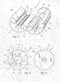
- a hand tool 1 is designed for removing a coating from a pipe or similar cylindrical object.
- the tool 1 is suitable for the removal of chromium coatings from metal pipes.
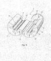
- the tool 1 comprises a grip 2 that is adapted for clamping fitment around a pipe and that defines an interior surface 3 in which is located at least one abrasive means whereby manual rotation of the pipe relative to the grip 2 causes the abrasive means to strip away an annular portion of the coating from the pipe.
- the size of the tool 1 is made appropriate for the diameter of the type of pipes with which it is to be used.
- the abrasive means comprises at least one file 4 that is embedded in the interior surface 3 of the grip 2, which is preferably made of a resilient material such as rubber or plastics that has been provided with a non-slip exterior surface 5, for example by being knurled or similar.
- the grip 2 could be made in separate pieces that can be squeezed together when located around a pipe, preferably the grip 2 comprises a pair of longitudinally extending jaws 6, 7 that are hinged together longitudinally, as at 8, so that when they are closed around a pipe by manual squeezing, the grip 2 is clamped around the pipe.
- the exterior of the grip 2 is preferably cylindrical in shape when the jaws 6, 7 are closed around a pipe and of a size suitable for being squeezed in one hand.
- the grip 2 could be made in larger sizes and the jaws 6, 7 could be squeezed together using pliers, a vice or other similar tools.
- abrasive means could be used, for example strips of abrasive paper or files 4, secured to the interior surface of the grip 2.
- the means comprises one or more abrasive surfaces 10 that extend linearly parallel to a longitudinal axis 9 of the grip.
- three evenly spaced files 4 are located in each jaw 6, 7 and are arranged such that their abrasive surfaces 10 lie on a cylindrical surface having a longitudinal axis coincident with the longitudinal axis 9 of the grip 2.
- This cylindrical surface is commensurate in diameter with the particular diameter of pipe for which the tool 1 has been designed, for example pipes for use in domestic plumbing.
- the files 4 are located in longitudinally extending slots 11 formed in the interior surface 3 of the grip 2 so that their abrasive surfaces 10 project from the surface 3.
- the slots 11 have a dove-tail profile that retains the files 4 within them but permit a relatively simple removal and replacement each file 4 when it has been worn down through use.
- the slots 11 need not have a dove-tail profile and the files 4 may be secured in the slots 11 by an adhesive or other securement means.
- a pipe locator may be located at one end of the grip 2 in order to facilitate consistency in use of the tool 1 by providing a stop against which an end of a length of pipe located in the tool 1 abuts.
- the locator facilitates the removal of such a length of coating without the user having to measure it as only a length at one end of a pipe commensurate with the length of the tool 1 can be inserted into the tool 1.
- the locator may also assist in the correct positioning of the pipe within the tool 1 and aligns it with the longitudinal axis 9.
- the locator comprises a circular plate 12 that has a diameter commensurate with the exterior diameter of the cylindrical grip 2 and that is integrally formed with or is secured to the end of one of the jaws 6, as shown in Fig. 1 .
- a disc or washer 13 is located on the inner side of the plate 12 and fits between the jaws 6, 7 when they are closed.
- the disc or washer 13 therefore has a diameter similar to the exterior diameter of the pipe.
- the disc or washer 13 may be secured to the plate 12 by adhesive, be integrally formed therewith or be secured thereto by a screw 14. In the latter case the disc or washer 13 is replaceable when it becomes worn.
- the disc or washer 13 may be replaced by a projection 15 that is adapted for insertion into one end of the pipe.
- the projection 15 is aligned with the axis 9 and projects into the interior of the grip 2 between the jaws 6, 7 so that it can be inserted into the end of the pipe that is located within the tool 1.
- the projection 15 is conical and tapers towards its tip 16 and has a diameter at its base which is commensurate with but slightly less than the interior diameter of the pipe so that the pipe is retained in position within the grip 2 when closed but does not prevent the grip 2 from being rotatable relative to the pipe.
- the projection 15 may be integrally formed with the plate 12 or be secured thereto by the screw 14.
- a pipe from which it is desired to remove an exterior coating is located within the jaws 6, 7 of the grip 2 so that the end of the pipe either abuts the disc or washer 13 or is fitted over the projection 15.
- the jaws 6, 7 are then closed and, while retained in this position manually, the tool 1 is rotated relative to the pipe.
- the files 4 then act to strip off an annular portion of the outer coating at the end of the pipe. It will be appreciated that because the abrasive surfaces 10 lie on a cylindrical surface that the stripped end of the pipe retains an exterior cylindrical profile once the outer coating has been stripped away. This ensures that the end of the pipe will still make a good water-tight connection with a push-fit connector or O-ring seal.
- the tool 1 is not limited for use in the removal of a coating from the end of a pipe. If the plate 12 is omitted from the tool 1, it can be used to remove an annular portion of a coating from any part of a length of pipe. The tool 1 could also be used in a similar way to remove a coating or annular portion of the outer surface of any cylindrical object of appropriate size.
Landscapes
- Engineering & Computer Science (AREA)
- Mechanical Engineering (AREA)
- Hand Tools For Fitting Together And Separating, Or Other Hand Tools (AREA)
- Polishing Bodies And Polishing Tools (AREA)
Applications Claiming Priority (2)
| Application Number | Priority Date | Filing Date | Title |
|---|---|---|---|
| GBGB1204077.0A GB201204077D0 (en) | 2012-03-08 | 2012-03-08 | A hand tool for removing pipe coatings |
| GB201303488A GB2500106B (en) | 2012-03-08 | 2013-02-27 | A hand tool for removing pipe coatings |
Publications (2)
| Publication Number | Publication Date |
|---|---|
| EP2636460A2 true EP2636460A2 (de) | 2013-09-11 |
| EP2636460A3 EP2636460A3 (de) | 2014-01-22 |
Family
ID=46003312
Family Applications (1)
| Application Number | Title | Priority Date | Filing Date |
|---|---|---|---|
| EP13250021.6A Withdrawn EP2636460A3 (de) | 2012-03-08 | 2013-03-01 | Handwerkzeug zur Entfernung von Rohrbeschichtungen |
Country Status (2)
| Country | Link |
|---|---|
| EP (1) | EP2636460A3 (de) |
| GB (2) | GB201204077D0 (de) |
Cited By (4)
| Publication number | Priority date | Publication date | Assignee | Title |
|---|---|---|---|---|
| US9975142B2 (en) | 2016-04-26 | 2018-05-22 | The Boeing Company | Fluid applicator tool and method of applying fluid to a tubular member |
| CN109605144A (zh) * | 2018-12-29 | 2019-04-12 | 王家钰 | 一种半自动管状零部件打磨装置 |
| CN110665909A (zh) * | 2019-10-10 | 2020-01-10 | 四川科特检测技术有限公司 | 一种管线外壁打磨方法 |
| CN114770330A (zh) * | 2022-05-24 | 2022-07-22 | 海安县石油科研仪器有限公司 | 一种石油钻杆表面除锈装置 |
Families Citing this family (1)
| Publication number | Priority date | Publication date | Assignee | Title |
|---|---|---|---|---|
| CN113183004B (zh) * | 2021-05-18 | 2022-09-23 | 广东峻佳建设有限公司 | 建筑工程预埋件外漏钢筋除锈装置及其使用方法 |
Family Cites Families (8)
| Publication number | Priority date | Publication date | Assignee | Title |
|---|---|---|---|---|
| US2922218A (en) * | 1957-03-27 | 1960-01-26 | Lewis Arthur | Pipe cleaning device |
| GB1335665A (en) * | 1971-04-19 | 1973-10-31 | Glynwed Steels Ltd | De-frazing apparatus |
| DE8414776U1 (de) * | 1984-05-15 | 1984-09-13 | Georg Fischer AG, Schaffhausen, CH, Niederlassung: Georg Fischer AG, 7700 Singen | Reinigungswerkzeug fuer rohre |
| US4998956A (en) * | 1990-06-27 | 1991-03-12 | Sherman Frederick R | Ski and snowboard sharpener |
| GB2395244A (en) * | 2002-11-15 | 2004-05-19 | Martin Thompson | Pipe cleaning device |
| US6855045B2 (en) * | 2003-01-22 | 2005-02-15 | Randy D. Laws | Tube surface cleaning device |
| US8069521B2 (en) * | 2007-08-09 | 2011-12-06 | Hubbell Incorporated | Hand-held electrical conductor cleaning apparatus |
| US20100122423A1 (en) * | 2008-11-20 | 2010-05-20 | James Lozar | Device for Simultaneously Cleaning and Deburring Pipe |
-
2012
- 2012-03-08 GB GBGB1204077.0A patent/GB201204077D0/en not_active Ceased
-
2013
- 2013-02-27 GB GB201303488A patent/GB2500106B/en active Active
- 2013-03-01 EP EP13250021.6A patent/EP2636460A3/de not_active Withdrawn
Non-Patent Citations (1)
| Title |
|---|
| None |
Cited By (5)
| Publication number | Priority date | Publication date | Assignee | Title |
|---|---|---|---|---|
| US9975142B2 (en) | 2016-04-26 | 2018-05-22 | The Boeing Company | Fluid applicator tool and method of applying fluid to a tubular member |
| CN109605144A (zh) * | 2018-12-29 | 2019-04-12 | 王家钰 | 一种半自动管状零部件打磨装置 |
| CN110665909A (zh) * | 2019-10-10 | 2020-01-10 | 四川科特检测技术有限公司 | 一种管线外壁打磨方法 |
| CN114770330A (zh) * | 2022-05-24 | 2022-07-22 | 海安县石油科研仪器有限公司 | 一种石油钻杆表面除锈装置 |
| CN114770330B (zh) * | 2022-05-24 | 2024-03-08 | 海安县石油科研仪器有限公司 | 一种石油钻杆表面除锈装置 |
Also Published As
| Publication number | Publication date |
|---|---|
| GB2500106B (en) | 2015-05-13 |
| GB201303488D0 (en) | 2013-04-10 |
| GB2500106A (en) | 2013-09-11 |
| EP2636460A3 (de) | 2014-01-22 |
| GB201204077D0 (en) | 2012-04-18 |
Similar Documents
| Publication | Publication Date | Title |
|---|---|---|
| EP2636460A2 (de) | Handwerkzeug zur Entfernung von Rohrbeschichtungen | |
| CN104540643B (zh) | 用于快速断开快速连接/断开连接器的手动工具 | |
| US7757590B2 (en) | Fastener holding device | |
| CN104084358A (zh) | 一种输油管道刷漆装置 | |
| US9744650B2 (en) | Drive assembly for use with the handle grip of a clamping device | |
| US20170348829A1 (en) | Drive assembly for use with the handle grip of a clamping device | |
| PL2190615T3 (pl) | Przyrząd do obróbki obwodowej rur z tworzywa sztucznego lu rur pokrytych tworzywem sztucznym | |
| CN204164268U (zh) | 钢索端点夹紧器 | |
| US3075219A (en) | Pipe cleaning tool | |
| US20080110303A1 (en) | Thread gripping tool | |
| CN109176334A (zh) | 一种适应多种场合的便于拆卸的钳子 | |
| CA2963963C (en) | Pinch clamp removal tool and method | |
| US20190136550A1 (en) | Drywall repair tool | |
| CN101450470A (zh) | 管子钳 | |
| US20170129082A1 (en) | Device For Removal of Broken Plug | |
| EP1793153A1 (de) | Rohrverbindung | |
| TWM519572U (zh) | 鎖固鉗 | |
| CN210025115U (zh) | 一种用于狭小空间拆装的防滑卡环钳 | |
| CN105977766B (zh) | 整形钳 | |
| US9707631B2 (en) | Plastic tube fitting removal tool | |
| CN105328608A (zh) | 一种活动扳手 | |
| US20090136306A1 (en) | Planing Apparatus And Method | |
| JP3016199U (ja) | 管切鋸取付体に設けた切断管端整形用具 | |
| US2276928A (en) | Cutting tool and holder | |
| CN205184691U (zh) | 多功能组合钳子 |
Legal Events
| Date | Code | Title | Description |
|---|---|---|---|
| PUAI | Public reference made under article 153(3) epc to a published international application that has entered the european phase |
Free format text: ORIGINAL CODE: 0009012 |
|
| AK | Designated contracting states |
Kind code of ref document: A2 Designated state(s): AL AT BE BG CH CY CZ DE DK EE ES FI FR GB GR HR HU IE IS IT LI LT LU LV MC MK MT NL NO PL PT RO RS SE SI SK SM TR |
|
| AX | Request for extension of the european patent |
Extension state: BA ME |
|
| PUAL | Search report despatched |
Free format text: ORIGINAL CODE: 0009013 |
|
| AK | Designated contracting states |
Kind code of ref document: A3 Designated state(s): AL AT BE BG CH CY CZ DE DK EE ES FI FR GB GR HR HU IE IS IT LI LT LU LV MC MK MT NL NO PL PT RO RS SE SI SK SM TR |
|
| AX | Request for extension of the european patent |
Extension state: BA ME |
|
| RIC1 | Information provided on ipc code assigned before grant |
Ipc: B08B 9/02 20060101AFI20131219BHEP Ipc: B24B 9/00 20060101ALI20131219BHEP Ipc: B23D 67/12 20060101ALI20131219BHEP |
|
| 17P | Request for examination filed |
Effective date: 20140714 |
|
| RBV | Designated contracting states (corrected) |
Designated state(s): AL AT BE BG CH CY CZ DE DK EE ES FI FR GB GR HR HU IE IS IT LI LT LU LV MC MK MT NL NO PL PT RO RS SE SI SK SM TR |
|
| 111L | Licence recorded |
Designated state(s): AL AT BE BG CH CY CZ DE DK EE ES FI FR GB GR HR HU IE IS IT LT LU LV MC MK MT NL NO PL PT RO RS SE SI SK SM TR Free format text: EXCLUSIVE LICENSE Name of requester: PLD PRODUCTS LIMITED, GB Effective date: 20140610 |
|
| 17Q | First examination report despatched |
Effective date: 20150402 |
|
| STAA | Information on the status of an ep patent application or granted ep patent |
Free format text: STATUS: THE APPLICATION IS DEEMED TO BE WITHDRAWN |
|
| 18D | Application deemed to be withdrawn |
Effective date: 20160616 |