EP2636632A1 - Commande de grue avec limite d'entraînement - Google Patents
Commande de grue avec limite d'entraînement Download PDFInfo
- Publication number
- EP2636632A1 EP2636632A1 EP12008290.4A EP12008290A EP2636632A1 EP 2636632 A1 EP2636632 A1 EP 2636632A1 EP 12008290 A EP12008290 A EP 12008290A EP 2636632 A1 EP2636632 A1 EP 2636632A1
- Authority
- EP
- European Patent Office
- Prior art keywords
- hoist
- control
- crane
- movement
- sea state
- Prior art date
- Legal status (The legal status is an assumption and is not a legal conclusion. Google has not performed a legal analysis and makes no representation as to the accuracy of the status listed.)
- Granted
Links
Images


Classifications
-
- B—PERFORMING OPERATIONS; TRANSPORTING
- B66—HOISTING; LIFTING; HAULING
- B66C—CRANES; LOAD-ENGAGING ELEMENTS OR DEVICES FOR CRANES, CAPSTANS, WINCHES, OR TACKLES
- B66C13/00—Other constructional features or details
- B66C13/04—Auxiliary devices for controlling movements of suspended loads, or preventing cable slack
-
- B—PERFORMING OPERATIONS; TRANSPORTING
- B66—HOISTING; LIFTING; HAULING
- B66C—CRANES; LOAD-ENGAGING ELEMENTS OR DEVICES FOR CRANES, CAPSTANS, WINCHES, OR TACKLES
- B66C13/00—Other constructional features or details
- B66C13/02—Devices for facilitating retrieval of floating objects, e.g. for recovering crafts from water
-
- B—PERFORMING OPERATIONS; TRANSPORTING
- B66—HOISTING; LIFTING; HAULING
- B66C—CRANES; LOAD-ENGAGING ELEMENTS OR DEVICES FOR CRANES, CAPSTANS, WINCHES, OR TACKLES
- B66C13/00—Other constructional features or details
- B66C13/04—Auxiliary devices for controlling movements of suspended loads, or preventing cable slack
- B66C13/08—Auxiliary devices for controlling movements of suspended loads, or preventing cable slack for depositing loads in desired attitudes or positions
- B66C13/085—Auxiliary devices for controlling movements of suspended loads, or preventing cable slack for depositing loads in desired attitudes or positions electrical
-
- B—PERFORMING OPERATIONS; TRANSPORTING
- B66—HOISTING; LIFTING; HAULING
- B66C—CRANES; LOAD-ENGAGING ELEMENTS OR DEVICES FOR CRANES, CAPSTANS, WINCHES, OR TACKLES
- B66C13/00—Other constructional features or details
- B66C13/18—Control systems or devices
-
- B—PERFORMING OPERATIONS; TRANSPORTING
- B66—HOISTING; LIFTING; HAULING
- B66C—CRANES; LOAD-ENGAGING ELEMENTS OR DEVICES FOR CRANES, CAPSTANS, WINCHES, OR TACKLES
- B66C23/00—Cranes comprising essentially a beam, boom, or triangular structure acting as a cantilever and mounted for translatory of swinging movements in vertical or horizontal planes or a combination of such movements, e.g. jib-cranes, derricks, tower cranes
- B66C23/18—Cranes comprising essentially a beam, boom, or triangular structure acting as a cantilever and mounted for translatory of swinging movements in vertical or horizontal planes or a combination of such movements, e.g. jib-cranes, derricks, tower cranes specially adapted for use in particular purposes
- B66C23/36—Cranes comprising essentially a beam, boom, or triangular structure acting as a cantilever and mounted for translatory of swinging movements in vertical or horizontal planes or a combination of such movements, e.g. jib-cranes, derricks, tower cranes specially adapted for use in particular purposes mounted on road or rail vehicles; Manually-movable jib-cranes for use in workshops; Floating cranes
- B66C23/52—Floating cranes
Definitions
- the present invention relates to a crane control for a crane having a hoist for lifting a load suspended on a rope.
- the crane control has an active sea state compensation, which compensates for the movement of the cable suspension point and / or a Lastabsetzthes due to the sea state at least partially by controlling the hoist.
- Such a crane control is from the DE 10 2008 024513 A1 known.
- a prediction device is provided, which predicts a future movement of the cable suspension point on the basis of the determined current seaward movement and a model of the seaward movement, wherein a path control of the load at least partially compensates for the predicted movement of the cable suspension point.
- the object of the present invention is to provide an improved crane control system.
- the present invention shows a crane control for a crane having a hoist for lifting a load suspended on a rope.
- the crane control has an active sea state compensation, which compensates for the movement of the cable suspension point and / or a Lastabsetzthes due to the sea state at least partially by a control of the hoist.
- the sea state compensation takes into account at least one limitation of the hoist in the calculation of the control of the hoist.
- the limitation of the hoist ensures that the hoist can actually follow the calculated due to the sea state compensation control commands and / or that the hoist or the crane is not damaged by the control.
- the swell compensation can take into account a maximum allowable jerk. This ensures that the hitch or the structure of the crane is not damaged by the control of the hoist due to the sea state compensation. In addition to a maximum permissible jerk, a steady course of the jerk can still be required.
- the swell compensation can take into account a maximum available power.
- the swell compensation can take into account a maximum available acceleration.
- a maximum available acceleration may be, for example, the maximum power of the drive of the hoist and / or the length of the already unwound rope and thereby acting on the hoist weight of the rope and / or due to the load of the hoist by the weight to be lifted result.
- the swell compensation can take into account a maximum available speed.
- the maximum available speed for the sea state compensation can also be as described above with regard to the maximum available acceleration.
- the crane control can have a calculation function which calculates the at least one limitation of the lifting mechanism.
- the calculation function can in particular evaluate sensor data and / or control signals for this purpose.
- the calculation function can be used to inform the sway compensation in each case of the currently valid restrictions of the hoist.
- the limitations of the hoist can change during a stroke, which according to the invention can be taken into account by the sea state compensation.
- the calculation function can calculate a currently available at least one kinematic limited size of the hoist, in particular the maximum available power and / or speed and / or acceleration of the hoist each current.
- the calculation function takes into account the length of the unwound cable and / or the cable force and / or the power available for driving the hoisting gear.
- the crane control can be used to control a hoist whose drive is connected to an energy store.
- the amount of energy stored in the energy store thereby influences the power available for driving the hoist.
- the amount of energy stored in the energy store or the power available for driving the hoist enters into the calculation function according to the present invention.
- the hoist according to the invention can be controlled hydraulically, wherein in the hydraulic circuit for driving the hoist winch of the hoist, a hydraulic energy storage is provided.
- an electric drive can be used. This can also be associated with an energy storage.
- the crane control further comprises a path planning module, which determines a trajectory based on the predicted movement of the cable suspension point and / or a Lastabsetzembls and taking into account the limitations of the hoist.
- the drive restrictions can be explicitly taken into account in the planning of the trajectories, in particular the drive limitation with regard to the power, the speed, the acceleration and / or the jerk.
- the trajectory can be a trajectory of the position and / or speed and / or acceleration of the hoisting gear.
- the path planning module has an optimization function which, on the basis of the predicted movement of the cable suspension point and / or a load release point and taking into account the limitation of the hoist, determines a trajectory which determines the residual movement of the load due to the movement of the cable suspension point and / or the differential movement between the load and the load settling point due to the movement of Lastabsetzembls minimized.
- the at least one drive restriction within the optimal control problem.
- the limitation of the drive with regard to power and / or speed and / or acceleration and / or jerk is considered within the optimal control problem.
- the optimization function advantageously calculates an optimum path based on a predicted vertical position and / or vertical speed of the cable suspension point and / or a load release point, which, taking into account the kinematic restrictions, minimizes the residual movement and / or differential movement of the load.
- the present invention includes a crane control for a crane having a hoist for lifting a load suspended on a rope.
- the crane control comprises an active sea state compensation, which compensates for the movement of the cable suspension point and / or a Lastabsetzsees due to the sea state at least partially by a control of the hoist.
- the sea state compensation in this case has a path planning module, which calculates a trajectory of the position and / or speed and / or acceleration of the lifting mechanism on the basis of a predicted movement of the cable suspension point and / or a load release point, which assumes a setpoint value for a downstream control of the lifting mechanism.
- This design of the sea state compensation results in a particularly stable and easy to implement control of the hoist. In particular, it is no longer necessary to reconstruct the unknown load position.
- control of the lifting mechanism can thereby return measured values to the position and / or speed of the hoisting winch.
- the path planning module thus provides as a setpoint position and / or speed of the hoist winch, which is adjusted in the downstream control with actual values.
- the control of the hoist takes into account the dynamics of the drive of the hoist winch by a pilot control.
- the precontrol can be based on an inversion of a physical model which describes the dynamics of the drive of the hoist winch.
- the hoist winch can be a hydraulically operated hoist winch.
- the first and second aspects of the present invention are each separately protected by the present application, and may be implemented separately and without the other aspect.
- the two aspects are combined according to the present invention.
- the path planning module according to the second aspect of the present invention takes into account at least one limitation of the hoist when determining the trajectory.
- the crane control according to the present invention may further comprise an operator control, which controls the hoist based on specifications of the operator.
- control for this purpose has two separate path planning modules, via which separate trajectories for the sea state compensation and for the operator control are calculated.
- these trajectories can be trajectories for the position and / or speed and / or acceleration of the hoisting gear.
- the trajectories given by the two separate path planning modules can be summed and used as setpoint values for the control and / or regulation of the hoisting gear.
- the division of at least one kinematic limited variable between sea state compensation and operator control is adjustable, the setting, for example, via a Weighting factor can be done, via which the maximum available power and / or speed and / or acceleration of the hoist between the sea state compensation and the operator control is divided.
- the operator control also takes into account at least one limitation of the drive, and in particular the maximum permissible jerk and / or a maximum available power and / or a maximum available acceleration and / or a maximum available speed.
- the optimization function of the swell compensation can determine a desired trajectory, which enters into the control and / or regulation of the hoist.
- the optimization function can calculate a setpoint trajectory of the position and / or speed and / or acceleration of the lifting mechanism, which enters into a setpoint for downstream control of the lifting mechanism.
- the optimization can be done via a discretization.
- the optimization can be carried out at each time step on the basis of an updated forecast of the movement of the load pick-up point.
- the first value of the desired trajectory can be used to control the lifting mechanism. If an updated desired trajectory is then available, again only its first value is used for regulation.
- the optimization function can operate at a lower sampling rate than the control. This makes it possible to choose larger sampling times for the compute-intensive optimization function, for the less computation-intensive control contrast, to achieve greater accuracy through lower sampling times.
- the optimization function relies on emergency trajectory planning if no valid solution can be found. This will ensure proper operation even if a valid solution can not be found.
- the crane control according to the present invention may comprise a measuring device which determines a current seaway movement from the sensor data.
- a measuring device which determines a current seaway movement from the sensor data.
- gyroscopes and / or inclination sensors can be used as sensors.
- the sensors can thereby be arranged on the crane or on a floating body on which the crane is arranged, for example on the crane base, and / or on a floating body on which the load setting position is arranged.
- the crane control may further include a forecasting device, which predicts a future movement of the cable suspension point and / or a Lastabsetziss based on the determined current sea state movement and a model of the sea state movement.
- the model of the swell movement used in the prediction device is independent of the properties, and in particular independent of the dynamics of the floating body.
- the crane control can be used independently of the floating body on which the crane and / or the load suspension position is arranged.
- the prediction device can thereby determine the prevailing modes of the seaway movement from the data of the measuring device. In particular, this can be done via a frequency analysis.
- the forecasting device can create a model of the seaway based on the particular prevailing modes. Based on this model, the future seaward movement can then be predicted.
- the forecasting device continuously parametrizes the model on the basis of the data of the measuring device.
- an observer can be used, which is parameterized continuously.
- the amplitude and the phase of the modes can be parameterized.
- the model is updated when the prevailing modes of the sea state change.
- the prediction device and the measuring device can be designed as described in the DE 10 2008 024513 A1 is described, the content of which is fully made the subject of the present application.
- the present invention further comprises a crane with a crane control as described above.
- the crane can be arranged on a float.
- the crane may be a ship crane. Alternatively, it may also be an offshore crane, a port crane or a crawler crane.
- the present invention further comprises a floating body with a crane according to the present invention, in particular a ship with a crane according to the invention.
- the present invention comprises the use of a crane according to the invention or a crane control according to the invention for raising and / or lowering a load located in the water and / or the use of a crane according to the invention or a crane control according to the invention for raising and / or lowering a load of and or on a load settling position in the water, for example on a ship.
- the present invention comprises the use of the crane according to the invention or the crane control according to the invention for deep-sea turns and / or the loading and / or unloading of ships.
- the present invention further includes a method of controlling a crane having a hoist for lifting a load suspended on a rope.
- a swell compensation by an automatic control of the hoist compensates for the movement of the cable suspension point and / or a Lastabsetzcons due to the sea state at least partially.
- the sea state compensation takes into account at least one limitation of the hoist in the calculation of the control of the hoist.
- the sea state compensation based on a predicted movement of the cable suspension point calculates a trajectory of the position and / or speed and / or acceleration of the hoist, which enters into a desired value for a downstream control of the hoist.
- the method according to the invention has the same advantages that have already been described with regard to crane control.
- the method can be carried out as described above.
- the two aspects according to the present invention can also be combined in the method.
- the method according to the invention can preferably be carried out by means of a crane control, as has been described above.
- the present invention further comprises software with code for carrying out the method according to the invention.
- the software can be stored on a machine-readable data carrier.
- a crane control according to the invention can be implemented.
- the crane control according to the invention is realized electronically, in particular by an electronic control computer.
- the control computer is advantageously connected to sensors.
- the control computer can be in communication with the measuring device.
- the control computer generates control signals for controlling the hoist.
- the hoist may preferably be a hydraulically driven hoist.
- the control calculation of the crane control according to the invention can according to the invention control the pivoting angle of at least one hydraulic displacement machine of the hydraulic drive system and / or at least one valve of the hydraulic drive system.
- a hydraulic accumulator is provided in the hydraulic drive system, via which energy can be stored when lowering the load, which is then available as additional power when lifting the load.
- control of the hydraulic accumulator takes place separately for the control of the hoist according to the invention.
- an electric drive can be used.
- This can also include an energy store.
- Figure 0 shows an embodiment of a crane 1 with a crane control according to the invention for controlling the hoist 5.
- the hoist 5 has a hoist winch, which moves the cable 4.
- the cable 4 is guided over a cable suspension point 2, in the exemplary embodiment a deflection roller at the end of the crane boom, on the crane. By moving the cable 4, a load hanging on the rope 3 can be raised or lowered.
- At least one sensor may be provided which measures the position and / or speed of the hoist and transmits corresponding signals to the crane control.
- At least one sensor can be provided which measures the cable force and transmits corresponding signals to the crane control.
- the sensor can be arranged in the region of the crane structure, in particular in a fastening of the winch 5 and / or in a fastening of the pulley 2.
- the crane 1 is arranged in the embodiment on a float 6, here a ship. Like also in Figure 0 to recognize the float 6 moves due to the sea at its six degrees of freedom. As a result, the arranged on the float 6 crane 1 and the cable suspension point 2 is moved.
- the crane control according to the present invention may have an active sea state compensation, which at least partially compensates for a control of the hoist and the movement of the cable suspension point 2 due to the sea.
- the vertical movement of the cable suspension point due to the sea is at least partially compensated.
- the sea state compensation may include a measuring device which determines a current sea state movement from sensor data.
- the measuring device may comprise sensors which are arranged on the crane foundation.
- these may be gyroscopes and / or inclination angle sensors.
- three gyroscopes and three inclination angle sensors are provided.
- a prediction device can be provided which predicts a future movement of the cable suspension point 2 on the basis of the determined seaward movement and a model of the seaward movement.
- the forecasting device alone predicts the vertical movement of the cable suspension point.
- Sometimes. can be converted in the context of the measuring and / or the forecasting device, a movement of the ship at the point of the sensors of the measuring device in a movement of the cable suspension point.
- the forecasting device and the measuring device are advantageously designed as shown in the DE 10 2008 024513 A1 is described in more detail.
- the crane according to the invention could also be a crane, which is used for lifting and / or lowering a load from or onto a crane placed on a float Lastabsetzrios is used, which therefore moves with the sea state.
- the forecasting device must in this case predict the future movement of the load take-off point. This can be done analogously to the procedure described above, wherein the sensors of the measuring device are arranged on the float of Lastabsetzthes.
- the crane may be, for example, a harbor crane, an offshore crane or a crawler crane.
- the hoist winch of the hoist 5 is hydraulically driven in the embodiment.
- a hydraulic circuit of hydraulic pump and hydraulic motor is provided, via which the hoist winch is driven.
- a hydraulic accumulator can be provided, via which energy is stored when the load is lowered, so that this energy is available when lifting the load.
- an electric drive could be used. This could also be connected to an energy storage.
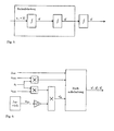
- a follow-up control consisting of a precontrol and a feedback in the form of a two-degree-of-freedom structure is used in the exemplary embodiment.
- the feedforward control is calculated by a differential parameterization and requires twice continuously differentiable reference trajectories. Decisive in the planning is that the drive can follow the given trajectories. Thus, limitations of the hoist must be considered.
- the starting point for consideration is the vertical position and / or speed of the cable suspension point Z ⁇ a H and Z ⁇ ⁇ a H . which eg with the help of in the DE 10 2008 024 513 algorithm can be predicted over a fixed time horizon.
- the hand lever signal of the crane driver via which he moves the load in the inertial coordinate system, is also included.
- v max and a max are divided by means of a weighting factor 0 ⁇ k l ⁇ 1 1 (cf. Fig. 1 ). This is specified by the crane driver and thus allows the individual distribution of power, which is available for the compensation or the method of the load.
- a weighting factor 0 ⁇ k l ⁇ 1 1 (cf. Fig. 1 ).
- a change of k l can be carried out during operation. Since the maximum possible travel speed or acceleration depends on the total mass of rope and load, v max and a max can also change during operation. Therefore, the valid values are also transferred to the trajectory planning.
- the crane operator can easily and intuitively adjust the influence of the active sea state compensation.
- the first part of the chapter first explains the generation of reference trajectories y a * . y ⁇ a * and y ⁇ a * for compensating the vertical movement of the cable suspension point.
- the essential aspect here is that with the planned trajectories the vertical movement is compensated as far as is possible on the basis of the given restrictions set by k l .
- the second part of the chapter deals with the planning of trajectories y l * . y ⁇ l * and y ⁇ l * for moving the load. These are generated directly from the hand lever signal of the crane driver W hh . The calculation is done by adding the maximum allowable jerk.
- trajectory planning for the compensating movement of the hoisting winch, sufficiently smooth trajectories are to be generated from the predicted vertical positions and speeds of the rope suspending point, taking into account the valid drive restrictions.
- This task is considered below as a limited optimization problem, which is to be solved online in each time step. Therefore, the approach is similar to the design of a model-predictive control, but in the sense of a model-predictive trajectory generation.
- an optimal time sequence for the compensation movement can then be determined.
- an emergency function can be implemented in this concept, in case the optimization does not find a valid solution, independently of the regulation. It consists of a simplified trajectory planning, whereupon the regulation resorts to such an emergency situation and continues to control the winds.
- the third derivation must be made at the earliest y ... a * be considered as capable of jumping.
- making only the fourth derivative y a * 4 can be considered as capable of jumping.
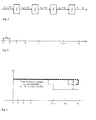
- the jerk y ... a * plan at least steadily and the Trajektoriengener mich for the compensation movement is based on the in Fig. 2 illustrated fourth order integrator chain.
- this time-continuous model first becomes on the grid ⁇ 0 ⁇ ⁇ 1 ⁇ ... ⁇ ⁇ K p - 1 ⁇ ⁇ K p where K p represents the number of prediction steps for the prediction of the vertical movement of the cable suspension point.
- Fig. 3 makes it clear that the selected grid is not equidistant, which reduces the number of necessary nodes on the horizon. This makes it possible to keep the dimension of the optimal control problem to be solved small.
- the influence of the grosser discretization towards the end of the horizon does not adversely affect the planned trajectory since the prediction of vertical position and velocity towards the end of the prediction horizon is less accurate.
- a trajectory is to be planned which follows the predicted vertical movement of the cable suspension point as close as possible and at the same time satisfies the given restrictions.
- r u evaluates the actuating effort. While r u , q w, 3 and q w, 4 are constant over the entire prediction horizon, q w , 1 and q w , 2 are chosen as a function of the time step ⁇ k . As a result, reference values at the beginning of the prediction horizon can be weighted more heavily than those at the end. Thus, one can map the decreasing accuracy of the vertical motion forecast in the quality function with increasing forecast time.
- the weights q w, 3 and q w , 4 only penalize deviations from zero, which is why they are smaller than the weights for the position q w. 1 ( ⁇ k ) and speed q w , 2 ( ⁇ k ) are selected.
- the jerk limitations are j max and the derivative of the jerk d dt ⁇ j Max constant. To the life of the hoist winch and the whole Cranes are chosen for maximum shock load. There are no restrictions on the position condition.
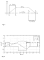
- Fig. 4 clarifies this procedure based on the speed limit.
- care must also be taken that it matches its maximum permissible derivative. This means that, for example, the speed limit ( 1 -k l ) v max may be reduced at most as fast as the current acceleration limitation (1 k l ) a max permits.
- a constrained initial condition x a ( ⁇ 0 ) always has a solution which in turn does not violate the updated constraints. However, it takes the complete prediction horizon until a changed restriction finally affects the planned trajectories at the beginning of the horizon.
- the optimal control problem is through to be minimized square merit function (1.5), the system model (1.4) and the inequality constraints of (1.8) and (1.9) in the form of a linear-quadratic optimization problem (QP problem for Q uadratic P rogramming PROBLEM) completely given.
- QP problem for Q uadratic P rogramming PROBLEM
- the value x a ( ⁇ 1 ) calculated in the last optimization step for the time step ⁇ 1 is used as the initial condition.
- the actual solution to the QP problem is calculated in each time step using a numerical method known as the QP solver.
- the sampling time for the trajectory planning of the compensatory motion is greater than the discretization time of all remaining components of the active sea state compensation; thus ⁇ ⁇ > ⁇ t true.
- the simulation of the integrator chain takes place Fig. 2 outside the optimization with the faster sampling time ⁇ t instead.
- the states x a ( ⁇ 0 ) are used as an initial condition for the simulation, and the manipulated variable at the beginning of the prediction horizon u a ( ⁇ 0 ) is written to the integrator chain as a constant input.
- Fig. 5 shows, it also serves as the input of a third-order integrator chain.
- the planned trajectories must also meet the currently valid speed and acceleration restrictions which result for the lever control in k l v max and k l a max .
- the hand lever signal of the crane driver -100 ⁇ w hh ⁇ 100 is interpreted as relative speed specification with respect to the currently maximum permissible speed k l v max .
- the setpoint speed currently given by the hand lever depends on the hand lever position W hh , the variable weighting factor k l and the current maximum permissible winch speed V max .
- the task of trajectory planning for the hand lever control can now be specified as follows: From the setpoint speed given by the hand lever, a continuously differentiable speed profile is to be generated so that the acceleration has a steady course. As a method for this task offers a so-called jerk-on.
- the maximum permissible jerk j max in a first phase acts on the input of the integrator chain until the maximum permissible acceleration is reached.
- the speed is increased with constant acceleration; and in the last phase, the maximum permissible negative jerk is switched on so that the desired final speed is reached.
- Fig. 7 illustrates an exemplary course of the jerk for a speed change together with the switching times.
- T / 0 denotes the time at which rescheduling takes place.
- the times T l , 1 , T l , 2 and T l , 3 each refer to the calculated switching times between the individual phases. Their calculation is outlined in the following paragraph.
- a new situation occurs as soon as the target speed v hh * or the currently valid maximum acceleration for the hand lever control k l a max changes.
- the desired speed may change due to a new hand lever position W hh or by a new specification of k l or V max (cf. Fig. 6 ). Analogously, a variation of the maximum valid acceleration by k l or a max is possible.
- y ⁇ l * T l . 1 y ⁇ l * T l . 0 + ⁇ ⁇ T 1 ⁇ y ⁇ l * T l . 0 + 1 2 ⁇ ⁇ ⁇ T 1 2 ⁇ u l . 1 .
- y ⁇ l * T l . 1 y ⁇ l * T l . 0 + ⁇ ⁇ T 1 ⁇ u j . 1
- y ⁇ l * T l . 2 y ⁇ l * T l . 1 + ⁇ ⁇ T 2 ⁇ y ⁇ l * T l . 1 .
- y ⁇ l * T l . 2 y ⁇ l * T l . 1 .
- u l , 2 0 was assumed.
- y ⁇ l * T l . 3 y ⁇ l * T l . 2 + ⁇ ⁇ T 3 ⁇ y ⁇ l * T l . 2 + 1 2 ⁇ ⁇ ⁇ T 3 2 ⁇ u l . 3 .
- y ⁇ l * T l . 3 y ⁇ l * T l . 2 + ⁇ ⁇ T 3 ⁇ u l . 3 ,
- the speed and acceleration curves to be planned y ⁇ l * and y ⁇ l * can be calculated analytically with the individual switching times. It should be noted that the planned by the switching times trajectories are often not completely traversed because before reaching the switching time T l, 3 enters a new situation, thereby rescheduling takes place and new switching times be calculated. As already mentioned, a new situation occurs due to a change in W hh , V max , a max or k l .
- Fig. 8 shows a trajectory exemplified by the method presented.
- the course of the trajectories includes both cases, which can occur on the basis of (1.24).
- the maximum allowable acceleration due to the hand lever position is not fully achieved.
- the associated position history is calculated according to Fig. 5 by integrating the velocity profile, the position being initialized at startup by the rope length currently being handled by the hoist winch.
- the control consists of two different modes of operation: the active sea state compensation for decoupling the vertical load movement from the ship movement with free-hanging load and the constant voltage control to avoid slack rope, as soon as the load is deposited on the seabed.
- the sea state compensation is initially active. Based on a detection of the settling process is automatically switched to the constant voltage control.
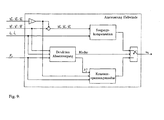
- Fig. 9 illustrates the overall concept with the associated control and control variables.
- each of the two different modes of operation could also be implemented without the other mode of operation.
- a constant voltage mode as described below, can also be used independently of the use of the crane on a ship and independently of an active sea state compensation.
- Active hoist compensation is intended to control the hoist winch so that the winch movement controls the vertical movement of the rope suspension point z a H compensates and the crane operator moves the load with the help of the hand lever in the considered as inertial h-coordinate system.
- the driver In order for the driver to have the required predictive behavior for minimizing the compensation error, it is converted by a pilot control and stabilization part in the form of a two-degree-of-freedom structure.
- the feedforward control is calculated from a differential parameterization with the aid of the flat output of the wind dynamics and results from the planned trajectories for moving the load y l * . y ⁇ l * and y ⁇ l * and the negative trajectories for the compensation movement - y a * .
- the resulting desired trajectories for the system output of the drive dynamics or the wind dynamics are with y H * . y ⁇ H * and y ⁇ H * designated. They represent the target position, speed and acceleration for the winch movement and thus for the winding and unwinding of the rope.
- the cable force at the load F sl should be regulated to a constant amount in order to avoid slack rope. Therefore, in this mode of operation, the hand lever is deactivated and the trajectories planned from the hand lever signal are no longer applied.
- the control of the winch is again by a two-degree-of-freedom structure with pilot control and stabilization part.
- the length / s is obtained indirectly from the angle of wind ⁇ h measured using an incremental encoder and the winding radius r h (j l ) dependent on the winding position j l .
- the associated cable speed i s can be calculated by numerical differentiation with suitable low-pass filtering.
- the cable force F c acting on the cable suspension point is detected by means of a force measuring axis.
- Fig. 10 illustrates the control of the hoist winch for the active sea state compensation with a block diagram in the frequency domain.
- the compensation of the vertical movement of the cable suspension point acting as an input disturbance on the cable system G s, z ( s ) takes place Z a H s purely pre-taxing; Rope and load dynamics are neglected.
- the rope's own dynamics are excited, but in practice it can be assumed that the resulting load movement in the water is strongly damped and decays very rapidly.
- Neglecting the compensation movement Y a * s can be the reference size Y H * s be approximated at constant or stationary Handhebelauslenkung as a ramp-shaped signal, since in such a case, a constant target speed v hh * is present.
- the open chain K a (s) G h (s) must therefore have l 2 behavior [9].
- the decrease in the negative spring force ⁇ F c is calculated in each case with respect to the last high point F c in the measured force signal F c .
- the force signal is preprocessed by a corresponding low-pass filter.
- X 1 ⁇ 1 and the maximum value ⁇ F c , max were determined experimentally.
- the two parameters ⁇ 2 ⁇ 1 and F c, max were also determined experimentally.
- the crane operator manually maneuvers the change from the constant tension mode to the active sea state compensation with the load suspended.
- Fig. 11 shows the converted control of the hoist winch in the constant voltage mode in a block diagram in the frequency domain.
- the output of the cable system F c (s) ie the force measured at the cable suspension point, is returned instead of the output of the winch system Y h (s) .
- the measured force F c (s) is composed according to (2.12) from the force change ⁇ F c (s) and the static gravitational force m e g + ⁇ s l s g , which is denoted M (s) in the image area.
- the cable system is again approximated as a spring-mass system.
- the precontrol F (s) of the two-degree-of-freedom structure is identical to that for active sea state compensation and given by (2.2) or (2.3). However, in the constant voltage mode, the hand lever signal is not applied, which is why the reference trajectory only from the negative target speed and - acceleration - y ⁇ a * and - y ⁇ a * exists for the compensation movement.
- the pilot control component initially compensates for the vertical movement of the cable suspension point Z a H s , However, there is no direct stabilization of the winch position by a return of Y h (s). This is done indirectly by the return of the measured force signal.
- the compensation error E a (s) is compensated by a stable transfer function G CT, 1 (S) and the wind position stabilized indirectly.
- the request to the controller K s (s) also results in this case from the expected command signal F c * s . which after a transition phase by the constant desired force F c * from (2.21).
- the open chain must have K s (s) G h (s) G s , F (s) / behaviors.
Landscapes
- Engineering & Computer Science (AREA)
- Mechanical Engineering (AREA)
- Automation & Control Theory (AREA)
- Control And Safety Of Cranes (AREA)
- Jib Cranes (AREA)
Applications Claiming Priority (1)
| Application Number | Priority Date | Filing Date | Title |
|---|---|---|---|
| DE102012004803A DE102012004803A1 (de) | 2012-03-09 | 2012-03-09 | Kransteuerung mit Antriebsbeschränkung |
Publications (2)
| Publication Number | Publication Date |
|---|---|
| EP2636632A1 true EP2636632A1 (fr) | 2013-09-11 |
| EP2636632B1 EP2636632B1 (fr) | 2019-02-13 |
Family
ID=47522219
Family Applications (1)
| Application Number | Title | Priority Date | Filing Date |
|---|---|---|---|
| EP12008290.4A Active EP2636632B1 (fr) | 2012-03-09 | 2012-12-12 | Commande de grue avec limite d'entraînement |
Country Status (6)
| Country | Link |
|---|---|
| US (1) | US9266700B2 (fr) |
| EP (1) | EP2636632B1 (fr) |
| JP (1) | JP6243128B2 (fr) |
| KR (1) | KR20130103365A (fr) |
| CN (1) | CN103303797B (fr) |
| DE (1) | DE102012004803A1 (fr) |
Cited By (2)
| Publication number | Priority date | Publication date | Assignee | Title |
|---|---|---|---|---|
| WO2016193713A1 (fr) * | 2015-06-02 | 2016-12-08 | Marine Electrical Consulting Limited | Procédé et appareil de compensation adaptative de mouvement |
| CN116101445A (zh) * | 2023-01-12 | 2023-05-12 | 江苏恒赛海洋科技有限公司 | 一种绳牵引式波浪补偿平台 |
Families Citing this family (25)
| Publication number | Priority date | Publication date | Assignee | Title |
|---|---|---|---|---|
| DE102012004802A1 (de) * | 2012-03-09 | 2013-09-12 | Liebherr-Werk Nenzing Gmbh | Kransteuerung mit Aufteilung einer kinematisch beschränkten Größe des Hubwerks |
| JP5829968B2 (ja) * | 2012-04-06 | 2015-12-09 | トヨタ自動車株式会社 | 多関節ロボット、その関節協調制御装置および方法 |
| CN105439016A (zh) * | 2014-10-11 | 2016-03-30 | 徐州重型机械有限公司 | 起重机工作幅度补偿方法和装置 |
| US9849944B2 (en) * | 2015-10-05 | 2017-12-26 | Keppel Offshore & Marine Technology Centre Pte. Ltd. | System and method for guiding cargo transfer between two bodies |
| CN105523476B (zh) * | 2015-12-31 | 2017-09-15 | 北京起重运输机械设计研究院 | 一种桥式起重机防摇控制方法和系统 |
| EP3226095A1 (fr) | 2016-03-31 | 2017-10-04 | Fraunhofer-Gesellschaft zur Förderung der angewandten Forschung e.V. | Système et procédé de navigation d'un véhicule de plongée à navigation autonome lors de l'entrée dans une station d'arrêt |
| DE102017125715A1 (de) * | 2016-11-09 | 2018-05-09 | Liebherr-Werk Biberach Gmbh | Vorrichtung zur Kompensation von Schrägzug bei Kranen |
| WO2018160681A1 (fr) * | 2017-02-28 | 2018-09-07 | J. Ray Mcdermott, S.A. | Levage navire-navire en mer avec assistance de suivi de cible |
| US11066279B2 (en) * | 2017-04-24 | 2021-07-20 | Itrec B.V. | Motion compensating crane for use on an offshore vessel |
| EP3601793B1 (fr) * | 2017-06-12 | 2024-05-29 | Siemens Gamesa Renewable Energy A/S | Agencement d'installation d'éolienne offshore |
| EP3461783B1 (fr) * | 2017-09-29 | 2019-11-13 | B&R Industrial Automation GmbH | Équipement de levage et procédé de commande d'un équipement de levage |
| JP7151223B2 (ja) | 2018-07-09 | 2022-10-12 | 株式会社タダノ | クレーンおよびクレーンの制御方法 |
| JP7172243B2 (ja) * | 2018-07-25 | 2022-11-16 | 株式会社タダノ | クレーンおよびクレーンの制御システム |
| JP7172256B2 (ja) * | 2018-07-31 | 2022-11-16 | 株式会社タダノ | クレーン |
| EP3653562B1 (fr) * | 2018-11-19 | 2026-04-15 | ABB Schweiz AG | Procédé et régulateur d'oscillation permettant de réguler les oscillations d'un système technique oscillant |
| WO2020163288A2 (fr) | 2019-02-05 | 2020-08-13 | J. Ray Mcdermott, S.A. | Système et procédés pour déterminer une position relative et un mouvement relatif d'objets |
| EP4043967A4 (fr) * | 2019-10-11 | 2023-11-01 | Tadano Ltd. | Système de commande et grue |
| CN112456361A (zh) * | 2020-11-25 | 2021-03-09 | 西北工业大学 | 一种减小吊放声纳液压绞车水下分机摆动幅度的控制方法 |
| CN116547227A (zh) * | 2020-11-30 | 2023-08-04 | 杰富意钢铁株式会社 | 货物装卸运送路径生成方法、货物装卸运送起重机及货物装卸运送方法 |
| CN113928991B (zh) * | 2021-09-09 | 2023-09-01 | 山东建筑大学 | 一种塔机起重臂臂端轨迹的监测方法及装置 |
| EP4159662B1 (fr) * | 2021-09-30 | 2025-06-11 | Abb Schweiz Ag | Procédé de fonctionnement d'une grue, système et élément de programme informatique |
| CN114148917B (zh) * | 2021-12-03 | 2025-08-08 | 中铝智能科技发展有限公司 | 一种基于0-1规划的桥式起重机调速控制方法 |
| CN115924740B (zh) * | 2022-12-29 | 2023-11-03 | 中铁建工集团有限公司 | 一种大跨度钢结构不同步提升控制方法 |
| US20240286280A1 (en) * | 2023-02-24 | 2024-08-29 | Sanctuary Cognitive Systems Corporation | Method and system of generating a feasible smooth reference trajectory for an actuator |
| CN116692616B (zh) * | 2023-07-26 | 2025-05-20 | 南通市准航电缆有限公司 | 一种电缆卷取控制方法 |
Citations (4)
| Publication number | Priority date | Publication date | Assignee | Title |
|---|---|---|---|---|
| US6505574B1 (en) * | 2001-09-05 | 2003-01-14 | The United States Of America As Represented By The Secretary Of The Navy | Vertical motion compensation for a crane's load |
| WO2005090226A1 (fr) * | 2004-03-19 | 2005-09-29 | Subsea 7 Bv | Dispositif et procede de compensation du pilonnement |
| EP1757554A2 (fr) * | 2005-08-24 | 2007-02-28 | Rockwell Automation Technologies, Inc. | Dispositif anti-ballant pour une grue |
| DE102008024513A1 (de) | 2008-05-21 | 2009-11-26 | Liebherr-Werk Nenzing Gmbh, Nenzing | Kransteuerung mit aktiver Seegangsfolge |
Family Cites Families (13)
| Publication number | Priority date | Publication date | Assignee | Title |
|---|---|---|---|---|
| GB2132972B (en) * | 1983-01-05 | 1986-01-15 | Ruston Bucyrus Ltd | Crane hoist protection system |
| DE3418026C2 (de) * | 1984-05-15 | 1987-04-02 | Mannesmann Rexroth GmbH, 8770 Lohr | Winde zum Aufnehmen von schwimmenden Lasten bei Seegang |
| US4624450A (en) | 1984-09-20 | 1986-11-25 | Paccar Inc. | Constant tension hoisting system |
| DE3643114C2 (de) | 1986-01-13 | 1995-06-01 | Rexroth Mannesmann Gmbh | Windensteuerung mit Seegangsfolgeeinrichtung |
| DE19645812C1 (de) | 1996-11-07 | 1998-02-26 | Stahl R Foerdertech Gmbh | Steuerungsanordnung mit Erkennung des Gewichts der Last |
| US6216789B1 (en) * | 1999-07-19 | 2001-04-17 | Schlumberger Technology Corporation | Heave compensated wireline logging winch system and method of use |
| WO2002027684A1 (fr) | 2000-09-27 | 2002-04-04 | Oceaneering International, Inc. | Procede et systeme pour controler un deploiement rapide |
| ES2260313T3 (es) * | 2000-10-19 | 2006-11-01 | Liebherr-Werk Nenzing Gmbh | Grua o excavadora para el volteado de una carga suspendida de un cable portacarga con amortiguacion de la oscilacion de la carga. |
| US7793763B2 (en) * | 2003-11-14 | 2010-09-14 | University Of Maryland, Baltimore County | System and method for damping vibrations in elevator cables |
| NO336258B1 (no) * | 2007-09-19 | 2015-07-06 | Nat Oilwell Varco Norway As | Fremgangsmåte og anordning for løftkompensering. |
| DE102009032269A1 (de) | 2009-07-08 | 2011-01-13 | Liebherr-Werk Nenzing Gmbh | Kransteuerung zur Ansteuerung eines Hubwerkes eines Kranes |
| DE102009041662A1 (de) * | 2009-09-16 | 2011-03-24 | Liebherr-Werk Nenzing Gmbh, Nenzing | System zum Erfassen der Lastmasse einer an einem Hubseil eines Kranes hängenden Last |
| CN202054550U (zh) * | 2011-04-28 | 2011-11-30 | 中船华南船舶机械有限公司 | 恒张力波浪补偿装置 |
-
2012
- 2012-03-09 DE DE102012004803A patent/DE102012004803A1/de not_active Withdrawn
- 2012-12-12 EP EP12008290.4A patent/EP2636632B1/fr active Active
-
2013
- 2013-02-27 KR KR1020130021062A patent/KR20130103365A/ko not_active Ceased
- 2013-03-07 US US13/788,856 patent/US9266700B2/en active Active
- 2013-03-08 JP JP2013046505A patent/JP6243128B2/ja active Active
- 2013-03-11 CN CN201310076824.2A patent/CN103303797B/zh not_active Expired - Fee Related
Patent Citations (4)
| Publication number | Priority date | Publication date | Assignee | Title |
|---|---|---|---|---|
| US6505574B1 (en) * | 2001-09-05 | 2003-01-14 | The United States Of America As Represented By The Secretary Of The Navy | Vertical motion compensation for a crane's load |
| WO2005090226A1 (fr) * | 2004-03-19 | 2005-09-29 | Subsea 7 Bv | Dispositif et procede de compensation du pilonnement |
| EP1757554A2 (fr) * | 2005-08-24 | 2007-02-28 | Rockwell Automation Technologies, Inc. | Dispositif anti-ballant pour une grue |
| DE102008024513A1 (de) | 2008-05-21 | 2009-11-26 | Liebherr-Werk Nenzing Gmbh, Nenzing | Kransteuerung mit aktiver Seegangsfolge |
Cited By (2)
| Publication number | Priority date | Publication date | Assignee | Title |
|---|---|---|---|---|
| WO2016193713A1 (fr) * | 2015-06-02 | 2016-12-08 | Marine Electrical Consulting Limited | Procédé et appareil de compensation adaptative de mouvement |
| CN116101445A (zh) * | 2023-01-12 | 2023-05-12 | 江苏恒赛海洋科技有限公司 | 一种绳牵引式波浪补偿平台 |
Also Published As
| Publication number | Publication date |
|---|---|
| JP6243128B2 (ja) | 2017-12-06 |
| KR20130103365A (ko) | 2013-09-23 |
| US20130245817A1 (en) | 2013-09-19 |
| EP2636632B1 (fr) | 2019-02-13 |
| JP2013184826A (ja) | 2013-09-19 |
| CN103303797B (zh) | 2016-12-28 |
| DE102012004803A1 (de) | 2013-09-12 |
| CN103303797A (zh) | 2013-09-18 |
| US9266700B2 (en) | 2016-02-23 |
Similar Documents
| Publication | Publication Date | Title |
|---|---|---|
| EP2636632B1 (fr) | Commande de grue avec limite d'entraînement | |
| EP2636635B1 (fr) | Commande de grue avec mode de traction de câble | |
| EP2636636B1 (fr) | Commande de grue avec répartition de la grandeur du dispositif de levage réduite par cinématique | |
| EP3649072B1 (fr) | Grue et procédé de commande d'une telle grue | |
| EP4013713B1 (fr) | Grue et procédé de commande d'une telle grue | |
| DE102018005068A1 (de) | Kran und Verfahren zum Steuern eines solchen Krans | |
| EP2272786B1 (fr) | Commande de grue pour la commande d'un dispositif de levage de grue | |
| EP1628902B1 (fr) | Grue ou excavatrice destinee a la manipulation d'une charge suspendue a un cable presentant un systeme de guidage optimise | |
| EP2272784B1 (fr) | Grue pour envelopper une charge suspendue à un câble porteur | |
| EP2298687B1 (fr) | Système de détection de la masse de charge d'une charge suspendue à une corde de levage de grue | |
| EP2123588B1 (fr) | Commande de grue dotée d'un suivi actif de houle | |
| DE19907989B4 (de) | Verfahren zur Bahnregelung von Kranen und Vorrichtung zum bahngenauen Verfahren einer Last | |
| AT520008B1 (de) | Verfahren zum Dämpfen von Drehschwingungen eines Lastaufnahmeelements einer Hebeeinrichtung | |
| DE102009030784A1 (de) | Verfahren zum Steuern des Betriebs eines Fahrzeugs | |
| DE102015100669A1 (de) | Anti-pendel-steuerverfahren mit einstellbarer unterstützung für den transport einer schwebenden last | |
| EP2987759B1 (fr) | Grue ayant un mouvement oscillant défini pour atteindre un emplacement cible | |
| WO2023025643A1 (fr) | Grue à tour pivotante, procédé et unité de commande pour faire fonctionner une grue à tour pivotante, chariot roulant et mécanisme de roulement pour chariot | |
| EP4339379A1 (fr) | Outil de travail doté d'une pince mécanique pour parois moulées et procédé de réalisation d'une étape de travail d'un tel outil | |
| EP4406905A1 (fr) | Procédé et dispositif de fonctionnement d'une grue à flèche rotative et grue à flèche rotative | |
| DE102005002192B4 (de) | Verfahren zum Betrieb einer Krananlage, insbesondere eines Containerkrans, sowie Krananlage, insbesondere Containerkran | |
| DE202023002939U1 (de) | Vorrichtung zum Betreiben eines Auslegerdrehkrans sowie Auslegerdrehkran | |
| EP4174013A1 (fr) | Procédé de déplacement d'une charge à l'aide d'une grue | |
| EP2110357A1 (fr) | Procédé d'amortissement d'oscillations d'une charge de biens en vrac guidée par une grue, programme de commande et système d'automatisation de grue |
Legal Events
| Date | Code | Title | Description |
|---|---|---|---|
| PUAI | Public reference made under article 153(3) epc to a published international application that has entered the european phase |
Free format text: ORIGINAL CODE: 0009012 |
|
| AK | Designated contracting states |
Kind code of ref document: A1 Designated state(s): AL AT BE BG CH CY CZ DE DK EE ES FI FR GB GR HR HU IE IS IT LI LT LU LV MC MK MT NL NO PL PT RO RS SE SI SK SM TR |
|
| AX | Request for extension of the european patent |
Extension state: BA ME |
|
| 17P | Request for examination filed |
Effective date: 20140311 |
|
| STAA | Information on the status of an ep patent application or granted ep patent |
Free format text: STATUS: EXAMINATION IS IN PROGRESS |
|
| 17Q | First examination report despatched |
Effective date: 20170201 |
|
| RIC1 | Information provided on ipc code assigned before grant |
Ipc: B66C 13/06 20060101AFI20180730BHEP Ipc: B66C 13/02 20060101ALI20180730BHEP Ipc: B66D 1/52 20060101ALI20180730BHEP Ipc: B66C 13/08 20060101ALI20180730BHEP |
|
| GRAP | Despatch of communication of intention to grant a patent |
Free format text: ORIGINAL CODE: EPIDOSNIGR1 |
|
| STAA | Information on the status of an ep patent application or granted ep patent |
Free format text: STATUS: GRANT OF PATENT IS INTENDED |
|
| INTG | Intention to grant announced |
Effective date: 20180920 |
|
| RIN1 | Information on inventor provided before grant (corrected) |
Inventor name: DI KUECHLER, SEBASTIAN Inventor name: POF. DR.-ING. SAWODNY, OLIVER Inventor name: DR. SCHNEIDER, KLAUS Inventor name: DR.ING. ARNOLD, ECKARD |
|
| GRAS | Grant fee paid |
Free format text: ORIGINAL CODE: EPIDOSNIGR3 |
|
| GRAA | (expected) grant |
Free format text: ORIGINAL CODE: 0009210 |
|
| STAA | Information on the status of an ep patent application or granted ep patent |
Free format text: STATUS: THE PATENT HAS BEEN GRANTED |
|
| RIN1 | Information on inventor provided before grant (corrected) |
Inventor name: DR. SCHNEIDER, KLAUS Inventor name: PROF. DR.-ING. SAWODNY, OLIVER Inventor name: DR.-ING. ARNOLD, ECKARD Inventor name: DI KUECHLER, SEBASTIAN |
|
| AK | Designated contracting states |
Kind code of ref document: B1 Designated state(s): AL AT BE BG CH CY CZ DE DK EE ES FI FR GB GR HR HU IE IS IT LI LT LU LV MC MK MT NL NO PL PT RO RS SE SI SK SM TR |
|
| REG | Reference to a national code |
Ref country code: GB Ref legal event code: FG4D Free format text: NOT ENGLISH |
|
| REG | Reference to a national code |
Ref country code: CH Ref legal event code: EP Ref country code: AT Ref legal event code: REF Ref document number: 1096087 Country of ref document: AT Kind code of ref document: T Effective date: 20190215 |
|
| REG | Reference to a national code |
Ref country code: IE Ref legal event code: FG4D Free format text: LANGUAGE OF EP DOCUMENT: GERMAN |
|
| REG | Reference to a national code |
Ref country code: DE Ref legal event code: R096 Ref document number: 502012014251 Country of ref document: DE |
|
| REG | Reference to a national code |
Ref country code: NL Ref legal event code: FP |
|
| REG | Reference to a national code |
Ref country code: NO Ref legal event code: T2 Effective date: 20190213 |
|
| REG | Reference to a national code |
Ref country code: LT Ref legal event code: MG4D |
|
| PG25 | Lapsed in a contracting state [announced via postgrant information from national office to epo] |
Ref country code: PT Free format text: LAPSE BECAUSE OF FAILURE TO SUBMIT A TRANSLATION OF THE DESCRIPTION OR TO PAY THE FEE WITHIN THE PRESCRIBED TIME-LIMIT Effective date: 20190613 Ref country code: SE Free format text: LAPSE BECAUSE OF FAILURE TO SUBMIT A TRANSLATION OF THE DESCRIPTION OR TO PAY THE FEE WITHIN THE PRESCRIBED TIME-LIMIT Effective date: 20190213 Ref country code: FI Free format text: LAPSE BECAUSE OF FAILURE TO SUBMIT A TRANSLATION OF THE DESCRIPTION OR TO PAY THE FEE WITHIN THE PRESCRIBED TIME-LIMIT Effective date: 20190213 Ref country code: LT Free format text: LAPSE BECAUSE OF FAILURE TO SUBMIT A TRANSLATION OF THE DESCRIPTION OR TO PAY THE FEE WITHIN THE PRESCRIBED TIME-LIMIT Effective date: 20190213 |
|
| PG25 | Lapsed in a contracting state [announced via postgrant information from national office to epo] |
Ref country code: GR Free format text: LAPSE BECAUSE OF FAILURE TO SUBMIT A TRANSLATION OF THE DESCRIPTION OR TO PAY THE FEE WITHIN THE PRESCRIBED TIME-LIMIT Effective date: 20190514 Ref country code: BG Free format text: LAPSE BECAUSE OF FAILURE TO SUBMIT A TRANSLATION OF THE DESCRIPTION OR TO PAY THE FEE WITHIN THE PRESCRIBED TIME-LIMIT Effective date: 20190513 Ref country code: IS Free format text: LAPSE BECAUSE OF FAILURE TO SUBMIT A TRANSLATION OF THE DESCRIPTION OR TO PAY THE FEE WITHIN THE PRESCRIBED TIME-LIMIT Effective date: 20190613 Ref country code: HR Free format text: LAPSE BECAUSE OF FAILURE TO SUBMIT A TRANSLATION OF THE DESCRIPTION OR TO PAY THE FEE WITHIN THE PRESCRIBED TIME-LIMIT Effective date: 20190213 Ref country code: LV Free format text: LAPSE BECAUSE OF FAILURE TO SUBMIT A TRANSLATION OF THE DESCRIPTION OR TO PAY THE FEE WITHIN THE PRESCRIBED TIME-LIMIT Effective date: 20190213 Ref country code: RS Free format text: LAPSE BECAUSE OF FAILURE TO SUBMIT A TRANSLATION OF THE DESCRIPTION OR TO PAY THE FEE WITHIN THE PRESCRIBED TIME-LIMIT Effective date: 20190213 |
|
| PG25 | Lapsed in a contracting state [announced via postgrant information from national office to epo] |
Ref country code: SK Free format text: LAPSE BECAUSE OF FAILURE TO SUBMIT A TRANSLATION OF THE DESCRIPTION OR TO PAY THE FEE WITHIN THE PRESCRIBED TIME-LIMIT Effective date: 20190213 Ref country code: IT Free format text: LAPSE BECAUSE OF FAILURE TO SUBMIT A TRANSLATION OF THE DESCRIPTION OR TO PAY THE FEE WITHIN THE PRESCRIBED TIME-LIMIT Effective date: 20190213 Ref country code: EE Free format text: LAPSE BECAUSE OF FAILURE TO SUBMIT A TRANSLATION OF THE DESCRIPTION OR TO PAY THE FEE WITHIN THE PRESCRIBED TIME-LIMIT Effective date: 20190213 Ref country code: CZ Free format text: LAPSE BECAUSE OF FAILURE TO SUBMIT A TRANSLATION OF THE DESCRIPTION OR TO PAY THE FEE WITHIN THE PRESCRIBED TIME-LIMIT Effective date: 20190213 Ref country code: RO Free format text: LAPSE BECAUSE OF FAILURE TO SUBMIT A TRANSLATION OF THE DESCRIPTION OR TO PAY THE FEE WITHIN THE PRESCRIBED TIME-LIMIT Effective date: 20190213 Ref country code: ES Free format text: LAPSE BECAUSE OF FAILURE TO SUBMIT A TRANSLATION OF THE DESCRIPTION OR TO PAY THE FEE WITHIN THE PRESCRIBED TIME-LIMIT Effective date: 20190213 Ref country code: DK Free format text: LAPSE BECAUSE OF FAILURE TO SUBMIT A TRANSLATION OF THE DESCRIPTION OR TO PAY THE FEE WITHIN THE PRESCRIBED TIME-LIMIT Effective date: 20190213 Ref country code: AL Free format text: LAPSE BECAUSE OF FAILURE TO SUBMIT A TRANSLATION OF THE DESCRIPTION OR TO PAY THE FEE WITHIN THE PRESCRIBED TIME-LIMIT Effective date: 20190213 |
|
| REG | Reference to a national code |
Ref country code: DE Ref legal event code: R097 Ref document number: 502012014251 Country of ref document: DE |
|
| PG25 | Lapsed in a contracting state [announced via postgrant information from national office to epo] |
Ref country code: PL Free format text: LAPSE BECAUSE OF FAILURE TO SUBMIT A TRANSLATION OF THE DESCRIPTION OR TO PAY THE FEE WITHIN THE PRESCRIBED TIME-LIMIT Effective date: 20190213 Ref country code: SM Free format text: LAPSE BECAUSE OF FAILURE TO SUBMIT A TRANSLATION OF THE DESCRIPTION OR TO PAY THE FEE WITHIN THE PRESCRIBED TIME-LIMIT Effective date: 20190213 |
|
| PLBE | No opposition filed within time limit |
Free format text: ORIGINAL CODE: 0009261 |
|
| STAA | Information on the status of an ep patent application or granted ep patent |
Free format text: STATUS: NO OPPOSITION FILED WITHIN TIME LIMIT |
|
| 26N | No opposition filed |
Effective date: 20191114 |
|
| PG25 | Lapsed in a contracting state [announced via postgrant information from national office to epo] |
Ref country code: SI Free format text: LAPSE BECAUSE OF FAILURE TO SUBMIT A TRANSLATION OF THE DESCRIPTION OR TO PAY THE FEE WITHIN THE PRESCRIBED TIME-LIMIT Effective date: 20190213 |
|
| PG25 | Lapsed in a contracting state [announced via postgrant information from national office to epo] |
Ref country code: TR Free format text: LAPSE BECAUSE OF FAILURE TO SUBMIT A TRANSLATION OF THE DESCRIPTION OR TO PAY THE FEE WITHIN THE PRESCRIBED TIME-LIMIT Effective date: 20190213 |
|
| REG | Reference to a national code |
Ref country code: CH Ref legal event code: PL |
|
| REG | Reference to a national code |
Ref country code: BE Ref legal event code: MM Effective date: 20191231 |
|
| PG25 | Lapsed in a contracting state [announced via postgrant information from national office to epo] |
Ref country code: MC Free format text: LAPSE BECAUSE OF FAILURE TO SUBMIT A TRANSLATION OF THE DESCRIPTION OR TO PAY THE FEE WITHIN THE PRESCRIBED TIME-LIMIT Effective date: 20190213 |
|
| PG25 | Lapsed in a contracting state [announced via postgrant information from national office to epo] |
Ref country code: IE Free format text: LAPSE BECAUSE OF NON-PAYMENT OF DUE FEES Effective date: 20191212 Ref country code: LU Free format text: LAPSE BECAUSE OF NON-PAYMENT OF DUE FEES Effective date: 20191212 Ref country code: FR Free format text: LAPSE BECAUSE OF NON-PAYMENT OF DUE FEES Effective date: 20191231 |
|
| PG25 | Lapsed in a contracting state [announced via postgrant information from national office to epo] |
Ref country code: LI Free format text: LAPSE BECAUSE OF NON-PAYMENT OF DUE FEES Effective date: 20191231 Ref country code: CH Free format text: LAPSE BECAUSE OF NON-PAYMENT OF DUE FEES Effective date: 20191231 Ref country code: BE Free format text: LAPSE BECAUSE OF NON-PAYMENT OF DUE FEES Effective date: 20191231 |
|
| REG | Reference to a national code |
Ref country code: AT Ref legal event code: MM01 Ref document number: 1096087 Country of ref document: AT Kind code of ref document: T Effective date: 20191212 |
|
| PG25 | Lapsed in a contracting state [announced via postgrant information from national office to epo] |
Ref country code: CY Free format text: LAPSE BECAUSE OF FAILURE TO SUBMIT A TRANSLATION OF THE DESCRIPTION OR TO PAY THE FEE WITHIN THE PRESCRIBED TIME-LIMIT Effective date: 20190213 Ref country code: AT Free format text: LAPSE BECAUSE OF NON-PAYMENT OF DUE FEES Effective date: 20191212 |
|
| PG25 | Lapsed in a contracting state [announced via postgrant information from national office to epo] |
Ref country code: MT Free format text: LAPSE BECAUSE OF FAILURE TO SUBMIT A TRANSLATION OF THE DESCRIPTION OR TO PAY THE FEE WITHIN THE PRESCRIBED TIME-LIMIT Effective date: 20190213 Ref country code: HU Free format text: LAPSE BECAUSE OF FAILURE TO SUBMIT A TRANSLATION OF THE DESCRIPTION OR TO PAY THE FEE WITHIN THE PRESCRIBED TIME-LIMIT; INVALID AB INITIO Effective date: 20121212 |
|
| PG25 | Lapsed in a contracting state [announced via postgrant information from national office to epo] |
Ref country code: MK Free format text: LAPSE BECAUSE OF FAILURE TO SUBMIT A TRANSLATION OF THE DESCRIPTION OR TO PAY THE FEE WITHIN THE PRESCRIBED TIME-LIMIT Effective date: 20190213 |
|
| P01 | Opt-out of the competence of the unified patent court (upc) registered |
Effective date: 20230630 |
|
| PGFP | Annual fee paid to national office [announced via postgrant information from national office to epo] |
Ref country code: GB Payment date: 20251229 Year of fee payment: 14 |
|
| PGFP | Annual fee paid to national office [announced via postgrant information from national office to epo] |
Ref country code: NO Payment date: 20251222 Year of fee payment: 14 |
|
| PGFP | Annual fee paid to national office [announced via postgrant information from national office to epo] |
Ref country code: NL Payment date: 20251223 Year of fee payment: 14 |
|
| PGFP | Annual fee paid to national office [announced via postgrant information from national office to epo] |
Ref country code: DE Payment date: 20251230 Year of fee payment: 14 |