EP2636639A1 - Mischvorrichtung von Getränken - Google Patents
Mischvorrichtung von Getränken Download PDFInfo
- Publication number
- EP2636639A1 EP2636639A1 EP13425037.2A EP13425037A EP2636639A1 EP 2636639 A1 EP2636639 A1 EP 2636639A1 EP 13425037 A EP13425037 A EP 13425037A EP 2636639 A1 EP2636639 A1 EP 2636639A1
- Authority
- EP
- European Patent Office
- Prior art keywords
- delivery
- manoeuvring
- delivery duct
- beverages
- ducts
- Prior art date
- Legal status (The legal status is an assumption and is not a legal conclusion. Google has not performed a legal analysis and makes no representation as to the accuracy of the status listed.)
- Withdrawn
Links
- 235000013361 beverage Nutrition 0.000 title claims abstract description 40
- 238000003825 pressing Methods 0.000 claims abstract description 24
- 239000000203 mixture Substances 0.000 claims description 8
- 239000000463 material Substances 0.000 claims description 7
- 230000001476 alcoholic effect Effects 0.000 claims 2
- 239000007788 liquid Substances 0.000 abstract description 10
- 239000000126 substance Substances 0.000 description 5
- 238000012423 maintenance Methods 0.000 description 4
- 239000011521 glass Substances 0.000 description 3
- 238000002360 preparation method Methods 0.000 description 3
- 238000004140 cleaning Methods 0.000 description 2
- 235000020965 cold beverage Nutrition 0.000 description 2
- 230000005611 electricity Effects 0.000 description 2
- 230000007257 malfunction Effects 0.000 description 2
- LFQSCWFLJHTTHZ-UHFFFAOYSA-N Ethanol Chemical compound CCO LFQSCWFLJHTTHZ-UHFFFAOYSA-N 0.000 description 1
- CDBYLPFSWZWCQE-UHFFFAOYSA-L Sodium Carbonate Chemical compound [Na+].[Na+].[O-]C([O-])=O CDBYLPFSWZWCQE-UHFFFAOYSA-L 0.000 description 1
- 235000013334 alcoholic beverage Nutrition 0.000 description 1
- 238000001816 cooling Methods 0.000 description 1
- 235000013399 edible fruits Nutrition 0.000 description 1
- 239000013013 elastic material Substances 0.000 description 1
- 239000013505 freshwater Substances 0.000 description 1
- 235000015203 fruit juice Nutrition 0.000 description 1
- 230000005484 gravity Effects 0.000 description 1
- 238000010438 heat treatment Methods 0.000 description 1
- 235000012171 hot beverage Nutrition 0.000 description 1
- 239000004615 ingredient Substances 0.000 description 1
- 230000004048 modification Effects 0.000 description 1
- 238000012986 modification Methods 0.000 description 1
- 235000019520 non-alcoholic beverage Nutrition 0.000 description 1
- 235000008790 seltzer Nutrition 0.000 description 1
- 125000006850 spacer group Chemical group 0.000 description 1
- XLYOFNOQVPJJNP-UHFFFAOYSA-N water Substances O XLYOFNOQVPJJNP-UHFFFAOYSA-N 0.000 description 1
Images


Classifications
-
- B—PERFORMING OPERATIONS; TRANSPORTING
- B67—OPENING, CLOSING OR CLEANING BOTTLES, JARS OR SIMILAR CONTAINERS; LIQUID HANDLING
- B67D—DISPENSING, DELIVERING OR TRANSFERRING LIQUIDS, NOT OTHERWISE PROVIDED FOR
- B67D3/00—Apparatus or devices for controlling flow of liquids under gravity from storage containers for dispensing purposes
- B67D3/0012—Apparatus or devices for controlling flow of liquids under gravity from storage containers for dispensing purposes provided with mixing devices
-
- B—PERFORMING OPERATIONS; TRANSPORTING
- B67—OPENING, CLOSING OR CLEANING BOTTLES, JARS OR SIMILAR CONTAINERS; LIQUID HANDLING
- B67D—DISPENSING, DELIVERING OR TRANSFERRING LIQUIDS, NOT OTHERWISE PROVIDED FOR
- B67D3/00—Apparatus or devices for controlling flow of liquids under gravity from storage containers for dispensing purposes
- B67D3/04—Liquid-dispensing taps or cocks adapted to seal and open tapping holes of casks, e.g. for beer
- B67D3/041—Liquid-dispensing taps or cocks adapted to seal and open tapping holes of casks, e.g. for beer operated by pinching action on flexible tubes
Definitions
- At least two beverages must be mixed together but, usually, at least three different types of beverages are mixed.
- This operation is usually made manually, i.e. one takes bottles containing the required beverages and a certain quantity of each beverage is roughly poured in a glass, then the whole amount of liquid is mixed to obtain the desired beverage.
- This operation is made when a drink is request, so it is necessary to repeat it every time a person requires a new drink.
- mixers provided with containers each containing a different substance capable of mixing together the various substances have been designed.
- mixers are particularly complex and expensive to produce, they require a continuous maintenance and they are subjected to malfunctions and failure.
- the operation of maintenance and repair is long and laborious due to their complexity.
- the device should not require the use of electricity for its operation, so as it does not have any cost due to the consumption of energy and, of course, either stops due to the interruption of the power supply and able to operate anywhere.
- the device should allow to vary the amount of flow of cocktails coming out from the ducts by keeping constant the ratio between the quantities of the individual beverages, so as to obtain always the same cocktails, or to obtain cocktails having different compositions, namely cocktails where the ratio of quantities of the individual beverages is different.
- the device is extremely simple and reliable and its maintenance is reduced to a minimum.
- the shutting means comprise at least two rotating cams, one for each of said delivery ducts which act directly or indirectly against said delivery ducts, said at least two rotating cams being actuated by said at least one manoeuvring element.
- said at least two rotating cams have a profile, also different between them, but so that by varying the position of said manoeuvring element the passage cross-section of each delivery duct changes by the same proportion, thus maintaining the ratio between passage cross-sections of the two delivery ducts unchanged and, therefore, also the ratio between the amount of flow which passes through the two delivery ducts, so as to obtain always the same cocktails where the ratio of the quantities of the two beverages remains unchanged even if the quantities of the two beverages are different between each other.
- the device besides to be simple, also allows to make mixed drinks always identical because the same proportions between the various ingredients are observed.
- By operating more or less the manoeuvring elements it is possible to squeeze in a different way the delivery ducts and thus to vary the intensity of the flow of the substance coming out from each duct, but obtaining in the end always the same drink. For example, if you want to quickly fill a glass, you have to operate on the manoeuvring elements so as to allow the maximum passage of flow permitted by the cams thus reducing the preparation time of the cocktail.
- said at least two rotating cams have a profile, also different between them, and such that in different positions of said manoeuvring element the ratio of the passage cross-section between said at least two delivery ducts varies and, therefore, also varies the ratio between the amount of flow which passes in the two delivery ducts, so as to obtain in different positions of said manoeuvring element cocktails having different compositions.
- the cams act and squeeze in a different manner the delivery ducts, thus obtaining different cocktails for each position of the manoeuvring element.
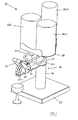
- FIG. 1 and 2 is illustrated a mixing device for beverages generally indicated with 10.
- the device 10 comprises a support 20 which in turn comprises a base 22 on which a first stem 24 is fixed and above it a second stem 26 is fixed.
- a support plate 28 is fixed at the free end of the second stem 26 and, above it, three containers 30a,30b,30c are mounted which are filled with beverages of different type depending on the desired mixed beverage. From each container 30a,30b,30c respectively starts a first, a second and a third delivery duct 32a,32b,32c made of deformable and elastic material such as rubber or the like.
- the delivery ducts 32a,32b,32c by applying a pressing force on the delivery ducts 32a,32b,32c, these are deformed or better yet they are compressed so reducing the passage cross-section of the liquid, while removing the pressing force, the ducts tend to return to their original position due to the elasticity of the material and, thus, the passage cross-section returns to the original one or, at least, to a cross-section very near to the initial one.
- An elongated plate 33 is mounted between the first stem 24 and the second stem 26, at the free end 33a of which holes 34a,34b,34c are formed in which the free ends of the delivery ducts 32a,32b,32c are respectively inserted.
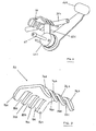
- Shutting means 40 are mounted on the elongated plate 33 for adjusting the amount of liquid delivered by each of the three delivery ducts 32a,32b,32c.
- the first and second cam 46a,46b are fixed to the first manoeuvring lever 44a through a first rod 48a offset with respect to the pin 42, while the third cam 46c is fixed to the second manoeuvring lever 44b by means of a second rod 48b also offset with respect to the pin 42. So, the first manoeuvring lever 44a rotates the first and second cam 46a, 46b, while the second manoeuvring lever 44b rotates the third cam 46c.
- antifriction spacers 50 are interposed between the cams 46a,46b,46c, and also between the manoeuvring levers 44a,44b and the cams 46a,46c.
- a first, second and third through hole 62a,62b,62c are respectively formed on the cylindrical support 60 at the first, second, third cam 46a,46b,46c.
- the pistons 64a,64b,64c have a cylindrical shape and their ends pressing against the delivery ducts are flat.
- the pistons could have other shapes, as well as their ends could be for example a cusp-shaped or spherical.
- the shutting means 40 also comprise an abutment element 70 (see figures 6 and 7 ) fixed on the cylindrical support 60 by means of screws 71a,71b.
- the abutment element 70 has a double comb shape, namely a plate 72 provided with four prongs 74a,b,c,d on one side, and with four additional prongs 76a,b,c,d on the opposite side, so as to form three recesses 78a,b,c on one side and other three recesses 80a,b,c on the opposite side, so that the first delivery duct 32a is inserted inside the recesses 78a,80a, the second delivery duct 32b is inserted inside the recesses 78b,80b and, finally, the third delivery duct 32c is inserted inside the recesses 78c, 80c. Therefore, each delivery duct 32a,32b,32c is interposed between the abutment element 70 and respectively one of the three pistons 64a,64b,64c.
- the operation of the device 10 occurs in the following manner.
- the third cam 46c rotates so the profile of the cam, at the third through hole 62c, moves away from the inside profile of the cylindrical support 60 and, then, the third piston 64c is lowered since the third delivery duct 32c tends to return to its original position due to the elasticity of the material of the duct, as described above, and also due to the weight of the piston 64c.
- the latter pushes less and less against the third delivery duct 32c. In this way, the inside passage cross-section of the ducts is no longer closed, but opens more and more as the second manoeuvring lever 44b is lowered.
- the first and second cam 46a, 46b do not push or they push only partially against the first and second piston 64a,64b and then against the first and second delivery duct 32a,32b, the passage cross-section of the ducts have the maximum opening permitted by the first and second cam 46a, 46b and the liquid is free to flow and come out.
- Each cam 46a,46b,46c is shaped according on the type of mixed drink to be made. In particular, if the dosage for each of the three beverages is the same, the three cams will be made with the same profile. If instead the dosages of the beverages are different, then the profiles of the cams will be different and made according to the required dosages.
- the mixed drink is always the same.
- the intensity of the output flow is increased and, therefore, the preparation time of the final drink is reduced but the composition remains always the same.
- the device may also be composed of only two containers 30a,30b and the first manoeuvring lever 44b operating on the first and second cam 46a,46b.
- cams 46a,46b,46c directly act on the respective delivery ducts 32a,32b,32c, therefore there is no need to use the pistons 64a,64b,64c.
- the device may be provided with means for cooling and/or heating means in order to obtain a mixed cold and/or hot drink.
- the pistons 64a, 64b, 64c may also be oriented downwards instead of upwards, or rather the pistons may be arranged below the cams 46a,46b,46c. In this case, starting from the condition in which the pistons are lowered and compress the delivery ducts, due to the rotation of the cams, the pistons are raised only because of the elastic return of the material of the ducts, as above explained.
- motor means for operating the pressing elements or pistons 64a,64b,64c As an alternative to the manual operation, it is possible to have motor means for operating the pressing elements or pistons 64a,64b,64c.
- motor means for operating the pressing elements or pistons 64a,64b,64c For example, instead of the manoeuvring levers, it is possible to use electric, pneumatic or idraulic actuators.
Landscapes
- Engineering & Computer Science (AREA)
- Mechanical Engineering (AREA)
- Mixers Of The Rotary Stirring Type (AREA)
- Devices For Dispensing Beverages (AREA)
Applications Claiming Priority (1)
| Application Number | Priority Date | Filing Date | Title |
|---|---|---|---|
| IT000009A ITVE20120009A1 (it) | 2012-03-07 | 2012-03-07 | Dispositivo miscelatore di liquidi. |
Publications (1)
| Publication Number | Publication Date |
|---|---|
| EP2636639A1 true EP2636639A1 (de) | 2013-09-11 |
Family
ID=46001589
Family Applications (1)
| Application Number | Title | Priority Date | Filing Date |
|---|---|---|---|
| EP13425037.2A Withdrawn EP2636639A1 (de) | 2012-03-07 | 2013-03-06 | Mischvorrichtung von Getränken |
Country Status (2)
| Country | Link |
|---|---|
| EP (1) | EP2636639A1 (de) |
| IT (1) | ITVE20120009A1 (de) |
Cited By (3)
| Publication number | Priority date | Publication date | Assignee | Title |
|---|---|---|---|---|
| GB2470660B (en) * | 2009-05-29 | 2015-09-16 | Imi Cornelius Uk Ltd | Apparatus for producing a beverage |
| CN110257210A (zh) * | 2019-07-18 | 2019-09-20 | 河北工业大学 | 一种鸡尾酒调制装置 |
| IT202300002430A1 (it) * | 2023-02-13 | 2024-08-13 | Sprizzer Srl | Dispositivo per l’erogazione di bevande |
Citations (10)
| Publication number | Priority date | Publication date | Assignee | Title |
|---|---|---|---|---|
| US4303222A (en) * | 1980-02-06 | 1981-12-01 | Red Valve Company, Inc. | Pinch valve |
| US4474214A (en) * | 1982-09-02 | 1984-10-02 | Iannelli Frank M | Beverage mixing and dispensing valve |
| CA1179992A (en) * | 1984-02-13 | 1984-12-27 | Bell, Michael | Milk dispenser |
| US4801050A (en) * | 1987-03-23 | 1989-01-31 | Michael Bell | Outlet tube restrictor |
| GB2274326A (en) * | 1993-01-18 | 1994-07-20 | Kodak Ltd | Pinch valve with adjustable reaction member |
| GB2275912A (en) * | 1993-03-11 | 1994-09-14 | P & O Vending Services Limited | Flow control valve for a drink dispenser |
| US5855298A (en) * | 1994-08-18 | 1999-01-05 | Creamiser Products Corporation | Tapping stem for liquid supply container |
| US5901745A (en) * | 1997-06-19 | 1999-05-11 | The Hoover Company | Multi-solution dispensing valve |
| DE20119454U1 (de) * | 2001-11-29 | 2002-02-14 | Aqua Vital Quell- und Mineralwasser GmbH, 41468 Neuss | Getränkeausgabegerät |
| EP1445234A1 (de) * | 2003-02-04 | 2004-08-11 | Conserve Italia Soc. Coop. A.R.L. | Vorrichtung zur Abgabe von Getränken |
-
2012
- 2012-03-07 IT IT000009A patent/ITVE20120009A1/it unknown
-
2013
- 2013-03-06 EP EP13425037.2A patent/EP2636639A1/de not_active Withdrawn
Patent Citations (10)
| Publication number | Priority date | Publication date | Assignee | Title |
|---|---|---|---|---|
| US4303222A (en) * | 1980-02-06 | 1981-12-01 | Red Valve Company, Inc. | Pinch valve |
| US4474214A (en) * | 1982-09-02 | 1984-10-02 | Iannelli Frank M | Beverage mixing and dispensing valve |
| CA1179992A (en) * | 1984-02-13 | 1984-12-27 | Bell, Michael | Milk dispenser |
| US4801050A (en) * | 1987-03-23 | 1989-01-31 | Michael Bell | Outlet tube restrictor |
| GB2274326A (en) * | 1993-01-18 | 1994-07-20 | Kodak Ltd | Pinch valve with adjustable reaction member |
| GB2275912A (en) * | 1993-03-11 | 1994-09-14 | P & O Vending Services Limited | Flow control valve for a drink dispenser |
| US5855298A (en) * | 1994-08-18 | 1999-01-05 | Creamiser Products Corporation | Tapping stem for liquid supply container |
| US5901745A (en) * | 1997-06-19 | 1999-05-11 | The Hoover Company | Multi-solution dispensing valve |
| DE20119454U1 (de) * | 2001-11-29 | 2002-02-14 | Aqua Vital Quell- und Mineralwasser GmbH, 41468 Neuss | Getränkeausgabegerät |
| EP1445234A1 (de) * | 2003-02-04 | 2004-08-11 | Conserve Italia Soc. Coop. A.R.L. | Vorrichtung zur Abgabe von Getränken |
Cited By (5)
| Publication number | Priority date | Publication date | Assignee | Title |
|---|---|---|---|---|
| GB2470660B (en) * | 2009-05-29 | 2015-09-16 | Imi Cornelius Uk Ltd | Apparatus for producing a beverage |
| CN110257210A (zh) * | 2019-07-18 | 2019-09-20 | 河北工业大学 | 一种鸡尾酒调制装置 |
| CN110257210B (zh) * | 2019-07-18 | 2023-12-12 | 河北工业大学 | 一种鸡尾酒调制装置 |
| IT202300002430A1 (it) * | 2023-02-13 | 2024-08-13 | Sprizzer Srl | Dispositivo per l’erogazione di bevande |
| WO2024171054A1 (en) * | 2023-02-13 | 2024-08-22 | Sprizzer Srl | Device for dispensing beverages |
Also Published As
| Publication number | Publication date |
|---|---|
| ITVE20120009A1 (it) | 2013-09-08 |
Similar Documents
| Publication | Publication Date | Title |
|---|---|---|
| EP2636639A1 (de) | Mischvorrichtung von Getränken | |
| US20120298694A1 (en) | Metering dispenser | |
| US4228930A (en) | Dispensing pump | |
| US5400614A (en) | Frozen dessert apparatus | |
| JP2021020743A (ja) | 飲料分注システム | |
| EP2682193B1 (de) | Spender | |
| EP2925665B1 (de) | Getränkeausgabesystem | |
| CA2029973A1 (en) | Fluid food dispenser | |
| EP1607700A3 (de) | Wasserspender mit Dosierung für einen Gefrierschrank | |
| JP2013508021A (ja) | オンデマンド式アイスティーのためのシステムおよび方法 | |
| CA2784875C (en) | Beverage-preparation device provided with a liquid distributor | |
| US20080185385A1 (en) | Locking mechanism for the cover for a drink dispensing machine | |
| GB2313106A (en) | Serving wine | |
| GB2470660A (en) | Apparatus for consistently mixing and dispensing a beverage | |
| CN1973740B (zh) | 由用于自动制备和分配浓咖啡的多个分配组件构成的设备 | |
| AT389865B (de) | Ausgabevorrichtung | |
| EP2039650A1 (de) | Ausschankvorrichtung für mehrere Getränke | |
| EP0339110B1 (de) | Getränkespendeautomat | |
| EP2039649A1 (de) | Ausschankvorrichtung mit Dosierpumpe für nachträglich gemischte Getränke | |
| CN220641736U (zh) | 一种便于配料的冰粉生产装置 | |
| CN223561266U (zh) | 椰子水生产用冷灌装生产机构 | |
| US1681866A (en) | Dispensing pump | |
| DE1532658B (de) | Getrankespender zum Ausschank von Mischgetränken | |
| EP1494960A2 (de) | Dispensor f r fl ssige lebensmittel | |
| WO2024171054A1 (en) | Device for dispensing beverages |
Legal Events
| Date | Code | Title | Description |
|---|---|---|---|
| PUAI | Public reference made under article 153(3) epc to a published international application that has entered the european phase |
Free format text: ORIGINAL CODE: 0009012 |
|
| AK | Designated contracting states |
Kind code of ref document: A1 Designated state(s): AL AT BE BG CH CY CZ DE DK EE ES FI FR GB GR HR HU IE IS IT LI LT LU LV MC MK MT NL NO PL PT RO RS SE SI SK SM TR |
|
| AX | Request for extension of the european patent |
Extension state: BA ME |
|
| STAA | Information on the status of an ep patent application or granted ep patent |
Free format text: STATUS: THE APPLICATION IS DEEMED TO BE WITHDRAWN |
|
| 18D | Application deemed to be withdrawn |
Effective date: 20140312 |