EP2636643A1 - Verfahren zur Herstellung einer pyrolytischen Graphitfolie und damit hergestellte pyrolytische Graphitfolie - Google Patents
Verfahren zur Herstellung einer pyrolytischen Graphitfolie und damit hergestellte pyrolytische Graphitfolie Download PDFInfo
- Publication number
- EP2636643A1 EP2636643A1 EP12158250.6A EP12158250A EP2636643A1 EP 2636643 A1 EP2636643 A1 EP 2636643A1 EP 12158250 A EP12158250 A EP 12158250A EP 2636643 A1 EP2636643 A1 EP 2636643A1
- Authority
- EP
- European Patent Office
- Prior art keywords
- raw material
- films
- film
- pyrolytic graphite
- container
- Prior art date
- Legal status (The legal status is an assumption and is not a legal conclusion. Google has not performed a legal analysis and makes no representation as to the accuracy of the status listed.)
- Withdrawn
Links
- OKTJSMMVPCPJKN-UHFFFAOYSA-N Carbon Chemical compound [C] OKTJSMMVPCPJKN-UHFFFAOYSA-N 0.000 title claims abstract description 65
- 229910002804 graphite Inorganic materials 0.000 title claims abstract description 65
- 239000010439 graphite Substances 0.000 title claims abstract description 65
- 238000000034 method Methods 0.000 title claims abstract description 51
- 239000002994 raw material Substances 0.000 claims abstract description 83
- 238000010438 heat treatment Methods 0.000 claims abstract description 33
- 229920006254 polymer film Polymers 0.000 claims abstract description 15
- 229920002577 polybenzoxazole Polymers 0.000 claims description 18
- 229920000553 poly(phenylenevinylene) Polymers 0.000 claims description 9
- 238000013022 venting Methods 0.000 claims description 9
- -1 poly (p-phenylene vinylene) Polymers 0.000 claims description 6
- 239000004952 Polyamide Substances 0.000 claims description 4
- 239000004642 Polyimide Substances 0.000 claims description 4
- 229920002647 polyamide Polymers 0.000 claims description 4
- 229920001721 polyimide Polymers 0.000 claims description 4
- 238000005096 rolling process Methods 0.000 claims description 3
- HYZJCKYKOHLVJF-UHFFFAOYSA-N 1H-benzimidazole Chemical compound C1=CC=C2NC=NC2=C1 HYZJCKYKOHLVJF-UHFFFAOYSA-N 0.000 claims description 2
- 230000009466 transformation Effects 0.000 abstract description 5
- 238000003763 carbonization Methods 0.000 abstract description 3
- 230000002269 spontaneous effect Effects 0.000 abstract description 3
- 239000006260 foam Substances 0.000 description 7
- 239000000463 material Substances 0.000 description 7
- 239000007789 gas Substances 0.000 description 6
- 239000011261 inert gas Substances 0.000 description 5
- 238000001816 cooling Methods 0.000 description 3
- 238000004519 manufacturing process Methods 0.000 description 3
- 238000012986 modification Methods 0.000 description 3
- 230000004048 modification Effects 0.000 description 3
- 238000012360 testing method Methods 0.000 description 3
- 239000004954 Polyphthalamide Substances 0.000 description 2
- 238000007796 conventional method Methods 0.000 description 2
- 238000010586 diagram Methods 0.000 description 2
- 238000005485 electric heating Methods 0.000 description 2
- 229920006375 polyphtalamide Polymers 0.000 description 2
- 230000018199 S phase Effects 0.000 description 1
- 238000007792 addition Methods 0.000 description 1
- XAGFODPZIPBFFR-UHFFFAOYSA-N aluminium Chemical compound [Al] XAGFODPZIPBFFR-UHFFFAOYSA-N 0.000 description 1
- 229910052782 aluminium Inorganic materials 0.000 description 1
- 125000003118 aryl group Chemical group 0.000 description 1
- 229910052799 carbon Inorganic materials 0.000 description 1
- 230000005611 electricity Effects 0.000 description 1
- 239000007770 graphite material Substances 0.000 description 1
- 238000005087 graphitization Methods 0.000 description 1
- 230000005484 gravity Effects 0.000 description 1
- 150000003949 imides Chemical class 0.000 description 1
- 229920013617 polymethylmethyacrylimide Polymers 0.000 description 1
- 238000006467 substitution reaction Methods 0.000 description 1
- 238000012546 transfer Methods 0.000 description 1
Images


Classifications
-
- C—CHEMISTRY; METALLURGY
- C04—CEMENTS; CONCRETE; ARTIFICIAL STONE; CERAMICS; REFRACTORIES
- C04B—LIME, MAGNESIA; SLAG; CEMENTS; COMPOSITIONS THEREOF, e.g. MORTARS, CONCRETE OR LIKE BUILDING MATERIALS; ARTIFICIAL STONE; CERAMICS; REFRACTORIES; TREATMENT OF NATURAL STONE
- C04B35/00—Shaped ceramic products characterised by their composition; Ceramics compositions; Processing powders of inorganic compounds preparatory to the manufacturing of ceramic products
- C04B35/515—Shaped ceramic products characterised by their composition; Ceramics compositions; Processing powders of inorganic compounds preparatory to the manufacturing of ceramic products based on non-oxide ceramics
- C04B35/52—Shaped ceramic products characterised by their composition; Ceramics compositions; Processing powders of inorganic compounds preparatory to the manufacturing of ceramic products based on non-oxide ceramics based on carbon, e.g. graphite
- C04B35/524—Shaped ceramic products characterised by their composition; Ceramics compositions; Processing powders of inorganic compounds preparatory to the manufacturing of ceramic products based on non-oxide ceramics based on carbon, e.g. graphite obtained from polymer precursors, e.g. glass-like carbon material
-
- C—CHEMISTRY; METALLURGY
- C01—INORGANIC CHEMISTRY
- C01B—NON-METALLIC ELEMENTS; COMPOUNDS THEREOF; METALLOIDS OR COMPOUNDS THEREOF NOT COVERED BY SUBCLASS C01C
- C01B32/00—Carbon; Compounds thereof
- C01B32/20—Graphite
- C01B32/205—Preparation
Definitions
- the present invention relates to a method for fabricating a pyrolytic graphite material, and particularly relates to a method for fabricating a pyrolytic graphite film by using a polymer film as the raw material and to the pyrolytic graphite film fabricated thereby.
- a pyrolytic graphite thermal conductive film As a new type of high-performance thermally conductive interface material, a pyrolytic graphite thermal conductive film has an extensive application prospect in IT products (including smart cell phones, writing pads, notebook computers, servers, vehicle controllers, etc.) and electronic devices which need high thermal conductivity due to the excellent thermal conductivity coefficient (1500w/mk) on the surface, which is 5 to 7 times higher than the thermal conductivity coefficient of aluminum.
- a heating device heats the gas in a heat furnace to form a high temperature atmosphere, and the raw material film is heated in such high temperature atmosphere. There is no direct contact between the raw material film and the heating circuit.
- the other method is the electric heating method. The heating device heats the gas in the furnace; because the raw material film is a part of the heating circuit, the heating electricity flows through the raw material film, contacts and heats the raw material film directly.
- a method for fabricating a pyrolytic graphite film is disclosed in patent document JP-A No. S61-275116 .
- the method uses a polymer film such as p-POD (p-polyoxadiazole), PBT (polybenzothiazole), PBBT (polybenzobisthiazole), PBO (polybenzoxazole), PBBO (polybenzobisoxazole), or PT (polythiazole) as the raw material film and utilizes the atmospheric heating method in which, under vacuum or in an inert gas applying a tensile force, a preheat treatment is performed in a temperature range of 400°C - 700°C, and the heat treatment is performed when the temperature is higher than 1600°C, so that a high purity pyrolytic graphite film can be fabricated.
- p-POD p-polyoxadiazole
- PBT polybenzothiazole
- PBBT polybenzobisthiazole
- PBO
- the heat treatment is first performed at a minimum temperature of 1600 °C or above on at least one of the polymer films including POD (polybenzoxadiazole), PBT, PBBT, PBO, PBBO, PMMI (poly(pyromellitic imide)), PPA (polyphthalamide), PBI (polybenzoimidazole), PBBI (polybenzobisimidazole), PT, PPV (poly(p-phenylene vinylene)), etc., and the heat treatment is then performed when the temperature is higher than 2400°C.
- an isotropic pressure in a specified temperature range is added to control the foam state of the pyrolytic graphite film, and then perform a rolling press on the pyrolytic graphite film to obtain the better softness and flexibility property.
- the raw material transforms into the pyrolytic graphite film by a high-temperature (higher than 1600°C) phase transformation.
- the key indicators of the pyrolytic graphite film are thermal conductivity, flatness and softness.
- the thermal conductivity is directly associated with the level of the raw material film's phase transformation.
- the flatness is closely associated with the raw material film's torsion resistance, and the softness is closely related to the foam size of the surfaces of the pyrolytic graphite film.
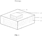
- the atmosphere heating method at present includes a container 11, a raw material film 12 and a block 13.
- a container 11 In order to increase production, multiple layers of raw material films 12 are overlaid, and are placed into the container 11 horizontally.
- a pressure is needed to put vertically on the raw material film 12. As shown in the FIG. 1 , a weight block 13 is placed on the raw material film 12 to avoid the tortuosity during the transformation in the high temperature. The more layers there are, the more pressure is needed.
- a method of fabricating the pyrolytic graphite film and the pyrolytic graphite film fabricated thereby are provided in the present invention for keeping spontaneous spaces among the multiple layers of raw material films to solve the problem of uneven thermal conductivity of the pyrolytic graphite film.
- a method for fabricating a pyrolytic graphite film uses a polymer film as the raw material film, overlays multiple layers of raw material films, places the overlaid raw material films into a container, and performs heat treatment on the multiple layers of raw material films which are in a vertical state to obtain the pyrolytic graphite films.
- the raw material films are placed into the container horizontally, the container is overturned so that the raw materials are in the vertical state.
- an opening for placing and fetching the raw material films is set on a face of the container.
- the opening fully opens the face in which it is set.
- the opening is set on the top of the container when the raw material films are in the vertical state.
- the opening is set in a face of the container that is vertical during heat treatment.
- one of the container's faces which is perpendicular to the raw material films can be fully opened.
- the opening is closed by a lid during heat treatment.
- the lid can be fixed on said container by a lock component. This is of particular interest when the container's face with the opening is parallel to the raw material films and can be fully opened.
- a plurality of venting holes are on the surface of the container.
- the polymer film comprises at least one of the films selected from the group of POD (polybenzoxadiazole), PI (polyimide), PPV (poly (p-phenylene vinylene)), PBI (poly benzoimidazole), PBO (polybenzooxazole), PBBO (polybenzobisoxazole), PT (polythiazole), PBT (Polybenzothiazole), PBBT (polybenzobisthiazole), and PA (polyamide).
- POD polybenzoxadiazole
- PI polyimide
- PPV poly (p-phenylene vinylene)
- PBI poly benzoimidazole
- PBO polybenzooxazole
- PBBO polybenzobisoxazole
- PT polythiazole
- PBT Polybenzothiazole
- PBBT polybenzobisthiazole
- PA polyamide
- rolling press is performed on the pyrolytic graphite film after the heat treatment.
- the fabricated pyrolytic graphite film is obtained through the method as disclosed above.
- a method for fabricating a pyrolytic graphite film and the pyrolytic graphite film fabricated thereby are provided in the present invention.
- the method uses a polymer film as a raw material film, overlays multiple layers of raw material films and places the overlaid raw material films into a container.
- the raw material films are in the vertical state to keep spontaneous spaces among the multiple layers of raw material films.
- the pyrolytic graphite film fabricated by this method has less tortuosity, more increased surface thermal conductivity and more even thermal conductivity.
- FIG. 1 shows a diagram of a container with filled materials in a conventional way
- FIG. 2 shows a diagram of a container with filled materials, in accordance with one embodiment of the present invention
- FIG. 3 shows a process of filling the materials in the container in accordance with one preferred embodiment of the present invention.
- the present invention uses a polymer film as a raw material film, overlays multiple layers of raw material films, places the overlaid raw material films into a container and performs heat treatment on the multiple layers of raw material films which are in a vertical state to obtain the pyrolytic graphite films.
- the polymer films that can be used in the present invention include POD (polybenzoxadiazole), PI (polyimide), PPV (poly (p-phenylene vinylene)), PBI (polybenzoimidazole), PBO (polybenzoxazole), PBBO (polybenzobisoxazole), PT (polythiazole), PBT (Polybenzothiazole), PBBT (polybenzobisthiazole), and PA (polyamide), At least one of the heat resistant aromatic polymer films as mentioned above can be preferably selected. These polymer films can be fabricated by a publicly known method. Moreover, compared with other polymer films, PI is much easier to carbonize and graphitize, so that a pyrolytic graphite film of excellent crystalline and thermal conductivity can be formed.
- the raw material films are filled in the spaces of two surfaces which are parallel to the films in the container, so that the raw material films are in a vertical state during the process of heat treatment. If the raw material films cannot be kept vertical, high heat resist material like graphite can be selected instead to be overlaid with the raw material films and be filled in the spaces of two surfaces which are parallel to the films in the container.
- An opening is set on at least one face of the container for placing and fetching the films.
- the size of the opening is not limited, as long as the raw material films can be placed into or fetched from the container through the opening.
- the opening is set on the top of the container when the films are in the vertical state.
- the opening should be fully opened.
- a face which is perpendicular to the films can be fully opened.
- the raw material films are placed into the furnace as shown in FIG. 2 , in which a container 21 and the raw material films 22 are shown.
- the container is initially placed in the orientation shown in FIG. 3 (a) , where the opened face B of the container is vertical, that is perpendicular to the horizontal plane.
- Multiple layers of raw material films are horizontally placed into the container via the opening of face B.
- the container filled with the raw material films is pricked up with the opened face B upward, as shown in FIG. 3 (b) , so that the raw material films are put in the vertical state.
- a lid can be put to close the face B, or the face B can remain open. If the films can be placed the container smoothly without performing the step shown in FIG. 3(a) , then that step can be dispensed, and the raw material films can be directly placed vertically into the container as shown in FIG. 2 through the opening of face B.
- a face parallel to the films can be used for placing the raw material films, as the face C shown in FIG. 2 .
- This face can be fully opened to place and fetch the films.
- a lock component is advantageously provided to close the face C of the container. More precisely, after the material is filled into the container, the lock is used to fix a lid so as to close the face C, in case of risks for the film to slide during the process of heat treatment.
- a plurality of venting holes are set on the surface of the container, so that the high temperature gas can flow freely.
- a plurality of holes are set at least on the surface of the container vertical to the films for venting. More preferably, a plurality of venting holes are set on each of the surfaces of the container.
- venting holes care should be taken for choosing the right size of venting holes. If the size of venting hole is too large, there may be a big ripple on the film transfer surface, or the pyrolytic graphite film may be broken if hooked by the venting hole.
- the area of the hole is set as large as possible under the condition that the risk for a ripple to be transferred onto the film be minimum, and a risk for the film to break be avoided.
- the diameter of the hole is less than 10mm.
- the shape of the hole compared with the quadrangle, a hole of round shape is less likely to hook the film, which is preferred.
- the raw material films are preheated and also heated at high temperature.
- the raw material films are heat preserved for an hour in an inert gas under a normal pressure or elevated pressure under a temperature in the range of 400 ⁇ 1200°C.
- the raw material films are heat preserved under the temperature in the range of 1200 ⁇ 3200°C for an hour, and eventually, heat treated when the temperature is greater than 2400°C.
- the foamed pyrolytic graphite films are fetched. Eventually, the pyrolytic graphite films are pressed.
- the weight of the raw material films could be reduced due to the carbonization, and the thickness is thinner, and the spaces can be spontaneously formed among the overlaid raw material films to provide a channel for the high temperature gas.
- the constricted films are spontaneously aligned at the bottom due to the gravity, so that the sliding among the films and the uncontrollable tortuosity caused by the incline or dislocation sliding can be avoided, thus, the pyrolytic graphite film can be evenly heat treated and can thus have an even thermal conductivity.
- the two surfaces which are parallel to the films play a role of position-restriction which has a vertical pressure on the foam and tortuosity. Because the position-restriction acts evenly on all the raw material films, the over-sized foam and uneven foam can be avoided, and the softness of the pyrolytic graphite film is improved.
- 500 sheets PI films with the size of 200mm ⁇ 300mm and the thickness of 0.125mm are vertically placed into the container, as shown in the FIG. 2 .
- the films are heat preserved at a temperature range of 400 ⁇ 1200°C in an inert gas for an hour. Then, the films are heat preserved at the temperature range of 1200 ⁇ 3200°C for an hour.
- the foamed pyrolytic graphite films are fetched. The tortuous pyrolytic graphite films are picked out, and their number is recorded. The rest of the pyrolytic graphite films are pressed.
- the first fabricated pyrolytic graphite film, the hundredth fabricated pyrolytic graphite film, the two-hundredth fabricated pyrolytic graphite film, the three-hundredth fabricated pyrolytic graphite film and the three-hundred fiftieth fabricated pyrolytic graphite film are picked out to test the thermal conductivity within a surface.
- a conventional way of placement is used.
- 500 sheets PI films with the of 200mm ⁇ 300mm and the thickness of 0. 1 25mm are horizontally placed into the container.
- the films are parallel to the opened surface A of the container.
- a block 13 with the weight of 5KG is placed on the top of the overlaid raw material films to put a vertical pressure can the films, as show in the FIG. 1 .
- the films are heat preserved at a temperature range of 400 ⁇ 1200°C in an inert gas for an hour. Then the films are heat preserved at the temperature range of 1200 ⁇ 3200°C for an hour. After the films are cooling to the room temperature, the foamed pyrolytic graphite films are fetched.
- the tortuous pyrolytic graphite films are picked out, and their number is recorded. The rest of the pyrolytic graphite films are pressed.
- the first fabricated pyrolytic graphite film, the hundredth fabricated pyrolytic graphite film, the two-hundredth fabricated pyrolytic graphite film, the three-hundredth fabricated pyrolytic graphite film and the three-hundred fiftieth fabricated pyrolytic graphite film are picked out to test the thermal conductivity within a surface.
- test result can be shown in table 1: Table 1 Conventional Method Method provided in present invention Surface thermal conductivity (W/mK) Surface thermal conductivity (W/mK) The number of the tortuous pyrolytic graphite films among the 500 sheets 25 0 No.1 700 920 No.100 650 930 No.200 620 926 No.300 650 935 No.350 700 934
Landscapes
- Chemical & Material Sciences (AREA)
- Organic Chemistry (AREA)
- Engineering & Computer Science (AREA)
- Life Sciences & Earth Sciences (AREA)
- General Life Sciences & Earth Sciences (AREA)
- Geology (AREA)
- Inorganic Chemistry (AREA)
- Ceramic Engineering (AREA)
- Manufacturing & Machinery (AREA)
- Materials Engineering (AREA)
- Structural Engineering (AREA)
- Carbon And Carbon Compounds (AREA)
Priority Applications (1)
| Application Number | Priority Date | Filing Date | Title |
|---|---|---|---|
| EP12158250.6A EP2636643A1 (de) | 2012-03-06 | 2012-03-06 | Verfahren zur Herstellung einer pyrolytischen Graphitfolie und damit hergestellte pyrolytische Graphitfolie |
Applications Claiming Priority (1)
| Application Number | Priority Date | Filing Date | Title |
|---|---|---|---|
| EP12158250.6A EP2636643A1 (de) | 2012-03-06 | 2012-03-06 | Verfahren zur Herstellung einer pyrolytischen Graphitfolie und damit hergestellte pyrolytische Graphitfolie |
Publications (1)
| Publication Number | Publication Date |
|---|---|
| EP2636643A1 true EP2636643A1 (de) | 2013-09-11 |
Family
ID=45819035
Family Applications (1)
| Application Number | Title | Priority Date | Filing Date |
|---|---|---|---|
| EP12158250.6A Withdrawn EP2636643A1 (de) | 2012-03-06 | 2012-03-06 | Verfahren zur Herstellung einer pyrolytischen Graphitfolie und damit hergestellte pyrolytische Graphitfolie |
Country Status (1)
| Country | Link |
|---|---|
| EP (1) | EP2636643A1 (de) |
Cited By (3)
| Publication number | Priority date | Publication date | Assignee | Title |
|---|---|---|---|---|
| CN105692603A (zh) * | 2016-03-14 | 2016-06-22 | 苏州金禾新材料股份有限公司 | 一种导热石墨膜的制备方法及一种石墨坩埚 |
| WO2017183705A1 (ja) * | 2016-04-22 | 2017-10-26 | 株式会社カネカ | 高配向性グラファイト、および、高配向性グラファイトの製造方法 |
| US10262916B2 (en) * | 2016-12-20 | 2019-04-16 | Jones Tech Inc. | Foldable graphite heat spreader |
Citations (8)
| Publication number | Priority date | Publication date | Assignee | Title |
|---|---|---|---|---|
| JPS60126324A (ja) * | 1983-12-07 | 1985-07-05 | Nippon Steel Corp | フィラメントの揃いの良い炭素繊維束を製造する方法 |
| JPS61275116A (ja) | 1985-05-30 | 1986-12-05 | Res Dev Corp Of Japan | グラフアイトフイルムおよび繊維の製造方法 |
| JPH01203280A (ja) * | 1988-02-09 | 1989-08-16 | Sumitomo Metal Ind Ltd | 多孔質炭素材料の製造方法 |
| JPH0375211A (ja) | 1989-05-10 | 1991-03-29 | Matsushita Electric Ind Co Ltd | フィルム状グラファイトの製造方法 |
| JP2004299937A (ja) * | 2003-03-28 | 2004-10-28 | Kanegafuchi Chem Ind Co Ltd | グラファイトフィルムの製造方法 |
| WO2010150300A1 (ja) * | 2009-06-22 | 2010-12-29 | 株式会社カネカ | グラファイトフィルムおよびグラファイトフィルムの製造方法 |
| US20110165379A1 (en) | 2007-05-17 | 2011-07-07 | Kaneka Corporation | Graphite Film and Graphite Composite Film |
| US20110169180A1 (en) * | 2008-09-11 | 2011-07-14 | Takashi Inada | Method for manufacturing carbonaceous film, and graphite film obtained thereby |
-
2012
- 2012-03-06 EP EP12158250.6A patent/EP2636643A1/de not_active Withdrawn
Patent Citations (8)
| Publication number | Priority date | Publication date | Assignee | Title |
|---|---|---|---|---|
| JPS60126324A (ja) * | 1983-12-07 | 1985-07-05 | Nippon Steel Corp | フィラメントの揃いの良い炭素繊維束を製造する方法 |
| JPS61275116A (ja) | 1985-05-30 | 1986-12-05 | Res Dev Corp Of Japan | グラフアイトフイルムおよび繊維の製造方法 |
| JPH01203280A (ja) * | 1988-02-09 | 1989-08-16 | Sumitomo Metal Ind Ltd | 多孔質炭素材料の製造方法 |
| JPH0375211A (ja) | 1989-05-10 | 1991-03-29 | Matsushita Electric Ind Co Ltd | フィルム状グラファイトの製造方法 |
| JP2004299937A (ja) * | 2003-03-28 | 2004-10-28 | Kanegafuchi Chem Ind Co Ltd | グラファイトフィルムの製造方法 |
| US20110165379A1 (en) | 2007-05-17 | 2011-07-07 | Kaneka Corporation | Graphite Film and Graphite Composite Film |
| US20110169180A1 (en) * | 2008-09-11 | 2011-07-14 | Takashi Inada | Method for manufacturing carbonaceous film, and graphite film obtained thereby |
| WO2010150300A1 (ja) * | 2009-06-22 | 2010-12-29 | 株式会社カネカ | グラファイトフィルムおよびグラファイトフィルムの製造方法 |
Cited By (4)
| Publication number | Priority date | Publication date | Assignee | Title |
|---|---|---|---|---|
| CN105692603A (zh) * | 2016-03-14 | 2016-06-22 | 苏州金禾新材料股份有限公司 | 一种导热石墨膜的制备方法及一种石墨坩埚 |
| WO2017183705A1 (ja) * | 2016-04-22 | 2017-10-26 | 株式会社カネカ | 高配向性グラファイト、および、高配向性グラファイトの製造方法 |
| JPWO2017183705A1 (ja) * | 2016-04-22 | 2019-01-31 | 株式会社カネカ | 高配向性グラファイト、および、高配向性グラファイトの製造方法 |
| US10262916B2 (en) * | 2016-12-20 | 2019-04-16 | Jones Tech Inc. | Foldable graphite heat spreader |
Similar Documents
| Publication | Publication Date | Title |
|---|---|---|
| Rolston et al. | Engineering stress in perovskite solar cells to improve stability | |
| CN103864068B (zh) | 一种高导热石墨膜的制备方法 | |
| CN103043657A (zh) | 胶带用石墨散热片 | |
| JP2012012297A (ja) | グラファイトフィルム | |
| CN103547530B (zh) | 石墨膜的制造方法及碳化膜的制造方法 | |
| CN102745674A (zh) | 片状石墨膜的制造模具及制造方法 | |
| EP2636643A1 (de) | Verfahren zur Herstellung einer pyrolytischen Graphitfolie und damit hergestellte pyrolytische Graphitfolie | |
| US20200156948A1 (en) | Graphite article | |
| JP6030620B2 (ja) | ポリアミド−イミド、グラファイトフィルム、およびグラファイトフィルムの作製 | |
| KR101952997B1 (ko) | 그라파이트 플레이트 및 그 제조 방법 | |
| KR20110083250A (ko) | 세라믹 제품용 소성로 및 이를 이용한 소성방법 | |
| CN105483624A (zh) | 钼硅靶材及其组合的制造方法 | |
| Kang et al. | Thermal shock fabrication of ion‐stabilized perovskite and solar cells | |
| KR20160116366A (ko) | 열전도도가 우수한 그라파이트 시트의 제조방법 및 이로 제조된 그라파이트 시트 | |
| US20180127561A1 (en) | Fabrication of a graphite film based on a polyimide film | |
| JP5306410B2 (ja) | グラファイトフィルムおよびグラファイトフィルムの製造方法 | |
| CN106348287B (zh) | 石墨片及其制造方法 | |
| Hadik et al. | Dielectric behavior of ceramic (BST)/epoxy thick films | |
| US20170320740A1 (en) | Graphite plate and production method thereof | |
| JP5573533B2 (ja) | 基板の熱処理方法および熱処理装置 | |
| CN106433500A (zh) | 用于电子产品的压敏胶带 | |
| CN108218428A (zh) | 用于平板电脑均热贴片的制造方法 | |
| JP2004356355A (ja) | 熱処理方法、基板の製造方法、半導体装置の製造方法及び熱処理装置 | |
| JPH0517117A (ja) | グラフアイトの製造方法 | |
| WO2014134791A1 (zh) | 导热垫片及其应用 |
Legal Events
| Date | Code | Title | Description |
|---|---|---|---|
| PUAI | Public reference made under article 153(3) epc to a published international application that has entered the european phase |
Free format text: ORIGINAL CODE: 0009012 |
|
| AK | Designated contracting states |
Kind code of ref document: A1 Designated state(s): AL AT BE BG CH CY CZ DE DK EE ES FI FR GB GR HR HU IE IS IT LI LT LU LV MC MK MT NL NO PL PT RO RS SE SI SK SM TR |
|
| AX | Request for extension of the european patent |
Extension state: BA ME |
|
| RAP1 | Party data changed (applicant data changed or rights of an application transferred) |
Owner name: JONES TECH PLC |
|
| 17P | Request for examination filed |
Effective date: 20140311 |
|
| RBV | Designated contracting states (corrected) |
Designated state(s): AL AT BE BG CH CY CZ DE DK EE ES FI FR GB GR HR HU IE IS IT LI LT LU LV MC MK MT NL NO PL PT RO RS SE SI SK SM TR |
|
| 17Q | First examination report despatched |
Effective date: 20140414 |
|
| STAA | Information on the status of an ep patent application or granted ep patent |
Free format text: STATUS: THE APPLICATION IS DEEMED TO BE WITHDRAWN |
|
| 18D | Application deemed to be withdrawn |
Effective date: 20140826 |