EP2636721A1 - Gazéificateur de biomasse - Google Patents
Gazéificateur de biomasse Download PDFInfo
- Publication number
- EP2636721A1 EP2636721A1 EP13157744.7A EP13157744A EP2636721A1 EP 2636721 A1 EP2636721 A1 EP 2636721A1 EP 13157744 A EP13157744 A EP 13157744A EP 2636721 A1 EP2636721 A1 EP 2636721A1
- Authority
- EP
- European Patent Office
- Prior art keywords
- gasifier
- disruption device
- outer chamber
- disruption
- biomass
- Prior art date
- Legal status (The legal status is an assumption and is not a legal conclusion. Google has not performed a legal analysis and makes no representation as to the accuracy of the status listed.)
- Withdrawn
Links
Images


Classifications
-
- C—CHEMISTRY; METALLURGY
- C10—PETROLEUM, GAS OR COKE INDUSTRIES; TECHNICAL GASES CONTAINING CARBON MONOXIDE; FUELS; LUBRICANTS; PEAT
- C10J—PRODUCTION OF PRODUCER GAS, WATER-GAS, SYNTHESIS GAS FROM SOLID CARBONACEOUS MATERIAL, OR MIXTURES CONTAINING THESE GASES; CARBURETTING AIR OR OTHER GASES
- C10J3/00—Production of combustible gases containing carbon monoxide from solid carbonaceous fuels
- C10J3/02—Fixed-bed gasification of lump fuel
- C10J3/20—Apparatus; Plants
- C10J3/22—Arrangements or dispositions of valves or flues
- C10J3/24—Arrangements or dispositions of valves or flues to permit flow of gases or vapours other than upwardly through the fuel bed
- C10J3/26—Arrangements or dispositions of valves or flues to permit flow of gases or vapours other than upwardly through the fuel bed downwardly
-
- C—CHEMISTRY; METALLURGY
- C10—PETROLEUM, GAS OR COKE INDUSTRIES; TECHNICAL GASES CONTAINING CARBON MONOXIDE; FUELS; LUBRICANTS; PEAT
- C10J—PRODUCTION OF PRODUCER GAS, WATER-GAS, SYNTHESIS GAS FROM SOLID CARBONACEOUS MATERIAL, OR MIXTURES CONTAINING THESE GASES; CARBURETTING AIR OR OTHER GASES
- C10J3/00—Production of combustible gases containing carbon monoxide from solid carbonaceous fuels
- C10J3/02—Fixed-bed gasification of lump fuel
- C10J3/20—Apparatus; Plants
- C10J3/30—Fuel charging devices
-
- C—CHEMISTRY; METALLURGY
- C10—PETROLEUM, GAS OR COKE INDUSTRIES; TECHNICAL GASES CONTAINING CARBON MONOXIDE; FUELS; LUBRICANTS; PEAT
- C10J—PRODUCTION OF PRODUCER GAS, WATER-GAS, SYNTHESIS GAS FROM SOLID CARBONACEOUS MATERIAL, OR MIXTURES CONTAINING THESE GASES; CARBURETTING AIR OR OTHER GASES
- C10J3/00—Production of combustible gases containing carbon monoxide from solid carbonaceous fuels
- C10J3/02—Fixed-bed gasification of lump fuel
- C10J3/20—Apparatus; Plants
- C10J3/32—Devices for distributing fuel evenly over the bed or for stirring up the fuel bed
-
- C—CHEMISTRY; METALLURGY
- C10—PETROLEUM, GAS OR COKE INDUSTRIES; TECHNICAL GASES CONTAINING CARBON MONOXIDE; FUELS; LUBRICANTS; PEAT
- C10J—PRODUCTION OF PRODUCER GAS, WATER-GAS, SYNTHESIS GAS FROM SOLID CARBONACEOUS MATERIAL, OR MIXTURES CONTAINING THESE GASES; CARBURETTING AIR OR OTHER GASES
- C10J2200/00—Details of gasification apparatus
- C10J2200/15—Details of feeding means
- C10J2200/158—Screws
-
- C—CHEMISTRY; METALLURGY
- C10—PETROLEUM, GAS OR COKE INDUSTRIES; TECHNICAL GASES CONTAINING CARBON MONOXIDE; FUELS; LUBRICANTS; PEAT
- C10J—PRODUCTION OF PRODUCER GAS, WATER-GAS, SYNTHESIS GAS FROM SOLID CARBONACEOUS MATERIAL, OR MIXTURES CONTAINING THESE GASES; CARBURETTING AIR OR OTHER GASES
- C10J2200/00—Details of gasification apparatus
- C10J2200/36—Moving parts inside the gasification reactor not otherwise provided for
-
- C—CHEMISTRY; METALLURGY
- C10—PETROLEUM, GAS OR COKE INDUSTRIES; TECHNICAL GASES CONTAINING CARBON MONOXIDE; FUELS; LUBRICANTS; PEAT
- C10J—PRODUCTION OF PRODUCER GAS, WATER-GAS, SYNTHESIS GAS FROM SOLID CARBONACEOUS MATERIAL, OR MIXTURES CONTAINING THESE GASES; CARBURETTING AIR OR OTHER GASES
- C10J2300/00—Details of gasification processes
- C10J2300/09—Details of the feed, e.g. feeding of spent catalyst, inert gas or halogens
- C10J2300/0903—Feed preparation
- C10J2300/0906—Physical processes, e.g. shredding, comminuting, chopping, sorting
-
- C—CHEMISTRY; METALLURGY
- C10—PETROLEUM, GAS OR COKE INDUSTRIES; TECHNICAL GASES CONTAINING CARBON MONOXIDE; FUELS; LUBRICANTS; PEAT
- C10J—PRODUCTION OF PRODUCER GAS, WATER-GAS, SYNTHESIS GAS FROM SOLID CARBONACEOUS MATERIAL, OR MIXTURES CONTAINING THESE GASES; CARBURETTING AIR OR OTHER GASES
- C10J2300/00—Details of gasification processes
- C10J2300/09—Details of the feed, e.g. feeding of spent catalyst, inert gas or halogens
- C10J2300/0913—Carbonaceous raw material
- C10J2300/0916—Biomass
-
- C—CHEMISTRY; METALLURGY
- C10—PETROLEUM, GAS OR COKE INDUSTRIES; TECHNICAL GASES CONTAINING CARBON MONOXIDE; FUELS; LUBRICANTS; PEAT
- C10J—PRODUCTION OF PRODUCER GAS, WATER-GAS, SYNTHESIS GAS FROM SOLID CARBONACEOUS MATERIAL, OR MIXTURES CONTAINING THESE GASES; CARBURETTING AIR OR OTHER GASES
- C10J2300/00—Details of gasification processes
- C10J2300/09—Details of the feed, e.g. feeding of spent catalyst, inert gas or halogens
- C10J2300/0953—Gasifying agents
- C10J2300/0956—Air or oxygen enriched air
-
- C—CHEMISTRY; METALLURGY
- C10—PETROLEUM, GAS OR COKE INDUSTRIES; TECHNICAL GASES CONTAINING CARBON MONOXIDE; FUELS; LUBRICANTS; PEAT
- C10J—PRODUCTION OF PRODUCER GAS, WATER-GAS, SYNTHESIS GAS FROM SOLID CARBONACEOUS MATERIAL, OR MIXTURES CONTAINING THESE GASES; CARBURETTING AIR OR OTHER GASES
- C10J2300/00—Details of gasification processes
- C10J2300/16—Integration of gasification processes with another plant or parts within the plant
- C10J2300/164—Integration of gasification processes with another plant or parts within the plant with conversion of synthesis gas
- C10J2300/1643—Conversion of synthesis gas to energy
- C10J2300/165—Conversion of synthesis gas to energy integrated with a gas turbine or gas motor
-
- Y—GENERAL TAGGING OF NEW TECHNOLOGICAL DEVELOPMENTS; GENERAL TAGGING OF CROSS-SECTIONAL TECHNOLOGIES SPANNING OVER SEVERAL SECTIONS OF THE IPC; TECHNICAL SUBJECTS COVERED BY FORMER USPC CROSS-REFERENCE ART COLLECTIONS [XRACs] AND DIGESTS
- Y02—TECHNOLOGIES OR APPLICATIONS FOR MITIGATION OR ADAPTATION AGAINST CLIMATE CHANGE
- Y02E—REDUCTION OF GREENHOUSE GAS [GHG] EMISSIONS, RELATED TO ENERGY GENERATION, TRANSMISSION OR DISTRIBUTION
- Y02E20/00—Combustion technologies with mitigation potential
- Y02E20/16—Combined cycle power plant [CCPP], or combined cycle gas turbine [CCGT]
- Y02E20/18—Integrated gasification combined cycle [IGCC], e.g. combined with carbon capture and storage [CCS]
-
- Y—GENERAL TAGGING OF NEW TECHNOLOGICAL DEVELOPMENTS; GENERAL TAGGING OF CROSS-SECTIONAL TECHNOLOGIES SPANNING OVER SEVERAL SECTIONS OF THE IPC; TECHNICAL SUBJECTS COVERED BY FORMER USPC CROSS-REFERENCE ART COLLECTIONS [XRACs] AND DIGESTS
- Y02—TECHNOLOGIES OR APPLICATIONS FOR MITIGATION OR ADAPTATION AGAINST CLIMATE CHANGE
- Y02P—CLIMATE CHANGE MITIGATION TECHNOLOGIES IN THE PRODUCTION OR PROCESSING OF GOODS
- Y02P20/00—Technologies relating to chemical industry
- Y02P20/141—Feedstock
- Y02P20/145—Feedstock the feedstock being materials of biological origin
Definitions
- the present application and the resultant patent relate generally to power generation systems and more particularly relate to a gasifier with an internal disruption device so as to prevent the bridging of biomass and other types of feedstock materials therein.
- solid fuels such as wood, agricultural wastes, and the like
- gasification processes may convert a feedstock of biomass or other hydrocarbon into a gaseous mixture of carbon monoxide and hydrogen, i.e., a synthetic gas or a syngas referred to as a producer gas, by reaction with oxygen and steam in a gasifier. These gases then may be cleaned, processed, and utilized as a fuel in an engine to produce electricity.
- the producer gas may be used to generate power, to produce fuel for heating, or to generate chemical products such as Fisher Tropsch liquids and the like
- biomass feedstock materials tend to be fibrous. As such, the biomass feedstock materials may tend to bridge across the interior of a gasifier when fed therein. Such a biomass bridge, when formed, may reduce the flow of the feedstock materials into the reaction zone and thus may have an impact on the output of the producer gas in terms of composition and flow rate.
- One known method of reducing the bridging of feedstock materials in a gasifier involves an operator physically poking the bridge of feedstock materials with a pole.
- the need for operator intervention may expose the operator to higher than normal levels of reaction product gases as well as exposure to the hot surfaces of the gasifier.
- the need of operator intervention generally is not detected until there is some degradation in the overall performance of the gasifier.
- an improved biomass gasifier may prevent or limit the bridging of feedstock materials such as biomass materials so as to ensure a constant output of syngas without requiring manual operator intervention.
- the present application and the resultant patent thus may provide a gasifier for use in converting a feedstock material into a syngas.
- the gasifier may include an outer chamber, a reaction zone positioned within the outer chamber, and a disruption device maneuverable within the outer chamber to ensure a steady flow of the feedstock material into the reaction zone without bridging.
- the present application and the resultant patent further may provide a method of operating a gasifier to produce a syngas.
- the method may include the steps of flowing a feedstock material into an outer chamber of the gasifier, maneuvering a disruption device within the outer chamber to prevent the bridging of the feedstock material therein, and flowing the feedstock material into a reaction zone.
- the present application and the resultant patent further may provide a biomass gasifier for use in converting a feedstock material into a syngas.
- the biomass gasifier may include an outer chamber, a reaction zone positioned within the outer chamber, and a disruption device maneuverable within the outer chamber to ensure a steady flow of the feedstock material into the reaction zone.
- the disruption device may include a shaft maneuvered by a drive device.
- Fig. 1 shows a schematic diagram of a biomass gasification system 10. Only a high level description of the components of the biomass gasification system 10 related to the subject matter described herein is shown for the purpose of simplification. One of ordinary skill in the art will understand that the overall biomass gasification system 10 may have other configurations and may use many other types of components.
- the biomass gasification system 10 may be integrated with a power generation system 15.
- the biomass gasification system 10 gasifies a biomass feedstock 20 to produce a treated producer gas 25.
- the producer gas 25 is a type of diluted syngas that may be produced by relatively low temperature gasification of biomass in the presence of air.
- the producer gas 25 may be directed to the power generation system 15 as a fuel source to generate power and the like.
- the treated producer gas 25 may be combusted within one or more gas engines and the like contained within the power generation system 15 to produce electricity. Other types of power generators also may be used herein.
- the treated producer gas 25 also may have a number of other uses, such as fuel for heating, or the production of Fisher Tropsch liquids, and so on.
- the biomass gasification system 10 may include a feedstock preparation unit 30 to prepare and condition the biomass feedstock 20.
- the conditioning may include selecting, sizing, and/or drying the biomass feedstock 20 as well as providing various types of additives.
- the biomass feedstock 20 may be directed along with a source of air 35 to a biomass gasifier 40.
- the biomass gasifier 40 may be an open air gasifier and the like.
- the biomass gasifier 40 may have an inlet 45 that enables the gasifier 40 to receive a substantially constant stream of the biomass feedstock 20 and the air 35. A series of reactions occur within the gasifier 40 including combustion of the biomass feedstock 20 and the air 35.
- the biomass feedstock 20 and the air 35 may be combusted at sub-stoichiometric fuel to air ratios to produce carbon monoxide (CO), hydrogen (H 2 ), carbon dioxide (CO 2 ), water (H 2 O), and a hot char or hot ash bed.
- the gasifier 40 may include a number of air inlets 50 to promote this combustion.
- the gasifier 40 also may include an ash extraction system 55 configured to extract ash from the process.
- the gasifier 40 thus may produce a flow of the producer gas 25.
- the producer gas 25 may be forwarded to one or more processing devices 60 for cleaning and the like. These processing devices 60 may include a cyclone, one or more scrubbing units, a filtering system, and the like.
- the producer gas 25 then may be provided to the power generation system 15 or otherwise directed.
- Other components and other configurations may be used herein.
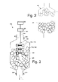
- Fig. 2 shows a schematic diagram of an example of the gasifier 40.
- the feedstock materials 20 tend to form a bridge of material 65 therein. This bridge of material 65 may prevent entry of further feedstock materials 20 such that the resultant flow of the producer gas 25 produced therein may be reduced or otherwise compromised.
- Fig. 3 shows an example of a gasifier 100 as may be described herein.
- the gasifier 100 may be used with the power generation system 15 or elsewhere.
- the gasifier 100 converts a feedstock material 110 into a producer gas 120 or other type of syngas and the like in any manner.
- the feedstock materials 110 may take the form of any type of biomass materials 130. Any other types of feedstock materials 110, however, may be used herein.
- Other component and other configurations may be used herein
- the gasifier 100 may include a reaction zone 125 positioned within an outer chamber 135.
- the gasifier 100 also may include a disruption device 140 positioned within the outer chamber 135.
- the disruption device 140 may be any type of device or system that adequately disrupts the flow of the feedstock materials 110 when entering the gasifier 100 so as to prevent the creation of the feedstock bridge 65 similar to that described above.
- the disruption device 140 may include a shaft 150 with a number of extensions 160 thereon.
- the shaft 150 may have any desired size, shape, or configuration.
- the extensions 160 may be in the form of a number of paddles 170 or any type of substantially horizontally extending structure.
- the paddles 170 or other types of the extensions 160 also may have any size, shape, or configuration. Any number of the paddles 170 or other types of the extensions 160 may be used herein in any orientation.
- the shaft 150 may be maneuvered within the outer chamber 135 by a drive device 180.
- the drive device 180 may include a conventional electrical motor and the like.
- the drive device 180 may rotate the shaft 150, shake the shaft 150, vibrate the shaft 150, or impart any type of motion to the shaft 150 and hence the extensions 160 thereon.
- the gasifier 100 also may have an insertion device 190.
- the insertion device 190 also may include an electrical motor and the like.
- the insertion device 190 may insert and remove the disruption device 140 from the gasifier 100 in any orientation. Specifically, the disruption device 140 may be inserted manually or via the insertion device 190 and/or other types of insertion means. Alternatively, the disruption device 140 may be fixed within the gasifier 100.
- Other components and other configurations may be used herein.
- the disruption device 140 may use many different components and configurations.
- Fig. 4 shows the disruption device 140 in the form of an extended spiral 200.
- the spiral 200 also may rotate, shake, vibrate, or otherwise be maneuvered therein to disrupt the creation of the bridge 80.
- Fig. 5 shows the disruption device 140 in the form of an extended screw 210.
- the extended screw 210 also may rotate, shake, vibrate, or otherwise be maneuvered therein to disrupt the creation of the bridge 80.
- Other components and other configurations may be used herein.
- the orientation of the disruption device 140 also may vary.
- Fig. 3 shows the insertion of the disruption device 140 through an upper inlet 220 of the gasifier 100 in a substantially vertical orientation 230.
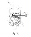
- Fig. 6 shows the insertion of the disruption device 140 via a sidewall 240 of the gasifier 100 in a substantially horizontal orientation 250. Insertion of the disruption device 140 from any direction or orientation thus may be used herein.
- Other components and other configurations also may be used herein.
- Operation of the disruption device 140 may be manually initiated or automatically initiated as part of a feedback loop.
- a pressure drop across the gasifier 100 may be determined by an input pressure sensor 260 and an output pressure sensor 270 and similar types of devices.
- An increase in the pressure drop across the gasifier 100 as determined by the sensors 260, 270 may indicate an inadequate flow of the feedstock materials 110.
- a flow sensor 280 and the like may be positioned about an exit of the gasifier 100 or elsewhere.
- a decrease in the flow of the syngas 120 also may indicate an inadequate flow of the feedstock materials 110.
- Other types of sensors may be used herein with different types of control logic. Other components and other configurations may be used herein.
- the disruption device 140 thus prevents the bridge 65 of the feedstock materials 110 from forming within the gasifier 100.
- the disruption device 140 may rotate, shake, vibrate, or otherwise maneuver to ensure an adequate flow of the feedstock materials 110.
- the disruption device 140 may take many different forms, many different orientations, and many different forms of operation.
- the gasifier 100 may provide a steady production of the producer gas 120 so as to ensure the steady operation of the overall power plant 15 and overall efficient power production. Moreover, manual operator intervention may be avoided herein.
Landscapes
- Chemical & Material Sciences (AREA)
- Engineering & Computer Science (AREA)
- Combustion & Propulsion (AREA)
- Oil, Petroleum & Natural Gas (AREA)
- Organic Chemistry (AREA)
- Processing Of Solid Wastes (AREA)
- Organic Low-Molecular-Weight Compounds And Preparation Thereof (AREA)
Applications Claiming Priority (1)
| Application Number | Priority Date | Filing Date | Title |
|---|---|---|---|
| US13/416,056 US9096807B2 (en) | 2012-03-09 | 2012-03-09 | Biomass gasifier with disruption device |
Publications (1)
| Publication Number | Publication Date |
|---|---|
| EP2636721A1 true EP2636721A1 (fr) | 2013-09-11 |
Family
ID=47844115
Family Applications (1)
| Application Number | Title | Priority Date | Filing Date |
|---|---|---|---|
| EP13157744.7A Withdrawn EP2636721A1 (fr) | 2012-03-09 | 2013-03-05 | Gazéificateur de biomasse |
Country Status (5)
| Country | Link |
|---|---|
| US (1) | US9096807B2 (fr) |
| EP (1) | EP2636721A1 (fr) |
| CN (2) | CN103305276A (fr) |
| BR (1) | BR102013004834B1 (fr) |
| CA (1) | CA2807985C (fr) |
Families Citing this family (7)
| Publication number | Priority date | Publication date | Assignee | Title |
|---|---|---|---|---|
| AU2012315914B2 (en) | 2011-09-27 | 2015-07-09 | Thermochem Recovery International, Inc. | System and method for syngas clean-up |
| US10696911B2 (en) | 2015-02-10 | 2020-06-30 | V-GRID Energy Systems | Method and system for automatic solids flow in a gasifier |
| CN105419873B (zh) * | 2015-12-31 | 2018-11-30 | 中国科学院广州能源研究所 | 防止固定床生物质气化炉架桥的方法 |
| DE102019218310A1 (de) * | 2019-11-26 | 2021-05-27 | MFC Multi Fuel Conversion GmbH | Festbettvergaser zum Erzeugen eines Produktgases aus schüttbaren kohlenstoffhaltigen Teilchen |
| US11555157B2 (en) | 2020-03-10 | 2023-01-17 | Thermochem Recovery International, Inc. | System and method for liquid fuel production from carbonaceous materials using recycled conditioned syngas |
| US11466223B2 (en) | 2020-09-04 | 2022-10-11 | Thermochem Recovery International, Inc. | Two-stage syngas production with separate char and product gas inputs into the second stage |
| SE546638C2 (en) * | 2022-10-07 | 2025-01-07 | Teknikcentrum I Gnosjoe Ab | A method and gasifier for generating synthesis gas |
Citations (6)
| Publication number | Priority date | Publication date | Assignee | Title |
|---|---|---|---|---|
| EP0101143A2 (fr) * | 1982-08-18 | 1984-02-22 | Chester D. Rogers | Conversion de biomasse en gaz combustible |
| US20050268556A1 (en) * | 2003-08-04 | 2005-12-08 | Power Reclamation, Inc. | Gasification apparatus and method |
| DE102008021966A1 (de) * | 2008-05-02 | 2009-11-12 | Hofmann, Kurt W., Dipl.-Ing. (FH) | Festbett-Vergasungsreaktor |
| WO2011057040A2 (fr) * | 2009-11-05 | 2011-05-12 | Lew Holding, Llc | Cokéfaction continue sous pression par combustion directe |
| WO2011091080A2 (fr) * | 2010-01-19 | 2011-07-28 | Zeropoint Clean Tech, Inc. | Gazéifieur à courant descendant présentant une stabilité améliorée |
| WO2012012823A1 (fr) * | 2010-07-27 | 2012-02-02 | Curtin University Of Technology | Procédé de gazéification de matière carbonée et système de gazéification |
Family Cites Families (26)
| Publication number | Priority date | Publication date | Assignee | Title |
|---|---|---|---|---|
| US4011059A (en) * | 1976-01-30 | 1977-03-08 | General Electric Company | Self-centering traversing stirrer shaft for fixed bed gasifier |
| US4134738A (en) | 1978-04-10 | 1979-01-16 | Foster Wheeler Energy Corporation | Automated poking system for coal gasifier |
| EP0045586A3 (fr) | 1980-08-02 | 1982-04-07 | Wellman Mechanical Engineering Limited | Système de ringardage pour gazogène |
| US4456455A (en) * | 1981-03-23 | 1984-06-26 | Fluidised Bed Combustion (Proprietary) Limited | Two stage coal gasification plant |
| US4453949A (en) * | 1983-03-08 | 1984-06-12 | The United States Of America As Represented By The United States Department Of Energy | Ash bed level control system for a fixed-bed coal gasifier |
| US4583992A (en) * | 1984-12-04 | 1986-04-22 | Buck Rogers Mfg. Co., Inc. | Biomass gasifier and charcoal producer |
| US4988368A (en) * | 1989-12-28 | 1991-01-29 | Shell Oil Company | Method for determination of slag tap blockage |
| CN2416383Y (zh) * | 2000-02-25 | 2001-01-24 | 朱泽玉 | 煤炭气化燃烧炉 |
| US20050155288A1 (en) * | 2003-08-04 | 2005-07-21 | Rogers Michael W. | Gasification apparatus and method |
| US7964026B2 (en) * | 2003-08-04 | 2011-06-21 | Power Reclamation, Inc. | Gasification apparatus |
| CA2626537C (fr) | 2005-10-21 | 2016-01-05 | Mark A. Paisley | Procede et systeme de gazeification associee a une extraction de goudron in-situ |
| CN2883952Y (zh) | 2005-11-17 | 2007-03-28 | 梁海兵 | 改进型生物质气化炉 |
| CN2869611Y (zh) * | 2005-12-09 | 2007-02-14 | 王晓凤 | 新型生物质燃气发生装置 |
| CA2716912C (fr) * | 2007-02-27 | 2014-06-17 | Plasco Energy Group Inc. | Systeme de gazeification avec conversion de charge d'alimentation/produit de carbonisation traite et reformulation de gaz |
| GB2453111B (en) * | 2007-09-25 | 2010-12-08 | Refgas Ltd | Gasification |
| CN101481630A (zh) * | 2009-01-22 | 2009-07-15 | 蒋启富 | 一种生物质气化炉 |
| CN201386074Y (zh) | 2009-04-29 | 2010-01-20 | 徐婷婷 | 生物质气化炉 |
| CN101701160B (zh) | 2009-10-20 | 2013-05-29 | 广州市宇联机电有限公司 | 一种多炉栅生物质气化炉 |
| CN201864700U (zh) * | 2009-10-22 | 2011-06-15 | 山东百川同创能源有限公司 | 生物质气化反应炉 |
| US8776531B2 (en) | 2009-11-06 | 2014-07-15 | General Electric Company | Gas engine drives for gasification plants |
| US20110162278A1 (en) | 2010-01-06 | 2011-07-07 | General Electric Company | System for removing fine particulates from syngas produced by gasifier |
| CN101747946B (zh) * | 2010-01-15 | 2010-12-22 | 太原理工大学 | 一种加压流化床气化炉及其操作方法 |
| CN102270003B (zh) * | 2010-06-03 | 2016-06-15 | 通用电气公司 | 控制输送固体燃料的干法进料系统的控制系统及控制方法 |
| US8888872B2 (en) | 2010-07-06 | 2014-11-18 | General Electric Company | Gasifier cooling system |
| CN101995836B (zh) * | 2010-11-01 | 2012-07-18 | 广州迪森热能技术股份有限公司 | 生物质气给料放散自动控制系统以及生物质气化反应系统 |
| US20130014440A1 (en) | 2011-07-15 | 2013-01-17 | General Electric Company | Systems, Methods, and Apparatus for Gasification |
-
2012
- 2012-03-09 US US13/416,056 patent/US9096807B2/en not_active Expired - Fee Related
-
2013
- 2013-02-28 CA CA2807985A patent/CA2807985C/fr not_active Expired - Fee Related
- 2013-02-28 BR BR102013004834-8A patent/BR102013004834B1/pt active IP Right Grant
- 2013-03-05 EP EP13157744.7A patent/EP2636721A1/fr not_active Withdrawn
- 2013-03-08 CN CN2013100737441A patent/CN103305276A/zh active Pending
- 2013-03-08 CN CN201810621285.9A patent/CN108865275A/zh active Pending
Patent Citations (6)
| Publication number | Priority date | Publication date | Assignee | Title |
|---|---|---|---|---|
| EP0101143A2 (fr) * | 1982-08-18 | 1984-02-22 | Chester D. Rogers | Conversion de biomasse en gaz combustible |
| US20050268556A1 (en) * | 2003-08-04 | 2005-12-08 | Power Reclamation, Inc. | Gasification apparatus and method |
| DE102008021966A1 (de) * | 2008-05-02 | 2009-11-12 | Hofmann, Kurt W., Dipl.-Ing. (FH) | Festbett-Vergasungsreaktor |
| WO2011057040A2 (fr) * | 2009-11-05 | 2011-05-12 | Lew Holding, Llc | Cokéfaction continue sous pression par combustion directe |
| WO2011091080A2 (fr) * | 2010-01-19 | 2011-07-28 | Zeropoint Clean Tech, Inc. | Gazéifieur à courant descendant présentant une stabilité améliorée |
| WO2012012823A1 (fr) * | 2010-07-27 | 2012-02-02 | Curtin University Of Technology | Procédé de gazéification de matière carbonée et système de gazéification |
Also Published As
| Publication number | Publication date |
|---|---|
| CA2807985A1 (fr) | 2013-09-09 |
| CA2807985C (fr) | 2020-03-24 |
| US20130232873A1 (en) | 2013-09-12 |
| BR102013004834B1 (pt) | 2020-10-06 |
| CN108865275A (zh) | 2018-11-23 |
| BR102013004834A2 (pt) | 2015-07-21 |
| CN103305276A (zh) | 2013-09-18 |
| US9096807B2 (en) | 2015-08-04 |
Similar Documents
| Publication | Publication Date | Title |
|---|---|---|
| EP2636721A1 (fr) | Gazéificateur de biomasse | |
| CN107995921A (zh) | 气化系统 | |
| US20110162278A1 (en) | System for removing fine particulates from syngas produced by gasifier | |
| US20130142723A1 (en) | Biomass gasification systems having controllable fluid injectors | |
| Sharma et al. | Small-scale toroidal fluidized bed gasification system: development and experimental aspects | |
| CN102190394A (zh) | 采用喷射器的气化系统 | |
| US10851319B2 (en) | Gasification system and method | |
| CN102776032B (zh) | 用于冷却气化产物的系统和方法 | |
| WO2021091812A1 (fr) | Tube de brûleur | |
| CN103977891B (zh) | 用于煤精选的系统和方法 | |
| CA2726406C (fr) | Procede et appareil pour le transport de matieres solides | |
| US20120311991A1 (en) | Biofilter assemblies for biomass gasification systems | |
| CN104232163A (zh) | 气化系统及方法 | |
| CN102918328B (zh) | 用于给料喷射的系统和方法 | |
| KR101997506B1 (ko) | 싸이클론 가스화기 | |
| US20140223821A1 (en) | Pressurized Gasification Process | |
| CA2912123A1 (fr) | Procede et installation de gazeification au moins partielle d'un materiau d'alimentation organique solide | |
| EP2399973A1 (fr) | Système de gazéification de biomasse et procédé de gazéification de biomasse | |
| CN110291178B (zh) | 气化装置 | |
| US20120273176A1 (en) | Systems and methods for cooling gasification products | |
| EP3505602A1 (fr) | Systéme de gasification | |
| WO2013068052A1 (fr) | Procédé et système pour la production d'un gaz pauvre de gazogène | |
| JP7449325B2 (ja) | 燃料製造システム | |
| US9011559B2 (en) | Scrubber assembly with guide vanes | |
| Ab Rahman et al. | Air gasification of palm biomass for producing tar-free higher heating value producer gas |
Legal Events
| Date | Code | Title | Description |
|---|---|---|---|
| PUAI | Public reference made under article 153(3) epc to a published international application that has entered the european phase |
Free format text: ORIGINAL CODE: 0009012 |
|
| AK | Designated contracting states |
Kind code of ref document: A1 Designated state(s): AL AT BE BG CH CY CZ DE DK EE ES FI FR GB GR HR HU IE IS IT LI LT LU LV MC MK MT NL NO PL PT RO RS SE SI SK SM TR |
|
| AX | Request for extension of the european patent |
Extension state: BA ME |
|
| 17P | Request for examination filed |
Effective date: 20140311 |
|
| RBV | Designated contracting states (corrected) |
Designated state(s): AL AT BE BG CH CY CZ DE DK EE ES FI FR GB GR HR HU IE IS IT LI LT LU LV MC MK MT NL NO PL PT RO RS SE SI SK SM TR |
|
| 17Q | First examination report despatched |
Effective date: 20150127 |
|
| STAA | Information on the status of an ep patent application or granted ep patent |
Free format text: STATUS: THE APPLICATION IS DEEMED TO BE WITHDRAWN |
|
| 18D | Application deemed to be withdrawn |
Effective date: 20170509 |