EP2636798A1 - Plattengleitvorrichtung - Google Patents
Plattengleitvorrichtung Download PDFInfo
- Publication number
- EP2636798A1 EP2636798A1 EP13000812.1A EP13000812A EP2636798A1 EP 2636798 A1 EP2636798 A1 EP 2636798A1 EP 13000812 A EP13000812 A EP 13000812A EP 2636798 A1 EP2636798 A1 EP 2636798A1
- Authority
- EP
- European Patent Office
- Prior art keywords
- base plate
- plate
- sliding device
- molded part
- underside
- Prior art date
- Legal status (The legal status is an assumption and is not a legal conclusion. Google has not performed a legal analysis and makes no representation as to the accuracy of the status listed.)
- Granted
Links
Images


Classifications
-
- E—FIXED CONSTRUCTIONS
- E02—HYDRAULIC ENGINEERING; FOUNDATIONS; SOIL SHIFTING
- E02D—FOUNDATIONS; EXCAVATIONS; EMBANKMENTS; UNDERGROUND OR UNDERWATER STRUCTURES
- E02D3/00—Improving or preserving soil or rock, e.g. preserving permafrost soil
- E02D3/02—Improving by compacting
- E02D3/046—Improving by compacting by tamping or vibrating, e.g. with auxiliary watering of the soil
Definitions
- the present invention relates to a plate sliding device for a base plate of a compacting device for working a bottom portion, having a first surface, with which the plate sliding device rests on the bottom portion for machining, and a second surface, with which the plate sliding device contacts an underside of the base plate, when the plate slide is fixed to the base plate. Furthermore, the present invention relates to a compacting device for processing a bottom section with a base plate comprising such a plate sliding device.
- the respective ground sections will sink over time, which leads to damage to the floor coverings applied to the floor sections.
- floor coverings may be asphalt pavements of roads or paving of sidewalks or terraces.
- the setting of the floor sections can be reduced to a level by compacting the soil so that the floor coverings do not suffer any significant damage.
- the aforementioned compression devices are used, which are also called vibrating or vibrating plates and having a base plate which is moved by a drive unit using imbalances. These movements cause a compression of the processed with the compaction devices bottom sections.
- the floor section can be compacted both before and after application of the floor covering.
- a molding is used, which is applied to the underside of the base plate and thus both the paving stones and the underside of the base plate from damage due to the Vibratory movements can occur, protects.
- plate sliders also improve the sliding properties of the compacting device on the floor covering.
- the plate slide is formed as a plastic plate of uniform thickness, which is screwed to the base plate.
- the base plates have a substantially rectangular outline, wherein they are rounded to their perpendicular to the machining direction edges out there and do not come into direct contact with the bottom portion.
- the bottom section may have unevenness and obstacles such as protruding stones. Without the rounding, the base plate would hit directly against the obstacles, which would complicate the processing of the bottom section.
- the object of the present invention is therefore to provide a plate slide of the type mentioned, with which the disadvantages of the prior art can be counteracted and which makes it possible to increase the effective area of the base plate and relative movements between the base plate and the plate slide and the resulting to reduce resulting power losses.
- the object is achieved with a molding in which the underside of the base plate and the second surface of the molding have a mutually corresponding profile, so that the molding is fastened to the base plate substantially void-free.
- a corresponding course should be understood to mean that the base plate and the molded part are constructed like positive and negative molds that fit one another, and the underside of the base plate and the second surface of the molded part extend in such a way that they are substantially closed and form an uninterrupted contact surface.
- the use of the term "essentially” is intended to express that, depending on the manufacturing and fastening method used and within the scope of manufacturing accuracy small cavities may arise.
- the object according to the invention is to approximate the progressions of the underside and the second surface so that as far as possible no cavities are formed.
- the compacting device can be operated more efficiently and cost-effectively. Since in many cases the compression devices are driven by internal combustion engines, a contribution is also made to reducing fuel consumption and emissions.
- the first surface of the molded part forms a substantially planar plane.
- the first surface which comes into contact with the bottom portion to be processed, does not follow the rounding of the base plate in this embodiment, and thus rests completely on the bottom portion to be processed.
- the molded part fills the existing in the region of the rounding between the first and the second surface volume. The contact area to the bottom portion is increased and consequently the compacting device is used more effectively.
- the first surface preferably has a surface area which corresponds to an area of a surface projected onto a plane of the underside of the base plate.
- the entire projected area of the underside of the base plate can thus be used for processing the bottom portion, including the areas of the rounding, which is not the case with known Plattengleitvorraumen.
- the contact area with the bottom section is increased and, on the other hand, areas of floor sections adjacent to obstacles such as walls can be processed and therefore not accessible due to the rounding with known compacting devices.
- the first surface has a surface area greater than an area of a plane projected surface of the underside of the base plate.
- the contact surface is further increased to the bottom portion, so that the compression device can act on an even larger area of the bottom portion to be processed.
- the processing time is reduced for a given floor section, so that the inventive Compressor can be operated more effectively compared to known compression devices.
- the shaped part protrudes beyond the base plate in the machining direction and has an end face extending essentially perpendicular to the first surface, which adjoins the first surface.
- the contact surface to be processed to the bottom portion of this contribution to the safety of the operator of the compacting device is made.
- the molding is positively or materially secured to the underside of the base plate.
- a firm and permanent connection between the base plate and the molded part can be created, which is particularly suitable for permanently transferring high forces to the molded part.
- the risk that the molded part uncontrollably detached from the base plate is significantly minimized.
- a dovetail connection may be provided, in which the molded part is connected to the base plate by a movement directed perpendicular to the machining direction.
- the molding is releasably connected to the base plate and can be replaced if necessary, for example, in advanced wear or when working on another floor covering.
- the molding is made of plastic and vulcanized to the base plate, molded or molded.
- the plastic can be chosen so that it is adapted to the flooring to be processed and in particular to the paving stones used, so that they are optimally protected.
- the attachment or manufacturing process of the molding so the scorching, the molding or casting, the ability to inexpensively attach the molding cavity-free to the base plate.
- the molding according to the invention is made of metal and cast on the base plate.
- This training is particularly suitable for hard-to-machine soil sections, in which damage during processing play no significant role, for example, cobblestones for roads.
- the metal used is aluminum. Due to the low weight of aluminum compared to other metals, the operability of the compacting device is limited to only a small extent, moreover, the fuel consumption for operating the compacting device is only slightly increased.
- the molding is made of plastic, wood or metal and releasably attachable to the base plate.
- the molded part can be easily exchanged depending on the nature of the floor section to be processed, thus achieving an ideal match between the molded part and the floor section.
- brackets or screws can be used.
- a molded wood which is inexpensive to manufacture, so that you take a certain amount of wear into account. If the wear exceeds a certain level, the molded part can be easily replaced with a new molded part.
- a further aspect of the present invention relates to a compacting device for processing a bottom section with a base plate and a molded part according to one of the previously discussed embodiments.
- the technical effects and advantages that have been mentioned for the molded part according to the invention apply equally to the compacting device.
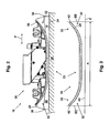
- FIG. 1 shows a compression device 10 according to the invention according to an embodiment with reference to a side view.
- the compacting device 10 comprises a housing 12 in which a drive unit 14 is housed, which generates vibrating and vibrating movements in a known manner and transmits these movements to a base plate 16.
- a molding 18 according to the invention is attached, which comes into contact with a bottom portion 20 to be processed.
- the user grasps the compacting device 10 at an operating section 22 and, by operating a lever 24, can carry out the desired processing steps and compact the bottom section 20.
- the compression device 10 can be moved along a machining direction, which is indicated by the arrow P.
- FIG. 2 the base plate 16 and the molded part 18 are shown detached from the rest of the compression device 10.
- the base plate 16 has connections 26, with which it can be connected to the drive unit 14 of the compression device 10 and via which the movements generated by the drive unit 14 are transmitted to the base plate 16.
- the base plate 16 on an underside 28, which has a planar portion 30 and two rounded portions 32, the geometric axis of rotation extends perpendicular to the machining direction, so that increases in the region of the rounded portions 32 of the distance of the base plate 16 to the bottom portion 20.
- the molding 18 has a first surface 34, which forms a substantially planar plane and rests on the bottom portion 20 during machining. Furthermore, the molded part 18 has a second surface 36, with which the molded part 18 rests against the underside 28 of the base plate 16 when the molded part 18 is attached to the base plate 16. In this case, the underside 28 and the second surface 36 on a mutually corresponding course, so that no gap or no cavity between the bottom 28 and the second surface 36 and the contact between the bottom 28 and the second surface 36 is not interrupted. With others In words, the molded part 18 is a negative mold to the base plate 16, so that the base plate 16 and the second surface 36 over the entire surface abut each other.
- the molded part 18 has an end face 38 extending perpendicular to the first surface 34.
- two end faces 38 are provided, each of which adjoins the first surface 34 in the machining direction.
- the illustrated molded part 18 comprises two further end faces 38 which adjoin the first surface 34 perpendicular to the machining direction (see also FIG FIG. 4 ).
- the shaped part 18 protrudes beyond the base plate 16 in the illustrated embodiment, so that the surface area of the first surface 34 is greater than the area of a surface E projected onto a plane E of the underside 28 of the base plate 16.
- the projected area is 40 the bottom 28 in FIG. 3 defined in more detail.
- the base plate 16 is in FIG. 3 shown by a basic sectional view without the terminals 26.
- the projected area 40 is delimited by boundary planes BE which are perpendicular to the plane and bear against outer edges 42 of the base plate 16.
- the projected area 40 of the underside 28 has the extent A in the illustrated plane.
- the shaped part 18 can of course also project perpendicular to the machining direction over the base plate 16.
- FIG. 4 the molding 18 according to the invention is shown separately by means of a perspective view.
- One recognizes the second surface 36 as well as the end faces 38 of the molding 18.
- the molding 18 has a substantially rectangular shape, so that a total of four end faces 38 are present, of which only two end faces 38 in FIG. 4 are visible.
Landscapes
- Engineering & Computer Science (AREA)
- Life Sciences & Earth Sciences (AREA)
- Structural Engineering (AREA)
- Agronomy & Crop Science (AREA)
- Environmental & Geological Engineering (AREA)
- Soil Sciences (AREA)
- General Life Sciences & Earth Sciences (AREA)
- Mining & Mineral Resources (AREA)
- Paleontology (AREA)
- Civil Engineering (AREA)
- General Engineering & Computer Science (AREA)
- Road Paving Machines (AREA)
Abstract
Description
- Die vorliegende Erfindung betrifft eine Plattengleitvorrichtung für eine Grundplatte einer Verdichtungsvorrichtung zum Bearbeiten eines Bodenabschnitts, mit einer ersten Oberfläche, mit welcher die Plattengleitvorrichtung zum Bearbeiten auf dem Bodenabschnitt aufliegt, und einer zweiten Oberfläche, mit welcher die Plattengleitvorrichtung mit einer Unterseite der Grundplatte in Kontakt tritt, wenn die Plattengleitvorrichtung an der Grundplatte befestigt ist. Ferner betrifft die vorliegende Erfindung eine Verdichtungsvorrichtung zum Bearbeiten eines Bodenabschnitts mit einer Grundplatte umfassend eine derartige Plattengleitvorrichtung.
- Werden bei Bodenarbeiten Aufschüttungen oder sonstige Erdbewegungen vorgenommen, besteht die Gefahr, dass sich die betreffenden Bodenabschnitte im Laufe der Zeit senken, was zu Schäden an den auf die Bodenabschnitte aufgebrachten Bodenbelägen führt. Beispiele für derartige Bodenbeläge können Asphaltbeläge von Straßen oder Pflasterbeläge von Bürgersteigen oder Terrassen sein. Das Setzen der Bodenabschnitte kann durch eine Verdichtung des Erdreichs auf ein Maß reduziert werden, so dass die Bodenbeläge keinen nennenswerten Schaden erleiden. Hierzu werden die eingangs genannten Verdichtungsvorrichtungen verwendet, die auch Rüttel- oder Vibrationsplatten genannt werden und eine Grundplatte aufweisen, die von einer Antriebseinheit unter Verwendung von Unwuchten bewegt wird. Diese Bewegungen bewirken eine Verdichtung der mit den Verdichtungsvorrichtungen bearbeiteten Bodenabschnitte.
- Bei der Bearbeitung kann der Bodenabschnitt sowohl vor als auch nach Aufbringen des Bodenbelags verdichtet werden. Ist beispielsweise eine Pflasterung als Bodenbelag vorgesehen, so besteht die Gefahr, dass die Pflastersteine bei der Verdichtung beschädigt werden. Um dies zu verhindern, wird ein Formteil verwendet, welches auf die Unterseite der Grundplatte aufgebracht wird und somit sowohl die Pflastersteine als auch die Unterseite der Grundplatte vor Schäden, die infolge der Vibrationsbewegungen auftreten können, schützt. Neben dem schützenden Aspekt verbessern derartige Plattengleitvorrichtungen auch die Gleiteigenschaften der Verdichtungsvorrichtung auf dem Bodenbelag. Bei bekannten Verdichtungsvorrichtungen ist die Plattengleitvorrichtung als Kunststoffplatte gleichmäßiger Dicke ausgebildet, die an die Grundplatte angeschraubt wird.
- Üblicherweise weisen die Grundplatten einen im Wesentlichen rechteckigen Umriss auf, wobei sie zu ihren senkrecht zur Bearbeitungsrichtung liegenden Kanten hin abgerundet sind und dort nicht in unmittelbaren Kontakt mit dem Bodenabschnitt treten. Insbesondere dann, wenn der Bodenabschnitt direkt, also ohne Bodenbelag verdichtet werden soll, kann der Bodenabschnitt Unebenheiten und Hindernisse wie hervorstehende Steine aufweisen. Ohne die Abrundungen würde die Grundplatte direkt gegen die Hindernisse stoßen, was die Bearbeitung des Bodenabschnitts erschweren würde. Werden derartige Verdichtungsvorrichtungen jedoch zum Verdichten eines Bodenabschnitts verwendet, der bereits einen Belag aufweist, sind die Unebenheiten des Bodenabschnitts deutlich minimiert, so dass in diesem Fall der Nachteil auftritt, dass die Grundplatte im Bereich der Abrundung nicht zur Verdichtung des Bodenabschnitts beiträgt, da dort kein Kontakt zwischen der Grundplatte und dem Bodenabschnitt besteht. Zudem liegen die aus dem Stand der Technik bekannten Plattengleitvorrichtungen im Bereich der Abrundungen nicht vollständig an der Grundplatte an, so dass ein Spalt oder ein Hohlraum zwischen der Plattengleitvorrichtung und der Grundplatte entsteht. Hierdurch kommt es zu Relativbewegungen zwischen der Plattengleitvorrichtung und der Grundplatte, was sich negativ auf das Laufverhalten der Verdichtungsvorrichtung auswirkt und zu Leistungsverlusten führt.
- Aufgabe der vorliegenden Erfindung ist es daher, eine Plattengleitvorrichtung der eingangs genannten Art anzugeben, mit welcher den Nachteilen des Stands der Technik begegnet werden kann und welche es ermöglicht, die wirksame Fläche der Grundplatte zu vergrößern und Relativbewegungen zwischen der Grundplatte und der Plattengleitvorrichtung und die hieraus resultierenden Leistungsverluste zu verringern.
- Gelöst wird die Aufgabe mit einem Formteil, bei welchem die Unterseite der Grundplatte und die zweite Oberfläche des Formteils einen zueinander korrespondierenden Verlauf aufweisen, so dass das Formteil im Wesentlichen hohlraumfrei an der Grundplatte befestigbar ist. Unter einem korrespondierenden Verlauf soll hier verstanden werden, dass die Grundplatte und das Formteil wie zueinander passende Positiv- und Negativformen aufgebaut sind und die Unterseite der Grundplatte und die zweite Oberfläche des Formteils so verlaufen, dass sie eine im Wesentlichen geschlossene und unterbrechungsfreie Kontaktfläche bilden. Die Verwendung des Begriffs "im Wesentlichen" soll dabei zum Ausdruck bringen, dass je nach verwendetem Fertigungs- und Befestigungsverfahren und im Rahmen der Fertigungsgenauigkeit kleine Hohlräume entstehen können. Das erfindungsgemäße Ziel ist jedoch, die Verläufe der Unterseite und der zweiten Oberfläche so einander anzunähern, dass möglichst keine Hohlräume entstehen. Auf diese Weise werden Relativbewegungen zwischen dem Formteil und der Grundplatte minimiert, so dass das Laufverhalten der Verdichtungsvorrichtung verbessert und Leistungsverluste verringert werden. Mit Hilfe des erfindungsgemäßen Formteils kann die Verdichtungsvorrichtung effizienter und kostengünstiger betrieben werden. Da in vielen Fällen die Verdichtungsvorrichtungen mit Verbrennungsmotoren angetrieben werden, wird auch ein Beitrag zur Senkung des Treibstoffverbrauchs und der Emissionen geleistet.
- In einer Weiterbildung der vorliegenden Erfindung bildet die erste Oberfläche des Formteils eine im Wesentlichen planare Ebene. Die erste Oberfläche, die mit dem zu bearbeitenden Bodenabschnitt in Kontakt kommt, folgt in dieser Ausgestaltung den Abrundungen der Grundplatte nicht und liegt somit vollständig auf dem zu bearbeitenden Bodenabschnitt auf. Das Formteil füllt das im Bereich der Abrundungen zwischen der ersten und der zweiten Oberfläche vorhandene Volumen auf. Die Kontaktfläche zum Bodenabschnitt wird vergrößert und folglich die Verdichtungsvorrichtung effektiver genutzt.
- Vorzugsweise weist dabei die erste Oberfläche einen Flächeninhalt auf, der einem Flächeninhalt einer auf eine Ebene projizierten Fläche der Unterseite der Grundplatte entspricht. Die gesamte projizierte Fläche der Unterseite der Grundplatte kann folglich zum Bearbeiten des Bodenabschnitts verwendet werden, also auch die Bereiche der Abrundungen, was bei bekannten Plattengleitvorrichtungen nicht der Fall ist. Zum einen wird die Kontaktfläche zum Bodenabschnitt vergrößert und zum anderen können Bereiche von Bodenabschnitten bearbeitet werden, die sich benachbart zu Hindernissen wie Wänden befinden und daher aufgrund der Abrundung mit bekannten Verdichtungsvorrichtungen nicht zugänglich sind.
- Idealerweise weist die erste Oberfläche einen Flächeninhalt auf, der größer ist als ein Flächeninhalt einer auf eine Ebene projizierten Fläche der Unterseite der Grundplatte. Somit wird die Kontaktfläche zum Bodenabschnitt noch weiter vergrößert, so dass die Verdichtungsvorrichtung auf einen noch größeren Bereich des zu bearbeitenden Bodenabschnitts einwirken kann. Hierdurch wird die Bearbeitungszeit für einen gegebenen Bodenabschnitt verringert, so dass die erfindungsgemäße Verdichtungsvorrichtung effektiver im Vergleich zu bekannten Verdichtungsvorrichtungen betrieben werden kann.
- Vorzugsweise ragt das Formteil in Bearbeitungsrichtung über die Grundplatte hervor und weist eine im Wesentlichen senkrecht zur ersten Oberfläche verlaufende Stirnfläche auf, die sich der ersten Oberfläche anschließt. Neben der bereits zuvor erwähnten Vergrößerung der Kontaktfläche zum zu bearbeitenden Bodenabschnitt wird hierdurch ein Beitrag zur Sicherheit des Bedieners der Verdichtungsvorrichtung geleistet. Sollte er bei sich in Bearbeitungsrichtung bewegender Verdichtungsvorrichtung seinen Fuß aus welchen Gründen auch immer im Bereich der Grundplatte belassen haben, so stößt er gegen die Stirnfläche an, was ein deutliches Zeichen für ihn ist, den Fuß zu entfernen. Dabei besteht nicht die Gefahr, dass sein Fuß in den Bereich der Abrundungen gelangt und eingequetscht wird, wie es bei aus dem Stand der Technik bekannten Verdichtungsvorrichtungen möglich ist. Die Sicherheit im Betrieb der erfindungsgemäßen Verdichtungsvorrichtung wird somit erhöht.
- Vorzugsweise ist das Formteil form- oder stoffschlüssig an der Unterseite der Grundplatte befestigt. Im Fall eines Stoffschlusses kann eine feste und unlösbare Verbindung zwischen der Grundplatte und dem Formteil geschaffen werden, die sich insbesondere dazu eignet, hohe Kräfte dauerhaft auf das Formteil zu übertragen. Die Gefahr, dass sich das Formteil unkontrolliert von der Grundplatte löst, wird deutlich minimiert. Zur Realisierung eines Formschlusses kann beispielsweise eine Schwalbenschwanzverbindung vorgesehen sein, bei welcher das Formteil durch eine senkrecht zur Bearbeitungsrichtung gerichtete Bewegung mit der Grundplatte verbunden wird. In dieser Ausführung ist das Formteil lösbar mit der Grundplatte verbunden und kann bei Bedarf ausgetauscht werden, beispielsweise bei fortgeschrittenem Verschleiß oder bei Bearbeitung eines anderen Bodenbelags.
- In einer vorteilhaften Weiterbildung ist das Formteil aus Kunststoff gefertigt und an die Grundplatte anvulkanisiert, angespritzt oder angegossen. Der Kunststoff kann so gewählt werden, dass er auf den zu bearbeitenden Bodenbelag und insbesondere auf die verwendeten Pflastersteine angepasst ist, so dass diese optimal geschützt sind. Darüber hinaus bieten die Befestigungs- bzw. Fertigungsverfahren des Formteils, also das Anvulkanisieren, das Anspritzen oder das Angießen, die Möglichkeit, auf kostengünstige Weise das Formteil hohlraumfrei an die Grundplatte anzubringen.
- In einer Fortbildung ist das erfindungsgemäße Formteil aus Metall gefertigt und an der Grundplatte angegossen. Diese Fortbildung eignet sich besonders für schwer zu bearbeitende Bodenabschnitte, bei denen Beschädigungen bei der Bearbeitung keine nennenswerte Rolle spielen, beispielsweise bei Kopfsteinpflaster für Straßen.
- Vorzugsweise wird als Metall Aluminium verwendet. Aufgrund des im Vergleich zu anderen Metallen geringen Gewichts von Aluminium wird die Bedienbarkeit der Verdichtungsvorrichtung in nur geringem Umfang eingeschränkt, zudem wird der Treibstoffverbrauch zum Betreiben der Verdichtungsvorrichtung nur unwesentlich erhöht.
- In einer weiteren Ausgestaltung ist das Formteil aus Kunststoff, Holz oder Metall gefertigt und an der Grundplatte lösbar befestigbar. In dieser Ausführungsform kann das Formteil je nach Beschaffenheit des zu bearbeitenden Bodenabschnitts einfach ausgetauscht und so eine ideale Abstimmung zwischen Formteil und Bodenabschnitt erreicht werden. Hierzu können beispielsweise Klammern oder Schrauben verwendet werden. Bei besonders empfindlichen Pflastersteinen bietet sich die Verwendung eines Formteils aus Holz an, welches kostengünstig zu fertigen ist, so dass man einen gewissen Verschleiß in Kauf nimmt. Überschreitet der Verschleiß ein bestimmtes Maß, kann das Formteil auf einfache Weise gegen ein neues Formteil ersetzt werden. Zudem ist es in dieser Ausführungsform problemlos möglich, bestehende Verdichtungsvorrichtungen mit dem erfindungsgemäßen Formteil nachzurüsten. Die Flexibilität in der Verwendung des erfindungsgemäßen Formteils wird in dieser Ausgestaltung erhöht.
- Ein weiterer Aspekt der vorliegenden Erfindung betrifft eine Verdichtungsvorrichtung zum Bearbeiten eines Bodenabschnitts mit einer Grundplatte und einem Formteil nach einem der zuvor diskutierten Ausführungsbeispiele. Die technischen Effekte und Vorteile, die für das erfindungsgemäße Formteil genannt wurden, gelten gleichermaßen für die Verdichtungsvorrichtung.
- Die vorliegende Erfindung wird unter Bezugnahme auf die anhängenden Zeichnungen anhand eines bevorzugten Ausführungsbeispiels im Detail erläutert. Es zeigen
- Fig. 1
- eine Seitenansicht eines ersten Ausführungsbeispiels einer erfindungsgemäßen Verdichtungsvorrichtung,
- Fig. 2
- eine Seitenansicht auf eine Grundplatte und ein erfindungsgemäßes Formteil,
- Fig. 3
- eine Prinzipskizze zur Veranschaulichung der projizierten Fläche der Grundplatte, und
- Fig. 4
- eine perspektivische Ansicht auf das erfindungsgemäße Formteil.
-
Figur 1 zeigt eine erfindungsgemäße Verdichtungsvorrichtung 10 gemäß einem Ausführungsbeispiel anhand einer Seitenansicht. Die Verdichtungsvorrichtung 10 umfasst ein Gehäuse 12, in welchem eine Antriebseinheit 14 untergebracht ist, die Rüttel- und Vibrationsbewegungen auf bekannte Weise erzeugt und diese Bewegungen auf eine Grundplatte 16 überträgt. - An der Grundplatte 16 ist ein erfindungsgemäßes Formteil 18 befestigt, welches in Kontakt mit einem zu bearbeitenden Bodenabschnitt 20 tritt. Zum Bearbeiten des Bodenabschnitts 20 ergreift der Benutzer die Verdichtungsvorrichtung 10 an einem Bedienungsabschnitt 22 und kann durch Betätigen eines Hebels 24 die gewünschten Bearbeitungsschritte ausführen und den Bodenabschnitt 20 verdichten. Dabei kann die Verdichtungsvorrichtung 10 entlang einer Bearbeitungsrichtung bewegt werden, die mit dem Pfeil P angedeutet ist.
- In
Figur 2 sind die Grundplatte 16 und das Formteil 18 losgelöst von der übrigen Verdichtungsvorrichtung 10 dargestellt. Die Grundplatte 16 weist Anschlüsse 26 auf, mit denen sie an die Antriebseinheit 14 der Verdichtungsvorrichtung 10 angeschlossen werden kann und über welche die von der Antriebseinheit 14 erzeugten Bewegungen auf die Grundplatte 16 übertragen werden. Weiterhin weist die Grundplatte 16 eine Unterseite 28 auf, welche einen planaren Abschnitt 30 und zwei Abrundungen 32 aufweist, deren geometrische Drehachse sich senkrecht zur Bearbeitungsrichtung erstreckt, so dass sich im Bereich der Abrundungen 32 der Abstand der Grundplatte 16 zum Bodenabschnitt 20 vergrößert. - Das Formteil 18 weist eine erste Oberfläche 34 auf, die eine im Wesentlichen planare Ebene bildet und beim Bearbeiten auf dem Bodenabschnitt 20 aufliegt. Ferner weist das Formteil 18 eine zweite Oberfläche 36 auf, mit der das Formteil 18 an der Unterseite 28 der Grundplatte 16 anliegt, wenn das Formteil 18 an der Grundplatte 16 befestigt ist. Dabei weisen die Unterseite 28 und die zweite Oberfläche 36 einen zueinander korrespondierenden Verlauf auf, so dass zwischen der Unterseite 28 und der zweiten Oberfläche 36 kein Spalt oder kein Hohlraum entsteht und der Kontakt zwischen der Unterseite 28 und der zweiten Oberfläche 36 nicht unterbrochen wird. Mit anderen Worten stellt das Formteil 18 eine Negativform zur Grundplatte 16 dar, so dass die Grundplatte 16 und die zweite Oberfläche 36 vollflächig aneinander anliegen.
- Weiterhin weist das Formteil 18 eine senkrecht zur ersten Oberfläche 34 verlaufende Stirnfläche 38 auf. In diesem Fall sind zwei Stirnflächen 38 vorgesehen, die sich jeweils in Bearbeitungsrichtung an die erste Oberfläche 34 anschließen. Darüber hinaus umfasst das dargestellte Formteil 18 zwei weitere Stirnflächen 38, die sich senkrecht zur Bearbeitungsrichtung an die erste Oberfläche 34 anschließen (vgl. auch
Figur 4 ). - In Bearbeitungsrichtung steht das Formteil 18 im dargestellten Ausführungsbeispiel über die Grundplatte 16 hervor, so dass der Flächeninhalt der ersten Oberfläche 34 größer ist als der Flächeninhalt einer auf eine Ebene E projizierten Fläche 40 der Unterseite 28 der Grundplatte 16. Zur Veranschaulichung ist die projizierte Fläche 40 der Unterseite 28 in
Figur 3 näher definiert. Die Grundplatte 16 ist inFigur 3 anhand einer prinzipiellen Schnittdarstellung ohne die Anschlüsse 26 gezeigt. Die projizierte Fläche 40 wird von senkrecht auf der Ebene stehenden Begrenzungsebenen BE begrenzt, die an äußeren Kanten 42 der Grundplatte 16 anliegen. Die projizierte Fläche 40 der Unterseite 28 hat in der dargestellten Ebene die Erstreckung A. Das Formteil 18 kann selbstverständlich auch senkrecht zur Bearbeitungsrichtung über die Grundplatte 16 hervorstehen. - In
Figur 4 ist das erfindungsgemäße Formteil 18 anhand einer perspektivischen Darstellung separat gezeigt. Man erkennt die zweite Oberfläche 36 sowie die Stirnflächen 38 des Formteils 18. Das Formteil 18 weist eine im Wesentlichen rechteckige Form auf, so dass insgesamt vier Stirnflächen 38 vorhanden sind, von denen nur zwei Stirnflächen 38 inFigur 4 sichtbar sind.
Claims (10)
- Plattengleitvorrichtung für eine Grundplatte (16) einer Verdichtungsvorrichtung (10) zum Bearbeiten eines Bodenabschnitts (20), mit- einer ersten Oberfläche (34), mit welcher die Plattengleitvorrichtung (18) zum Bearbeiten auf dem Bodenabschnitt (20) aufliegt, und- einer zweiten Oberfläche (36), mit welcher die Plattengleitvorrichtung (18) mit einer Unterseite (28) der Grundplatte (16) in Kontakt tritt, wenn die Plattengleitvorrichtung (18) an der Grundplatte (16) befestigt ist,
dadurch gekennzeichnet,
dass die Plattengleitvorrichtung als Formteil (18) ausgebildet ist, wobei die Unterseite (28) und die zweite Oberfläche (36) einen zueinander korrespondierenden Verlauf aufweisen, so dass das Formteil (18) im Wesentlichen hohlraumfrei an der Grundplatte (16) befestigbar ist, und dass die erste Oberfläche (34) eine im Wesentlichen planare Ebene bildet. - Plattengleitvorrichtung nach Anspruch 1,
dadurch gekennzeichnet,
dass die erste Oberfläche (34) einen Flächeninhalt aufweist, der einem Flächeninhalt einer auf eine Ebene (E) projizierten Fläche (40) der Unterseite (28) der Grundplatte (16) entspricht. - Plattengleitvorrichtung nach Anspruch 1,
dadurch gekennzeichnet,
dass die erste Oberfläche (34) einen Flächeninhalt aufweist, der größer ist als ein Flächeninhalt einer auf eine Ebene (E) projizierten Fläche (40) der Unterseite (28) der Grundplatte (16). - Plattengleitvorrichtung nach Anspruch 3,
dadurch gekennzeichnet,
dass das Formteil (18) in Bearbeitungsrichtung über die Grundplatte (16) hervorragt und eine im Wesentlichen senkrecht zur ersten Oberfläche (34) verlaufende Stirnfläche (38) aufweist, die sich der ersten Oberfläche (34) anschließt. - Plattengleitvorrichtung nach einem der vorherigen Ansprüche,
dadurch gekennzeichnet,
dass das Formteil (18) form- oder stoffschlüssig an der Unterseite (28) der Grundplatte (16) befestigt ist. - Plattengleitvorrichtung nach Anspruch 5,
dadurch gekennzeichnet,
dass das Formteil (18) aus Kunststoff gefertigt und an die Grundplatte (16) anvulkanisiert, angespritzt oder angegossen ist. - Plattengleitvorrichtung nach einem der vorherigen Ansprüche 1 bis 5,
dadurch gekennzeichnet,
dass das Formteil (18) aus Metall gefertigt und an der Grundplatte (16) angegossen ist. - Plattengleitvorrichtung nach Anspruch 7,
dadurch gekennzeichnet,
dass als Metall Aluminium verwendet wird. - Plattengleitvorrichtung nach einem der vorherigen Ansprüche 1 bis 4,
dadurch gekennzeichnet,
dass das Formteil (18) aus Kunststoff, Holz oder Metall gefertigt und an der Grundplatte (16) lösbar befestigbar ist. - Verdichtungsvorrichtung zum Bearbeiten eines Bodenabschnitts mit einer Grundplatte (16), gekennzeichnet durch ein Formteil (18) nach einem der vorherigen Ansprüche.
Applications Claiming Priority (1)
| Application Number | Priority Date | Filing Date | Title |
|---|---|---|---|
| DE201210004436 DE102012004436A1 (de) | 2012-03-05 | 2012-03-05 | Plattengleitvorrichtung |
Publications (2)
| Publication Number | Publication Date |
|---|---|
| EP2636798A1 true EP2636798A1 (de) | 2013-09-11 |
| EP2636798B1 EP2636798B1 (de) | 2017-01-11 |
Family
ID=47748389
Family Applications (1)
| Application Number | Title | Priority Date | Filing Date |
|---|---|---|---|
| EP13000812.1A Active EP2636798B1 (de) | 2012-03-05 | 2013-02-18 | Plattengleitvorrichtung |
Country Status (3)
| Country | Link |
|---|---|
| EP (1) | EP2636798B1 (de) |
| JP (1) | JP5936274B2 (de) |
| DE (1) | DE102012004436A1 (de) |
Cited By (1)
| Publication number | Priority date | Publication date | Assignee | Title |
|---|---|---|---|---|
| WO2017144245A1 (de) * | 2016-02-22 | 2017-08-31 | Ammann Schweiz Ag | Vorrichtung zur verdichtung eines untergrundes |
Families Citing this family (1)
| Publication number | Priority date | Publication date | Assignee | Title |
|---|---|---|---|---|
| EP4715120A1 (de) * | 2024-09-19 | 2026-03-25 | Hilti Aktiengesellschaft | Rüttelunterlage |
Citations (1)
| Publication number | Priority date | Publication date | Assignee | Title |
|---|---|---|---|---|
| US7740416B2 (en) * | 2008-02-26 | 2010-06-22 | Lesche Peter W | Tamper device with replaceable tool head assembly |
Family Cites Families (8)
| Publication number | Priority date | Publication date | Assignee | Title |
|---|---|---|---|---|
| DE1736577U (de) * | 1954-02-01 | 1956-12-20 | Hermann Wacker | Vorrichtung zur verdichtung von beliebigen wassen mit hilfe von ruettel-, stampf-, schlaggeraeten u. dgl. |
| DE1760887U (de) * | 1954-08-07 | 1958-01-30 | Losenhausenwerk Duesseldorfer | Bodenverdichter. |
| JPH0632979Y2 (ja) * | 1988-10-31 | 1994-08-31 | 東起業株式会社 | 電動式締固機 |
| JP3635389B2 (ja) * | 1997-01-28 | 2005-04-06 | ワッカー コーポレーション | 振動板装置 |
| JP2001032206A (ja) * | 1999-07-22 | 2001-02-06 | Nippon Road Co Ltd:The | 締固め作業機 |
| DE20105765U1 (de) * | 2001-04-02 | 2001-07-05 | Weber Maschinentechnik GmbH, 57334 Bad Laasphe | Bodenverdichter |
| DE10257892A1 (de) * | 2002-12-11 | 2004-06-24 | Bomag Gmbh | Vibrationsplatte |
| JP3133314U (ja) * | 2007-04-26 | 2007-07-05 | 大有建設株式会社 | 振動締固め装置 |
-
2012
- 2012-03-05 DE DE201210004436 patent/DE102012004436A1/de not_active Withdrawn
-
2013
- 2013-02-18 EP EP13000812.1A patent/EP2636798B1/de active Active
- 2013-03-05 JP JP2013042885A patent/JP5936274B2/ja active Active
Patent Citations (1)
| Publication number | Priority date | Publication date | Assignee | Title |
|---|---|---|---|---|
| US7740416B2 (en) * | 2008-02-26 | 2010-06-22 | Lesche Peter W | Tamper device with replaceable tool head assembly |
Cited By (6)
| Publication number | Priority date | Publication date | Assignee | Title |
|---|---|---|---|---|
| WO2017144245A1 (de) * | 2016-02-22 | 2017-08-31 | Ammann Schweiz Ag | Vorrichtung zur verdichtung eines untergrundes |
| CN108699793A (zh) * | 2016-02-22 | 2018-10-23 | 阿曼-施韦茨股份公司 | 用于夯实地基的设备 |
| AU2017223898B2 (en) * | 2016-02-22 | 2019-05-23 | Ammann Schweiz Ag | Device for compacting a substrate |
| US10494775B2 (en) | 2016-02-22 | 2019-12-03 | Ammann Schweiz Ag | Device for compacting a substrate |
| RU2708299C1 (ru) * | 2016-02-22 | 2019-12-05 | Амманн Швайц Аг | Устройство для уплотнения грунта |
| CN108699793B (zh) * | 2016-02-22 | 2022-02-18 | 阿曼-施韦茨股份公司 | 用于夯实地基的设备 |
Also Published As
| Publication number | Publication date |
|---|---|
| DE102012004436A1 (de) | 2013-09-05 |
| JP5936274B2 (ja) | 2016-06-22 |
| JP2013185436A (ja) | 2013-09-19 |
| EP2636798B1 (de) | 2017-01-11 |
Similar Documents
| Publication | Publication Date | Title |
|---|---|---|
| DE69503465T2 (de) | Strassenbelagschneidvorrichtung mit sägeaggregat | |
| DE112013001961T5 (de) | Vorrichtung zum Stampfen von Strassendeckenmaterial | |
| DE112013000553T5 (de) | Einspeisungsvorrichtungsbodenschutzsystem für eine Strassenfertigungsmaschine | |
| EP2636798B1 (de) | Plattengleitvorrichtung | |
| EP3153066A1 (de) | Vorrichtung zur lösbaren verbindung eines in einem möbelkorpus eines möbelteils über eine führungseinheit beweglich geführten möbelauszugs mit der führungseinheit | |
| DE102013015873A1 (de) | Abstreifvorrichtung für eine Bodenfräsmaschine sowie Bodenfräsmaschine mit einer solchen Abstreifvorrichtung | |
| DE60104762T2 (de) | Einspritzmechanismus für Spritzgiessmaschine | |
| CH488863A (de) | Vorrichtung zur stufenlosen Verstellung der Arbeitsbreite von Strassenfertigern für den Bau von Schwarzdecken und Betonbelägen | |
| EP1308580A2 (de) | Vorrichtung und Verfahren zum Bearbeiten einer Fläche aus Beton, Estrich oder dergleichen | |
| EP3085834B1 (de) | Bohlenanbauteil für eine einbaubohle, einbaubohle und strassenfertiger mit einer einbaubohle | |
| EP2138289A1 (de) | Verfahren und Vorrichtung zur Herstellung eines Längsspaltenrostelements | |
| EP2783045B1 (de) | Pflasterelement aus kunststein und verfahren zu seiner herstellung | |
| EP3000571A1 (de) | Vorrichtung zur herstellung von betonformteilen | |
| EP4528032A1 (de) | Verriegelungskinematik für ein kanalblech eines strassenfertigers | |
| DE102015103519A1 (de) | Verdichterwerkzeug zum Verdichten eines Grunds | |
| DE2607981C3 (de) | Bodenplatte für Gleisketten von Gleiskettenfahrzeugen | |
| DE4447062A1 (de) | Mehrkammerform zur maschinellen Herstellung von Formkörpern aus Beton | |
| DE202020100108U1 (de) | Pflasterstein und Satz von Pflastersteinen | |
| DE29910730U1 (de) | Vorrichtung zum Glätten der konvexen Oberfläche aus Beton gegossener Bauteile, insbesondere Tübbings | |
| EP3613899A1 (de) | Tamperleiste für eine einbaubohle | |
| DE202004012169U1 (de) | Offene Gleitführung an einem Spritzgusswerkzeug | |
| DE102005019139B4 (de) | Einbaubohle mit vorgelagerter Verdichtungseinheit | |
| DE3244404A1 (de) | Vorrichtung zum herstellen tragfaehiger oberflaechen | |
| DE9210628U1 (de) | Einbauvorrichtung für Estrich o.dgl. | |
| EP4715120A1 (de) | Rüttelunterlage |
Legal Events
| Date | Code | Title | Description |
|---|---|---|---|
| PUAI | Public reference made under article 153(3) epc to a published international application that has entered the european phase |
Free format text: ORIGINAL CODE: 0009012 |
|
| AK | Designated contracting states |
Kind code of ref document: A1 Designated state(s): AL AT BE BG CH CY CZ DE DK EE ES FI FR GB GR HR HU IE IS IT LI LT LU LV MC MK MT NL NO PL PT RO RS SE SI SK SM TR |
|
| AX | Request for extension of the european patent |
Extension state: BA ME |
|
| 17P | Request for examination filed |
Effective date: 20131220 |
|
| RBV | Designated contracting states (corrected) |
Designated state(s): AL AT BE BG CH CY CZ DE DK EE ES FI FR GB GR HR HU IE IS IT LI LT LU LV MC MK MT NL NO PL PT RO RS SE SI SK SM TR |
|
| GRAP | Despatch of communication of intention to grant a patent |
Free format text: ORIGINAL CODE: EPIDOSNIGR1 |
|
| INTG | Intention to grant announced |
Effective date: 20160805 |
|
| GRAS | Grant fee paid |
Free format text: ORIGINAL CODE: EPIDOSNIGR3 |
|
| GRAA | (expected) grant |
Free format text: ORIGINAL CODE: 0009210 |
|
| AK | Designated contracting states |
Kind code of ref document: B1 Designated state(s): AL AT BE BG CH CY CZ DE DK EE ES FI FR GB GR HR HU IE IS IT LI LT LU LV MC MK MT NL NO PL PT RO RS SE SI SK SM TR |
|
| REG | Reference to a national code |
Ref country code: GB Ref legal event code: FG4D Free format text: NOT ENGLISH |
|
| REG | Reference to a national code |
Ref country code: CH Ref legal event code: EP |
|
| REG | Reference to a national code |
Ref country code: AT Ref legal event code: REF Ref document number: 861416 Country of ref document: AT Kind code of ref document: T Effective date: 20170115 |
|
| REG | Reference to a national code |
Ref country code: IE Ref legal event code: FG4D Free format text: LANGUAGE OF EP DOCUMENT: GERMAN |
|
| REG | Reference to a national code |
Ref country code: DE Ref legal event code: R096 Ref document number: 502013006026 Country of ref document: DE |
|
| REG | Reference to a national code |
Ref country code: FR Ref legal event code: PLFP Year of fee payment: 5 |
|
| REG | Reference to a national code |
Ref country code: CH Ref legal event code: NV Representative=s name: HEPP WENGER RYFFEL AG, CH |
|
| REG | Reference to a national code |
Ref country code: LT Ref legal event code: MG4D |
|
| REG | Reference to a national code |
Ref country code: NL Ref legal event code: MP Effective date: 20170111 |
|
| PG25 | Lapsed in a contracting state [announced via postgrant information from national office to epo] |
Ref country code: BE Free format text: LAPSE BECAUSE OF NON-PAYMENT OF DUE FEES Effective date: 20170228 |
|
| PG25 | Lapsed in a contracting state [announced via postgrant information from national office to epo] |
Ref country code: NL Free format text: LAPSE BECAUSE OF FAILURE TO SUBMIT A TRANSLATION OF THE DESCRIPTION OR TO PAY THE FEE WITHIN THE PRESCRIBED TIME-LIMIT Effective date: 20170111 |
|
| PG25 | Lapsed in a contracting state [announced via postgrant information from national office to epo] |
Ref country code: GR Free format text: LAPSE BECAUSE OF FAILURE TO SUBMIT A TRANSLATION OF THE DESCRIPTION OR TO PAY THE FEE WITHIN THE PRESCRIBED TIME-LIMIT Effective date: 20170412 Ref country code: IS Free format text: LAPSE BECAUSE OF FAILURE TO SUBMIT A TRANSLATION OF THE DESCRIPTION OR TO PAY THE FEE WITHIN THE PRESCRIBED TIME-LIMIT Effective date: 20170511 Ref country code: LT Free format text: LAPSE BECAUSE OF FAILURE TO SUBMIT A TRANSLATION OF THE DESCRIPTION OR TO PAY THE FEE WITHIN THE PRESCRIBED TIME-LIMIT Effective date: 20170111 Ref country code: FI Free format text: LAPSE BECAUSE OF FAILURE TO SUBMIT A TRANSLATION OF THE DESCRIPTION OR TO PAY THE FEE WITHIN THE PRESCRIBED TIME-LIMIT Effective date: 20170111 Ref country code: HR Free format text: LAPSE BECAUSE OF FAILURE TO SUBMIT A TRANSLATION OF THE DESCRIPTION OR TO PAY THE FEE WITHIN THE PRESCRIBED TIME-LIMIT Effective date: 20170111 Ref country code: NO Free format text: LAPSE BECAUSE OF FAILURE TO SUBMIT A TRANSLATION OF THE DESCRIPTION OR TO PAY THE FEE WITHIN THE PRESCRIBED TIME-LIMIT Effective date: 20170411 |
|
| PG25 | Lapsed in a contracting state [announced via postgrant information from national office to epo] |
Ref country code: PL Free format text: LAPSE BECAUSE OF FAILURE TO SUBMIT A TRANSLATION OF THE DESCRIPTION OR TO PAY THE FEE WITHIN THE PRESCRIBED TIME-LIMIT Effective date: 20170111 Ref country code: RS Free format text: LAPSE BECAUSE OF FAILURE TO SUBMIT A TRANSLATION OF THE DESCRIPTION OR TO PAY THE FEE WITHIN THE PRESCRIBED TIME-LIMIT Effective date: 20170111 Ref country code: PT Free format text: LAPSE BECAUSE OF FAILURE TO SUBMIT A TRANSLATION OF THE DESCRIPTION OR TO PAY THE FEE WITHIN THE PRESCRIBED TIME-LIMIT Effective date: 20170511 Ref country code: ES Free format text: LAPSE BECAUSE OF FAILURE TO SUBMIT A TRANSLATION OF THE DESCRIPTION OR TO PAY THE FEE WITHIN THE PRESCRIBED TIME-LIMIT Effective date: 20170111 Ref country code: SE Free format text: LAPSE BECAUSE OF FAILURE TO SUBMIT A TRANSLATION OF THE DESCRIPTION OR TO PAY THE FEE WITHIN THE PRESCRIBED TIME-LIMIT Effective date: 20170111 Ref country code: LV Free format text: LAPSE BECAUSE OF FAILURE TO SUBMIT A TRANSLATION OF THE DESCRIPTION OR TO PAY THE FEE WITHIN THE PRESCRIBED TIME-LIMIT Effective date: 20170111 |
|
| REG | Reference to a national code |
Ref country code: DE Ref legal event code: R097 Ref document number: 502013006026 Country of ref document: DE |
|
| PG25 | Lapsed in a contracting state [announced via postgrant information from national office to epo] |
Ref country code: EE Free format text: LAPSE BECAUSE OF FAILURE TO SUBMIT A TRANSLATION OF THE DESCRIPTION OR TO PAY THE FEE WITHIN THE PRESCRIBED TIME-LIMIT Effective date: 20170111 Ref country code: CZ Free format text: LAPSE BECAUSE OF FAILURE TO SUBMIT A TRANSLATION OF THE DESCRIPTION OR TO PAY THE FEE WITHIN THE PRESCRIBED TIME-LIMIT Effective date: 20170111 Ref country code: SK Free format text: LAPSE BECAUSE OF FAILURE TO SUBMIT A TRANSLATION OF THE DESCRIPTION OR TO PAY THE FEE WITHIN THE PRESCRIBED TIME-LIMIT Effective date: 20170111 Ref country code: RO Free format text: LAPSE BECAUSE OF FAILURE TO SUBMIT A TRANSLATION OF THE DESCRIPTION OR TO PAY THE FEE WITHIN THE PRESCRIBED TIME-LIMIT Effective date: 20170111 Ref country code: IT Free format text: LAPSE BECAUSE OF FAILURE TO SUBMIT A TRANSLATION OF THE DESCRIPTION OR TO PAY THE FEE WITHIN THE PRESCRIBED TIME-LIMIT Effective date: 20170111 |
|
| PLBE | No opposition filed within time limit |
Free format text: ORIGINAL CODE: 0009261 |
|
| STAA | Information on the status of an ep patent application or granted ep patent |
Free format text: STATUS: NO OPPOSITION FILED WITHIN TIME LIMIT |
|
| REG | Reference to a national code |
Ref country code: IE Ref legal event code: MM4A |
|
| PG25 | Lapsed in a contracting state [announced via postgrant information from national office to epo] |
Ref country code: SM Free format text: LAPSE BECAUSE OF FAILURE TO SUBMIT A TRANSLATION OF THE DESCRIPTION OR TO PAY THE FEE WITHIN THE PRESCRIBED TIME-LIMIT Effective date: 20170111 Ref country code: DK Free format text: LAPSE BECAUSE OF FAILURE TO SUBMIT A TRANSLATION OF THE DESCRIPTION OR TO PAY THE FEE WITHIN THE PRESCRIBED TIME-LIMIT Effective date: 20170111 Ref country code: MC Free format text: LAPSE BECAUSE OF FAILURE TO SUBMIT A TRANSLATION OF THE DESCRIPTION OR TO PAY THE FEE WITHIN THE PRESCRIBED TIME-LIMIT Effective date: 20170111 |
|
| 26N | No opposition filed |
Effective date: 20171012 |
|
| PG25 | Lapsed in a contracting state [announced via postgrant information from national office to epo] |
Ref country code: LU Free format text: LAPSE BECAUSE OF NON-PAYMENT OF DUE FEES Effective date: 20170218 |
|
| REG | Reference to a national code |
Ref country code: BE Ref legal event code: MM Effective date: 20170228 |
|
| REG | Reference to a national code |
Ref country code: FR Ref legal event code: PLFP Year of fee payment: 6 |
|
| PG25 | Lapsed in a contracting state [announced via postgrant information from national office to epo] |
Ref country code: IE Free format text: LAPSE BECAUSE OF NON-PAYMENT OF DUE FEES Effective date: 20170218 Ref country code: SI Free format text: LAPSE BECAUSE OF FAILURE TO SUBMIT A TRANSLATION OF THE DESCRIPTION OR TO PAY THE FEE WITHIN THE PRESCRIBED TIME-LIMIT Effective date: 20170111 |
|
| PG25 | Lapsed in a contracting state [announced via postgrant information from national office to epo] |
Ref country code: MT Free format text: LAPSE BECAUSE OF FAILURE TO SUBMIT A TRANSLATION OF THE DESCRIPTION OR TO PAY THE FEE WITHIN THE PRESCRIBED TIME-LIMIT Effective date: 20170111 |
|
| REG | Reference to a national code |
Ref country code: AT Ref legal event code: MM01 Ref document number: 861416 Country of ref document: AT Kind code of ref document: T Effective date: 20180218 |
|
| PG25 | Lapsed in a contracting state [announced via postgrant information from national office to epo] |
Ref country code: AT Free format text: LAPSE BECAUSE OF NON-PAYMENT OF DUE FEES Effective date: 20180218 |
|
| PG25 | Lapsed in a contracting state [announced via postgrant information from national office to epo] |
Ref country code: HU Free format text: LAPSE BECAUSE OF FAILURE TO SUBMIT A TRANSLATION OF THE DESCRIPTION OR TO PAY THE FEE WITHIN THE PRESCRIBED TIME-LIMIT; INVALID AB INITIO Effective date: 20130218 |
|
| PG25 | Lapsed in a contracting state [announced via postgrant information from national office to epo] |
Ref country code: CY Free format text: LAPSE BECAUSE OF NON-PAYMENT OF DUE FEES Effective date: 20170111 |
|
| PG25 | Lapsed in a contracting state [announced via postgrant information from national office to epo] |
Ref country code: MK Free format text: LAPSE BECAUSE OF FAILURE TO SUBMIT A TRANSLATION OF THE DESCRIPTION OR TO PAY THE FEE WITHIN THE PRESCRIBED TIME-LIMIT Effective date: 20170111 |
|
| PG25 | Lapsed in a contracting state [announced via postgrant information from national office to epo] |
Ref country code: TR Free format text: LAPSE BECAUSE OF FAILURE TO SUBMIT A TRANSLATION OF THE DESCRIPTION OR TO PAY THE FEE WITHIN THE PRESCRIBED TIME-LIMIT Effective date: 20170111 |
|
| PG25 | Lapsed in a contracting state [announced via postgrant information from national office to epo] |
Ref country code: AL Free format text: LAPSE BECAUSE OF FAILURE TO SUBMIT A TRANSLATION OF THE DESCRIPTION OR TO PAY THE FEE WITHIN THE PRESCRIBED TIME-LIMIT Effective date: 20170111 |
|
| P01 | Opt-out of the competence of the unified patent court (upc) registered |
Effective date: 20230527 |
|
| REG | Reference to a national code |
Ref country code: DE Ref legal event code: R082 Ref document number: 502013006026 Country of ref document: DE Representative=s name: ZIMMERMANN & PARTNER PATENTANWAELTE MBB, DE |
|
| REG | Reference to a national code |
Ref country code: CH Ref legal event code: U11 Free format text: ST27 STATUS EVENT CODE: U-0-0-U10-U11 (AS PROVIDED BY THE NATIONAL OFFICE) Effective date: 20260301 |
|
| PGFP | Annual fee paid to national office [announced via postgrant information from national office to epo] |
Ref country code: GB Payment date: 20260219 Year of fee payment: 14 |
|
| PGFP | Annual fee paid to national office [announced via postgrant information from national office to epo] |
Ref country code: DE Payment date: 20260217 Year of fee payment: 14 |
|
| PGFP | Annual fee paid to national office [announced via postgrant information from national office to epo] |
Ref country code: FR Payment date: 20260219 Year of fee payment: 14 |
|
| PGFP | Annual fee paid to national office [announced via postgrant information from national office to epo] |
Ref country code: CH Payment date: 20260301 Year of fee payment: 14 |
|
| PGFP | Annual fee paid to national office [announced via postgrant information from national office to epo] |
Ref country code: BG Payment date: 20260213 Year of fee payment: 14 |