EP2636825A2 - Dispositif et système de verrouillage - Google Patents
Dispositif et système de verrouillage Download PDFInfo
- Publication number
- EP2636825A2 EP2636825A2 EP13001092.9A EP13001092A EP2636825A2 EP 2636825 A2 EP2636825 A2 EP 2636825A2 EP 13001092 A EP13001092 A EP 13001092A EP 2636825 A2 EP2636825 A2 EP 2636825A2
- Authority
- EP
- European Patent Office
- Prior art keywords
- locking device
- locking
- door
- housing
- drive unit
- Prior art date
- Legal status (The legal status is an assumption and is not a legal conclusion. Google has not performed a legal analysis and makes no representation as to the accuracy of the status listed.)
- Withdrawn
Links
- 230000004044 response Effects 0.000 claims abstract description 12
- 230000008901 benefit Effects 0.000 description 4
- 230000011664 signaling Effects 0.000 description 3
- 230000007246 mechanism Effects 0.000 description 2
- 230000036316 preload Effects 0.000 description 2
- 230000001681 protective effect Effects 0.000 description 2
- 239000000779 smoke Substances 0.000 description 2
- 239000007787 solid Substances 0.000 description 2
- 230000004913 activation Effects 0.000 description 1
- 239000003990 capacitor Substances 0.000 description 1
- 238000011161 development Methods 0.000 description 1
- 230000018109 developmental process Effects 0.000 description 1
- 238000004146 energy storage Methods 0.000 description 1
- 239000012530 fluid Substances 0.000 description 1
- 239000000463 material Substances 0.000 description 1
- 230000004048 modification Effects 0.000 description 1
- 238000012986 modification Methods 0.000 description 1
- 230000001960 triggered effect Effects 0.000 description 1
Images

Classifications
-
- E—FIXED CONSTRUCTIONS
- E05—LOCKS; KEYS; WINDOW OR DOOR FITTINGS; SAFES
- E05B—LOCKS; ACCESSORIES THEREFOR; HANDCUFFS
- E05B13/00—Devices preventing the key or the handle or both from being used
- E05B13/002—Devices preventing the key or the handle or both from being used locking the handle
-
- E—FIXED CONSTRUCTIONS
- E05—LOCKS; KEYS; WINDOW OR DOOR FITTINGS; SAFES
- E05B—LOCKS; ACCESSORIES THEREFOR; HANDCUFFS
- E05B47/00—Operating or controlling locks or other fastening devices by electric or magnetic means
- E05B47/0001—Operating or controlling locks or other fastening devices by electric or magnetic means with electric actuators; Constructional features thereof
- E05B47/0012—Operating or controlling locks or other fastening devices by electric or magnetic means with electric actuators; Constructional features thereof with rotary electromotors
-
- E—FIXED CONSTRUCTIONS
- E05—LOCKS; KEYS; WINDOW OR DOOR FITTINGS; SAFES
- E05B—LOCKS; ACCESSORIES THEREFOR; HANDCUFFS
- E05B65/00—Locks or fastenings for special use
- E05B65/10—Locks or fastenings for special use for panic or emergency doors
- E05B65/1093—Dogging means for holding the actuation means, e.g. the actuating handle
Definitions
- the invention relates to a locking device and a locking system comprising at least one locking device.
- Locking devices for doors and their actuators are widely known in the art. Locking devices prevent actuation of a door and / or an actuator to be operated to open the door or other access control device. In particular, this offers itself to bring a locking element in a position in which it obstructs the path for at least one element of the actuator. In particular, in relation to public buildings in this case far-reaching safety guidelines are to be observed, which dictate the possibility of a rapid evacuation of the building, especially for an emergency. There are several aspects to consider: First, the locking device must be intuitive, ie without the study of a longer manual, by lay people and especially illiterate (children) to be operated. Secondly, a quick unlocking of an emergency exit locking door is necessary to lose as little time as possible in an emergency.
- locking devices which are arranged as a rotatable element under a door handle ("door handle") of an emergency exit and can be rotated by hand from a door handle locking position to a position releasing the door handle.
- door handle a door handle
- valuable time can elapse until an operator actually grasps the operating mechanism until the locking device has actually unlocked, in which urgent masses of people can build up a considerable force on the door leaf, which actuation of the locking device or the actuating device of FIG Make it difficult or impossible to door.
- an actuating device of a door is understood in particular to be a door handle, a pivoting lever, a panic bar or similar actuating elements with which a closed door can be opened.
- contact elements are also to be understood as an actuation device by which only a signal for opening the door is given to a motor device which opens the door or the door in response to the signal.
- a locking housing provided which prevents the actuation of the actuator in a normal state (“locked") corresponding to a first position, releases the actuating device of the door in a second position corresponding to an emergency state.
- a locking housing is understood to mean a large-area structure in which further elements such as, for example, a drive unit, actuating elements, energy stores, electrical circuits and the like can be accommodated.
- the locking housing is made of an impact-resistant material, on the one hand to withstand the weather, on the other hand to prevent vandalism attacks and cases of abuse and unauthorized opening of the door.
- the invention provides for the locking housing to be brought from a first position into a second position by a drive unit provided in particular in the locking device.
- the drive unit can be designed as varied as the mechanisms or trajectories of possible unlocking operations, and can in particular comprise an electromagnet, a lifting magnet, an electric rotary drive (electric machine) and in principle also piezoelectric actuators.
- the locking housing can not only release the actuator by a concrete manual operation by a user standing directly in front of the door, but also by a mere signaling, for example by pressing a red alarm button, for almost everyone To understand people as intuitively operated emergency release element, can be unlocked.
- the locking housing may comprise an energy store, which as an elastic element, as a fluid pressure accumulator (eg. Compressed air), an electrical energy storage or the like can be configured.
- an energy store By providing an energy store, the lock housing can be brought from a locking position to an unlocked position even in the event of a power failure by a minimum of activation energy.
- the stored energy is used to rotate, for example by means of the drive unit, the locking housing or to pivot or move. This offers the advantage that a user only has to spend a very small or no force at all to operate the locking device according to the invention.
- the locking housing may be attached to the outside of a door, in particular on the outside of a door leaf.
- a lock housing can represent an indication that the door is an emergency exit
- the locking housing may comprise lighting elements, by which the attention of a user is awakened.
- a popular and therefore particularly suitable embodiment is to produce a locking housing according to the invention made of green, impact-resistant plastic and provided with at least one red light source.
- the locking device may comprise a control unit which is set up to control the drive unit in response to an operation of a second actuating device.
- These second actuator may be, for example, a button or a push button, which may be arranged in particular in the region of the door provided with the locking device according to the invention.
- the locking device can be set up to be caused to control the drive unit via a remote-controlled signal, in particular by wire and / or wireless.
- a remote-controlled signal in particular by wire and / or wireless.
- the locking housing be set up to be manually operable only in response to a comparatively high, predefined minimum force.
- this can be provided to define such a high force that a user who accidentally wants to operate the lock housing, at the latest on the necessary use of force is informed that this is an emergency exit, which should remain closed for the normal case.
- the locking device comprises an electrical energy store which is set up to supply the drive device with electrical energy.
- the electrical energy store may, for example, be a battery and / or a capacitor whose energy supplies the drive device with electrical energy in response to the actuation of a signaling device (eg pushbutton, remote control signal) in response to which the lock housing is unlocked Position moves.
- the locking device and / or the locking housing may comprise the second actuating device for actuating the drive unit as well as an alarm button.
- the second actuating device for actuating the drive unit as well as an alarm button.
- a locking system comprising at least one locking device as discussed above and a buzzer configured to send signals to the locking device, but not necessarily located close to the locking device have to be.
- a door assembly comprising a door panel with an actuator for opening the door assembly and at least one of the locking devices discussed above.
- Fig. 1 shows a door assembly 11 according to the invention with a door leaf 10, to which a door handle or a door handle 3 as the first actuating device and a locking housing 2 of a locking device 1 according to the invention are provided.
- the locking housing 2 is arranged as a large-area, compact housing directly below the door handle 3. In a solid position, it prevents downward movement of the door handle 3, whereby the door assembly 11 is blocked as an escape route. In a second position, shown in dashed lines, the lock housing 2 is shown pivoted by 90 ° in the clockwise direction, so that the door handle 3 can be actuated without colliding with the lock housing 2.
- the structure and function of the lock housing 2 of the invention Locking device 1 is used in conjunction with Fig. 3 explained in more detail.
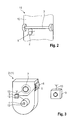
- Fig. 2 shows a door assembly 11 with a door leaf 10, to which a particular in the United States of America usual panic bar 3 is provided as a first actuator.
- the function of the panic bar 3 can be summarized in terms of the present invention so that a pressure or downward movement of the rod 3 from a certain minimum effort allows opening of the door assembly 11.
- a locking housing 2 of a locking device 1 is shown in a first solid representation and in a second, dashed representation. While the panic bar 3 can not be successfully operated by the latch housing 2 in the first solid line, pivoting the latch housing 2 90 degrees clockwise results in release of the panic bar 3.
- Fig. 3 shows a locking housing 2 of a locking device according to the invention 1. This is connected via a shaft 12 with a (not shown) door. On the shaft 12, a drive 4 is mounted. By means of the drive 4, the lock housing 2 can be pivoted in response to an electrical signal of a control unit 5. The control unit 5 is for this purpose via electrical lines to the drive. 4 connected.
- the lock housing 2 has an alarm button 8 under a protective cover 6. The alarm button 8 is connected to the control unit 5 via electrical lines.
- control unit 5 has a transmitting unit whose antenna 13 is set up to transmit and / or receive signals.
- signals may be, for example, the operation of the alarm button 8, in response to which the control unit 5 sends a message via a second, also drawn antenna 13 to a signal generator 9 of a central information system.
- a signal can be sent via the signal generator 9, which causes the control unit 5 to pivot by means of the drive 4, the lock housing 2 in an unlocking position.
- a battery 14 is provided within the control unit. It is obvious that in Fig. 3 shown system could be extended from a (central) signal generator 9 and a locking device 1 according to the invention by further locking devices 1 and / or other signal generator 9.
- a central idea of the present invention is to expand a manually actuable locking housing on a door relative to the prior art in that it is possible to unlock and / or lock the locking housing by means of a drive unit.
- locking device 1 locking device 2 lock housing 3 Actuator of the door 4 drive 5 control unit 6 protective cover 7 push-button 8th Panic button 9 central signaling device 10 door 11 door assembly 12 wave 13 antenna 14 battery
Landscapes
- Business, Economics & Management (AREA)
- Emergency Management (AREA)
- Lock And Its Accessories (AREA)
Applications Claiming Priority (1)
| Application Number | Priority Date | Filing Date | Title |
|---|---|---|---|
| DE201210102027 DE102012102027A1 (de) | 2012-03-09 | 2012-03-09 | Verriegelungsvorrichtung sowie Verriegelungssystem |
Publications (1)
| Publication Number | Publication Date |
|---|---|
| EP2636825A2 true EP2636825A2 (fr) | 2013-09-11 |
Family
ID=47912828
Family Applications (1)
| Application Number | Title | Priority Date | Filing Date |
|---|---|---|---|
| EP13001092.9A Withdrawn EP2636825A2 (fr) | 2012-03-09 | 2013-03-05 | Dispositif et système de verrouillage |
Country Status (2)
| Country | Link |
|---|---|
| EP (1) | EP2636825A2 (fr) |
| DE (1) | DE102012102027A1 (fr) |
Cited By (1)
| Publication number | Priority date | Publication date | Assignee | Title |
|---|---|---|---|---|
| CN106996229A (zh) * | 2017-06-05 | 2017-08-01 | 中车株洲电力机车有限公司 | 司机室门及其机械门锁安全装置、司机室门上锁或解锁的方法 |
-
2012
- 2012-03-09 DE DE201210102027 patent/DE102012102027A1/de not_active Withdrawn
-
2013
- 2013-03-05 EP EP13001092.9A patent/EP2636825A2/fr not_active Withdrawn
Non-Patent Citations (1)
| Title |
|---|
| None |
Cited By (2)
| Publication number | Priority date | Publication date | Assignee | Title |
|---|---|---|---|---|
| CN106996229A (zh) * | 2017-06-05 | 2017-08-01 | 中车株洲电力机车有限公司 | 司机室门及其机械门锁安全装置、司机室门上锁或解锁的方法 |
| CN106996229B (zh) * | 2017-06-05 | 2019-06-07 | 中车株洲电力机车有限公司 | 司机室门及其机械门锁安全装置、司机室门上锁或解锁的方法 |
Also Published As
| Publication number | Publication date |
|---|---|
| DE102012102027A1 (de) | 2013-09-12 |
Similar Documents
| Publication | Publication Date | Title |
|---|---|---|
| EP2518747B1 (fr) | Bouton d'urgence, terminal d'urgence, utilisation d'un affichage dans un bouton d'urgence et procédé d'actionnement d'un bouton d'urgence | |
| EP2568100B2 (fr) | Système pour une porte | |
| DE102012111298A1 (de) | Kraftfahrzeugtürverschluss | |
| DE4033840A1 (de) | Doppeltueroeffner fuer paniktueren mit ruhestrombetaetigung und meldekontakt | |
| EP2058460B1 (fr) | Dispositif de verrouillage anti-effraction pour batiment | |
| EP1967477A1 (fr) | Dispositif d'arrêt d'urgence destiné à l'intégration d'une cabine d'ascenseur d'une installation d'ascenseur | |
| DE102013217377A1 (de) | Elektrisches Kraftfahrzeugschloss mit Notentriegelung | |
| EP1849951B2 (fr) | Installation de porte coulissante | |
| EP2636825A2 (fr) | Dispositif et système de verrouillage | |
| DE102012006357A1 (de) | Pneumatisch gesteuertes Verriegelungssystem für die Cockpit-Tür eines Flugzeugs | |
| EP1160398B1 (fr) | Serrure à commande électrique | |
| DE102013102348A1 (de) | Terminal, insbesondere für Türen | |
| DE102019209103B4 (de) | Vorrichtung zum Öffnen und/oder Schließen eines Bauelementes | |
| DE102015014451A1 (de) | Vorrichtung zum Verhindern des unerlaubten Eindringens an Türen | |
| DE10237729A1 (de) | Schließeinrichtung für eine Fluchttür | |
| EP0405061A1 (fr) | Dispositif pour fixer des clefs de secours | |
| EP2161397A2 (fr) | Dispositif de fixation ou de surveillance de tiges d'actionnement sur des portes de sortie de secours, de portes anti-panique ou analogues | |
| DE19939996B4 (de) | Schliessanlage | |
| EP1580363B1 (fr) | Dispositif pour protection ou surveillance des issues de secours ou similaire | |
| DE1584269C (de) | Sicherungseinnchtung gegen Be raubung an einem Zahltisch | |
| WO2008090205A1 (fr) | Véhicule blindé | |
| DE102019009058A1 (de) | Elektronischer Türriegel mit Fernbedienung zur Verhinderung von Einbrüchen | |
| DE2343594C3 (de) | Schloßriegelbetätigter Alarm-Haupteinschalter in einem Schließblech | |
| DE1069038B (de) | Einbruchssicherer Schrank | |
| DE202015007719U1 (de) | Vorrichtung zum Verhindern des unerlaubten Eindringens an Türen |
Legal Events
| Date | Code | Title | Description |
|---|---|---|---|
| PUAI | Public reference made under article 153(3) epc to a published international application that has entered the european phase |
Free format text: ORIGINAL CODE: 0009012 |
|
| AK | Designated contracting states |
Kind code of ref document: A2 Designated state(s): AL AT BE BG CH CY CZ DE DK EE ES FI FR GB GR HR HU IE IS IT LI LT LU LV MC MK MT NL NO PL PT RO RS SE SI SK SM TR |
|
| AX | Request for extension of the european patent |
Extension state: BA ME |
|
| STAA | Information on the status of an ep patent application or granted ep patent |
Free format text: STATUS: THE APPLICATION HAS BEEN WITHDRAWN |
|
| 18W | Application withdrawn |
Effective date: 20140129 |