EP2636829A2 - Charnière, pièce de charnière et procédé de fabrication d'une pièce de charnière - Google Patents
Charnière, pièce de charnière et procédé de fabrication d'une pièce de charnière Download PDFInfo
- Publication number
- EP2636829A2 EP2636829A2 EP13154929.7A EP13154929A EP2636829A2 EP 2636829 A2 EP2636829 A2 EP 2636829A2 EP 13154929 A EP13154929 A EP 13154929A EP 2636829 A2 EP2636829 A2 EP 2636829A2
- Authority
- EP
- European Patent Office
- Prior art keywords
- hinge
- plastic
- support structure
- hinge part
- bearing pin
- Prior art date
- Legal status (The legal status is an assumption and is not a legal conclusion. Google has not performed a legal analysis and makes no representation as to the accuracy of the status listed.)
- Granted
Links
- 238000004519 manufacturing process Methods 0.000 title claims abstract description 9
- 239000004033 plastic Substances 0.000 claims abstract description 46
- 229920003023 plastic Polymers 0.000 claims abstract description 46
- 229920000049 Carbon (fiber) Polymers 0.000 claims description 11
- 239000004917 carbon fiber Substances 0.000 claims description 11
- VNWKTOKETHGBQD-UHFFFAOYSA-N methane Chemical compound C VNWKTOKETHGBQD-UHFFFAOYSA-N 0.000 claims description 11
- 239000000463 material Substances 0.000 claims description 9
- 239000003365 glass fiber Substances 0.000 claims description 2
- OKTJSMMVPCPJKN-UHFFFAOYSA-N Carbon Chemical compound [C] OKTJSMMVPCPJKN-UHFFFAOYSA-N 0.000 abstract description 2
- 229910052799 carbon Inorganic materials 0.000 abstract description 2
- 239000011152 fibreglass Substances 0.000 description 5
- 150000001875 compounds Chemical class 0.000 description 4
- 238000002347 injection Methods 0.000 description 4
- 239000007924 injection Substances 0.000 description 4
- 238000010276 construction Methods 0.000 description 2
- 238000011161 development Methods 0.000 description 2
- 230000018109 developmental process Effects 0.000 description 2
- 239000002184 metal Substances 0.000 description 2
- 238000000034 method Methods 0.000 description 2
- 229920002430 Fibre-reinforced plastic Polymers 0.000 description 1
- 230000006978 adaptation Effects 0.000 description 1
- 230000005540 biological transmission Effects 0.000 description 1
- 239000004918 carbon fiber reinforced polymer Substances 0.000 description 1
- 239000012876 carrier material Substances 0.000 description 1
- 239000002131 composite material Substances 0.000 description 1
- 238000005520 cutting process Methods 0.000 description 1
- 238000005553 drilling Methods 0.000 description 1
- 238000005538 encapsulation Methods 0.000 description 1
- 239000000835 fiber Substances 0.000 description 1
- 239000011151 fibre-reinforced plastic Substances 0.000 description 1
- 238000003780 insertion Methods 0.000 description 1
- 230000037431 insertion Effects 0.000 description 1
- 230000003993 interaction Effects 0.000 description 1
- 238000002844 melting Methods 0.000 description 1
- 230000008018 melting Effects 0.000 description 1
- 238000004080 punching Methods 0.000 description 1
Images


Classifications
-
- E—FIXED CONSTRUCTIONS
- E05—LOCKS; KEYS; WINDOW OR DOOR FITTINGS; SAFES
- E05D—HINGES OR SUSPENSION DEVICES FOR DOORS, WINDOWS OR WINGS
- E05D9/00—Flaps or sleeves specially designed for making from particular material, e.g. hoop-iron, sheet metal, plastics
-
- E—FIXED CONSTRUCTIONS
- E05—LOCKS; KEYS; WINDOW OR DOOR FITTINGS; SAFES
- E05D—HINGES OR SUSPENSION DEVICES FOR DOORS, WINDOWS OR WINGS
- E05D3/00—Hinges with pins
- E05D3/02—Hinges with pins with one pin
-
- E—FIXED CONSTRUCTIONS
- E05—LOCKS; KEYS; WINDOW OR DOOR FITTINGS; SAFES
- E05D—HINGES OR SUSPENSION DEVICES FOR DOORS, WINDOWS OR WINGS
- E05D5/00—Construction of single parts, e.g. the parts for attachment
- E05D5/02—Parts for attachment, e.g. flaps
- E05D5/06—Bent flaps
- E05D5/062—Bent flaps specially adapted for vehicles
-
- E—FIXED CONSTRUCTIONS
- E05—LOCKS; KEYS; WINDOW OR DOOR FITTINGS; SAFES
- E05D—HINGES OR SUSPENSION DEVICES FOR DOORS, WINDOWS OR WINGS
- E05D9/00—Flaps or sleeves specially designed for making from particular material, e.g. hoop-iron, sheet metal, plastics
- E05D9/005—Flaps or sleeves specially designed for making from particular material, e.g. hoop-iron, sheet metal, plastics from plastics
-
- E—FIXED CONSTRUCTIONS
- E05—LOCKS; KEYS; WINDOW OR DOOR FITTINGS; SAFES
- E05Y—INDEXING SCHEME ASSOCIATED WITH SUBCLASSES E05D AND E05F, RELATING TO CONSTRUCTION ELEMENTS, ELECTRIC CONTROL, POWER SUPPLY, POWER SIGNAL OR TRANSMISSION, USER INTERFACES, MOUNTING OR COUPLING, DETAILS, ACCESSORIES, AUXILIARY OPERATIONS NOT OTHERWISE PROVIDED FOR, APPLICATION THEREOF
- E05Y2800/00—Details, accessories and auxiliary operations not otherwise provided for
- E05Y2800/26—Form or shape
- E05Y2800/29—Form or shape forming a unitary piece with another element
-
- E—FIXED CONSTRUCTIONS
- E05—LOCKS; KEYS; WINDOW OR DOOR FITTINGS; SAFES
- E05Y—INDEXING SCHEME ASSOCIATED WITH SUBCLASSES E05D AND E05F, RELATING TO CONSTRUCTION ELEMENTS, ELECTRIC CONTROL, POWER SUPPLY, POWER SIGNAL OR TRANSMISSION, USER INTERFACES, MOUNTING OR COUPLING, DETAILS, ACCESSORIES, AUXILIARY OPERATIONS NOT OTHERWISE PROVIDED FOR, APPLICATION THEREOF
- E05Y2800/00—Details, accessories and auxiliary operations not otherwise provided for
- E05Y2800/45—Manufacturing
-
- E—FIXED CONSTRUCTIONS
- E05—LOCKS; KEYS; WINDOW OR DOOR FITTINGS; SAFES
- E05Y—INDEXING SCHEME ASSOCIATED WITH SUBCLASSES E05D AND E05F, RELATING TO CONSTRUCTION ELEMENTS, ELECTRIC CONTROL, POWER SUPPLY, POWER SIGNAL OR TRANSMISSION, USER INTERFACES, MOUNTING OR COUPLING, DETAILS, ACCESSORIES, AUXILIARY OPERATIONS NOT OTHERWISE PROVIDED FOR, APPLICATION THEREOF
- E05Y2800/00—Details, accessories and auxiliary operations not otherwise provided for
- E05Y2800/67—Materials; Strength alteration thereof
- E05Y2800/68—Combinations of materials creating distinct article parts
-
- E—FIXED CONSTRUCTIONS
- E05—LOCKS; KEYS; WINDOW OR DOOR FITTINGS; SAFES
- E05Y—INDEXING SCHEME ASSOCIATED WITH SUBCLASSES E05D AND E05F, RELATING TO CONSTRUCTION ELEMENTS, ELECTRIC CONTROL, POWER SUPPLY, POWER SIGNAL OR TRANSMISSION, USER INTERFACES, MOUNTING OR COUPLING, DETAILS, ACCESSORIES, AUXILIARY OPERATIONS NOT OTHERWISE PROVIDED FOR, APPLICATION THEREOF
- E05Y2900/00—Application of doors, windows, wings or fittings thereof
- E05Y2900/10—Application of doors, windows, wings or fittings thereof for buildings or parts thereof
- E05Y2900/13—Type of wing
- E05Y2900/132—Doors
Definitions
- the invention relates to a hinge, in particular a door hinge for motor vehicles, having a hinge pin having a first hinge part and having a cooperating with the bearing pin bearing bush second hinge part, wherein at least one of the hinge parts is at least substantially made of plastic.
- the invention relates to a hinge part for a hinge, in particular as described above, wherein the hinge part is at least substantially made of plastic and carries a bearing pin or a bearing bush.
- the invention relates to a method for producing a hinge part of a hinge, in particular as described above, wherein the hinge part is at least substantially made of a plastic material or plastic and provided with a bearing pin or with a bearing bush.
- Hinges and especially door hinges are widely used in automotive engineering. In addition to the actual task of providing a joint, hinges in motor vehicle construction must meet even further requirements, some of which are also subject to legal provisions. For example, door hinges must be designed such that they can transmit high forces in a crash, to maintain the security cell, and can be solved or separated after the crash, to allow removal of the door to release occupants.
- the publication DE 103 30 162 A1 discloses, for example, a hinge which has two hinge parts, or also referred to as a trade, of which a first carries a bearing pin and a second one cooperating with the bearing pin or the hinge-forming bearing bush. It is proposed to manufacture one of the hinge parts made of a fiber-reinforced plastic.
- the invention has for its object to provide a hinge, a hinge part and a method for producing a hinge part such that the hinge part or the hinge despite high weight has a high load capacity.
- the object underlying the invention is achieved in each case by a hinge with the features of claim 1, by a hinge part with the features of claim 9 and by a method for producing a hinge with the features of claim 10.
- the hinge according to the invention with the features of claim 1 has the advantage that it can be made smaller and lighter overall than a well-known from the prior art hinge to accommodate the same forces safely.
- the carbon fiber reinforced support structure is particularly light and at the same time heavy duty, resulting in the above advantages.
- the load capacity of the hinge thus results largely from the support structure, whereby the requirements for the remaining plastic are lower.
- both hinge parts on a carbon fiber reinforced support structure so that the hinge parts of the hinge acting together are gleichgeartet and so far both have the advantages mentioned above. Overall, this creates a hinge that is lightweight on the one hand and very efficient on the other. Since the shape of the hinge does not change or does not fundamentally change compared to a conventional hinge, the hinge according to the invention continues to meet the requirements for releasability or separability of the hinge parts.
- the respective support structure is formed as a hollow profile.
- the support structure forms a closed support wall, which is particularly resilient.
- the height of the hollow profile corresponds to the height of the base part.
- the support structure designed in this way circumferentially surrounds the plastic of the hinge, whereby the load capacity of the hinge is optimized.
- the plastic forms an inner base part whose outer contour preferably corresponds to the inner contour of the hollow profile in order to produce a firm connection.
- the bearing pin or the bearing bush are held on or in the base part.
- the hollow profile as already mentioned, filled with the plastic, whereby a compact and stable hinge is offered.
- the hollow profile is sprayed with the plastic.
- an adaptation of the base to the hollow profile is achieved in a simple manner.
- the bearing pin and / or the bearing bush are at least partially embedded in the respective plastic.
- the embedding can be done by the injection process or subsequently by introducing the bearing pin and / or the bearing bush in the almost or fully cured plastic.
- the respective base part is provided with corresponding receptacles.
- by the encapsulation of the bearing pin or the bearing bush during the ejection of the hollow profile can ensure a secure attachment of the bearing pin or the bearing bush to the hinge.
- the plastic is preferably fiber-reinforced, in particular glass-fiber reinforced. This increases the strength of the base.
- the carbon fiber reinforced support structure is preferably made as a plastic-based fiber composite. The fact that the support structure and base have a plastic content, these can be firmly connected to each other in a simple manner. In particular, when the temperature of the injected plastic in the hollow profile exceeds the melting point of the plastic of the support structure, a material or cohesive connection of the two elements takes place together, which causes a high load capacity of the respective hinge part.
- the bearing pin and / or the bushing have at least partially in their area surrounding the plastic a corrugation for preventing rotation on their respective outer shell wall.
- the corrugation expediently extends in axial extension of the bearing pin or the bearing bush, whereby a positive rotation in the circumferential direction is offered in a simple manner.
- the corrugation extends over the entire area surrounded by plastic portion of the bearing bush or the bearing pin.
- the bearing pin and / or the bearing bush preferably each have at least one radial projection, which forms at least one contact shoulder in the axial direction.
- the bearing pin and / or bearing bush in an exposed portion of a receptacle for a locking or locking ring, which can be retrofitted or removed.
- the bearing pin and / or the bearing bush can be arranged captively on the respective hinge part. For example, if the bearing pin unilaterally with the radial projection and otherwise provided with the receptacle for the locking ring, so can the bearing pin with the receiving end having introduced into the corresponding opening of the hinge part until the radial projection comes into abutting contact with the hinge part. The then expediently exposed on the other side of the hinge portion recording is then provided with the locking ring, whereby the bearing pin is held in a simple manner total captive on the hinge part.
- the first and / or the second hinge part have at least one threaded bush, which is at least substantially held by the plastic.
- the threaded bushing has, as the name implies, a thread, and is preferably used to attach the respective hinge part to the body or a door of the motor vehicle.
- the threaded bushing preferably has an internal thread and is arranged in a receptacle of the base part.
- the threaded bushing is cup-shaped, so that it can be encapsulated with the plastic mass of the base without plastic enters the threaded area.
- the support structure has an opening in the region of the threaded bush, so that it is accessible from the outside through the support structure.
- the threaded bushing on its outer shell side cooperating with the plastic corrugations to prevent rotation, so when tightening a co-operating with the threaded bush screw for attaching the hinge part high tightening torques can be achieved without the threaded bush dissolves.
- the hinge part according to the invention with the features of claim 9 is characterized in that it has a carbon fiber reinforced support structure. This results in the advantages already mentioned above, in particular with regard to the load capacity and the low weight. Advantageous developments of the hinge part result from the above features and claims.
- the inventive method for producing a hinge part with the features of claim 10 is characterized in that initially a carbon fiber-reinforced Provided support structure and then provided with the plastic compound or with the plastic.
- the plastic compound is applied to the support structure by an injection process or introduced into the support structure.
- the support structure is provided as a hollow profile and the plastic material injected into the hollow profile.
- the support structure is made of a carbon fiber reinforced strand hollow profile, wherein the extruded profile preferably already has the contour of the support structure or where a separated from the strand section brought by a subsequent processing step in the desired structure or shape becomes.
- the front sides of the hollow profile are subsequently processed for example by punching, drilling or cutting operations to obtain the desired hinge part shape.
- the bearing pin or the bearing bush is encapsulated by the plastic, as described above. Overall, a hinge part is thereby produced in a simple manner, which is light and resilient.
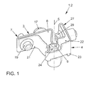
- FIG. 1 shows in a perspective view formed as a door hinge 1 hinge 2 of a motor vehicle not shown here.
- the hinge part 2 has a first hinge part 3 and a second hinge part 4, which are connected to each other in an articulated manner about an axis of rotation 5.
- FIGS. 2A to 2F show the first hinge part 3 in different representations, wherein FIG. 2A shows the hinge part 3 in a perspective view, while FIGS. 2B to 2F Show parts of the hinge part 3.
- the hinge part 3 has a made of plastic, in particular fiberglass reinforced plastic base 6, as in Figure 2C is shown.
- the base part 6 has a - seen in a plan view - substantially angular contour, wherein a leg serves as a connecting flange 7 for fastening the hinge part 3 on the bodywork, in particular on a support column of the motor vehicle.
- the other leg has at its free end a receptacle 8 for a bearing pin 9, as in FIG. 2D is shown on.
- the receptacle 8 has a corrugation 10 which extends axially on the inside of the receptacle 8.
- the bearing pin 9 has at one end 11 a corresponding corrugation 12, which cooperates with the corrugation 10 rotationally inhibited, when the bearing pin 9 is inserted with the end 11 in the receptacle 8.
- the other end 13 of the bearing pin 3 is formed substantially circular cylindrical and is in the inserted state of the bearing pin 9 in the base 6 free.
- the bearing pin 9 has centrally over the entire circumference extending radial projection 14, which serves as Einsteckanschlag or axial stop for the bearing pin 9, and limits the insertion depth of the bearing pin 9 in the receptacle 8.
- Figure 2E shows the base 6 with appropriately inserted bearing pin. 9
- the base 6 has a receptacle for a threaded bushing 15, as in Figure 2F is shown.
- the threaded bush 15 is arranged on the connecting flange 7. It preferably points, as in Figure 2F represented on its outer shell side a corrugation 16, which cooperates with a corresponding corrugation of the not shown here detail of the base 6 as rotation.
- a screw 17 for fixing the hinge part 3 to a body part, in particular on a support bracket of the body of the motor vehicle eincited- or screwed, as in FIG. 1 shown.
- the base part 6 Adjacent to the receptacle for the threaded bushing 15, the base part 6 also in the region of the connection flange 7 on a through hole or opening 18, through which also a screw 19, as in FIG. 1 shown, for fastening the hinge part 3 is feasible.
- the base part 6 is surrounded on its outer shell wall 20 by a support structure 21, the carbon fiber reinforced formed and in FIG. 2B is shown as a single part.
- the carrier material of the support structure 21 is preferably also made of plastic, wherein the contour of the support structure 21 corresponds to the outer contour of the base part 6.
- the support structure 21 thus forms a hollow profile an outer shell of the base 6, as in particular in FIG. 2A shown.
- the support structure 21 can in principle be pushed onto the finished molded base 6.
- the glass fiber reinforced plastic material of the base part 6 is injected into the shaped support structure 21, whereby a tight connection between the base 6 and the support structure 21 is ensured. If the temperature of the injected plastic is selected appropriately, Moreover, a material or material connection between the support structure 21 and the base 6 can also be achieved.
- the support structure 21 has an opening, in particular in FIG. 2A can be seen, so that the screw 19 can penetrate both the support structure 21 and the flange portion of the base 6. Also in the region of the threaded bush 15, the support structure 21 with a corresponding opening, as in particular from FIG. 2B visible, provided.
- FIGS. 3A to 3D show the hinge part 4, which is formed as a door-side hinge part 4, wherein FIG. 3A shows a perspective view of the hinge part 4 and the Figures 3B and 3D Individual parts of the hinge part 4.
- the hinge part 4 a formed from glass fiber reinforced plastic base 22, as in FIG. 3C is shown, and surrounding the base 22 carbon fiber reinforced support structure 23, which is formed as a hollow profile and in FIG. 3B is shown on.
- the hinge part 4 instead of a bearing pin 9, the hinge part 4 on a bearing bush 24, which is made of metal and held in a receptacle 25 of the base 22.
- the support structure 23 is in FIG. 3B shown in perspective.
- the hinge part 4 is produced in that the plastic mass of the base part 22 is preferably injected into the hollow profile of the support structure 23, so that a particularly dense and resilient connection is formed. Particularly preferably, the injection temperature is selected such that a cohesive connection between base 22 and support structure 23 is formed.
- the hinge part 4 also has a connection flange 27, which serves for fastening the hinge part 4 to a door of the motor vehicle.
- connection flange 27 which is a leg of the angularly formed hinge part 4
- an opening 28 for receiving a screw 29, as in FIG. 1 shown provided in the connecting flange 27, which is a leg of the angularly formed hinge part 4, an opening 28 for receiving a screw 29, as in FIG. 1 shown, provided.
- the bearing bush 24, which is held in a form-fitting manner in the base part 22, has a circular cylindrical shape, its inner diameter substantially corresponding to the outer diameter of the end 13 of the bearing bolt 9 corresponds, so that bushing 24 and bearing pin 9 as the axis of rotation 5 forming pivot or rotary joint are merge to the hinge 2 according to FIG. 1 to build.
- the bearing pin 9 rotatably rests in the bearing bush 24.
- FIG. 3A it is also conceivable to provide recesses in the support structure 23 or also 21, through which the injected plastic compound of the respective base part 6 or 22 can pass outward from the hollow profile of the respective support structure 21, 23, for example as in FIG FIG. 3A shown to form an outwardly projecting rib 29.
- the metal parts are already encapsulated with the injection of the glass-fiber-reinforced plastic material in the respective support structure 21, 23, whereby a particularly secure attachment and a particularly resilient hinge 2 is offered in total.
Landscapes
- Engineering & Computer Science (AREA)
- Mechanical Engineering (AREA)
- Body Structure For Vehicles (AREA)
- Injection Moulding Of Plastics Or The Like (AREA)
Applications Claiming Priority (1)
| Application Number | Priority Date | Filing Date | Title |
|---|---|---|---|
| DE102012004810A DE102012004810A1 (de) | 2012-03-08 | 2012-03-08 | Scharnier, Scharnierteil und Verfahren zur Herstellung eines Scharnierteils |
Publications (3)
| Publication Number | Publication Date |
|---|---|
| EP2636829A2 true EP2636829A2 (fr) | 2013-09-11 |
| EP2636829A3 EP2636829A3 (fr) | 2017-12-27 |
| EP2636829B1 EP2636829B1 (fr) | 2019-05-22 |
Family
ID=47739108
Family Applications (1)
| Application Number | Title | Priority Date | Filing Date |
|---|---|---|---|
| EP13154929.7A Active EP2636829B1 (fr) | 2012-03-08 | 2013-02-12 | Charnière, pièce de charnière et procédé de fabrication d'une pièce de charnière |
Country Status (2)
| Country | Link |
|---|---|
| EP (1) | EP2636829B1 (fr) |
| DE (1) | DE102012004810A1 (fr) |
Families Citing this family (5)
| Publication number | Priority date | Publication date | Assignee | Title |
|---|---|---|---|---|
| DE102013216500B4 (de) * | 2013-08-20 | 2020-09-10 | Bayerische Motoren Werke Aktiengesellschaft | Scharnier zum Halten eines Flügelelements sowie Halteanordnung eines Flügelelements an einem Aufbauteil eines Aufbaus eines Kraftwagens |
| DE202013008268U1 (de) | 2013-09-19 | 2013-10-08 | Edscha Engineering Gmbh | Kraftfahrzeugscharnier |
| DE102013015484B3 (de) * | 2013-09-19 | 2014-07-10 | Edscha Engineering Gmbh | Kraftfahrzeugscharnier |
| DE102015115162B4 (de) | 2015-09-09 | 2022-10-27 | Dr. Ing. H.C. F. Porsche Aktiengesellschaft | Scharnier für einen Deckel eines Kraftfahrzeugs |
| DE102016108367B4 (de) | 2016-05-04 | 2022-06-09 | Edscha Engineering Gmbh | Fahrzeugscharnier und Verfahren zur Herstellung eines Befestigungsteils des Fahrzeugscharniers |
Citations (1)
| Publication number | Priority date | Publication date | Assignee | Title |
|---|---|---|---|---|
| DE10330162A1 (de) | 2003-07-04 | 2005-01-27 | Daimlerchrysler Ag | Scharnier mit integrierter Feststell- und Bremsfunktion |
Family Cites Families (2)
| Publication number | Priority date | Publication date | Assignee | Title |
|---|---|---|---|---|
| DE3730329A1 (de) * | 1987-09-10 | 1989-03-30 | Hackelsberger Mussbach Metall | Scharnier fuer kraftfahrzeugseitentueren |
| EP2330267B1 (fr) * | 2010-08-25 | 2013-12-25 | Metalsa Automotive GmbH | Charnière de capot de véhicule |
-
2012
- 2012-03-08 DE DE102012004810A patent/DE102012004810A1/de not_active Withdrawn
-
2013
- 2013-02-12 EP EP13154929.7A patent/EP2636829B1/fr active Active
Patent Citations (1)
| Publication number | Priority date | Publication date | Assignee | Title |
|---|---|---|---|---|
| DE10330162A1 (de) | 2003-07-04 | 2005-01-27 | Daimlerchrysler Ag | Scharnier mit integrierter Feststell- und Bremsfunktion |
Also Published As
| Publication number | Publication date |
|---|---|
| DE102012004810A1 (de) | 2013-09-12 |
| EP2636829A3 (fr) | 2017-12-27 |
| EP2636829B1 (fr) | 2019-05-22 |
Similar Documents
| Publication | Publication Date | Title |
|---|---|---|
| DE102010041791B4 (de) | Fahrzeugbauteil | |
| EP2759423B1 (fr) | Bras oscillant transversal en plastique renforcé en fibres pour une suspension de roue d'un véhicule | |
| DE69307077T2 (de) | Kugelgelenk und Herstellungsverfahren dafür | |
| DE69225629T2 (de) | Kombination eines Querstabilisators und eines Befestigungselementes | |
| EP3692269B1 (fr) | Accouplement angulaire | |
| EP2636829B1 (fr) | Charnière, pièce de charnière et procédé de fabrication d'une pièce de charnière | |
| EP3042090B1 (fr) | Insert d'assemblage ainsi que procédé d'inclusion et procédé de fabrication correspondant | |
| WO2014057027A1 (fr) | Composant avec bouchon d'étanchéité et procédé de moulage d'un insert de composant | |
| DE102018202307A1 (de) | Lenker für eine Radaufhängung | |
| WO2020078643A1 (fr) | Composant de véhicule pour un véhicule automobile et procédé de fabrication d'un composant de véhicule de ce type | |
| WO2013050218A1 (fr) | Ensemble de raccordement pour un véhicule | |
| DE102007036554B4 (de) | Deckel-Lager-Anordnung und Verfahren zum Montieren einer Aktuatorwelle | |
| EP0972957A2 (fr) | Joint à rotule et son procédé de fabrication | |
| WO2009010053A1 (fr) | Bras de suspension hybride destiné à un véhicule | |
| DE102016210123A1 (de) | Versteifungsbauteil für eine Struktur eines Luft- oder Raumfahrzeugs, Luft- oder Raumfahrzeug, sowie Verfahren | |
| DE102010054094B3 (de) | Krafteinleitungselement sowie Verwendung desselben für ein Faser-Kunststoff-Verbund-Bauteil | |
| DE102017115071B4 (de) | Radlagereinheit | |
| WO2023094508A1 (fr) | Bielle d'accouplement et son procédé de production | |
| EP3581743A1 (fr) | Biellette pour une unité d'arrêt de porte, unité d'arrêt de porte pourvue de biellette, porte de véhicule pourvue d'unité d'arrêt de porte ainsi que véhicule pourvu de portes latérales de véhicule pourvues d'unité d'arrêt de porte | |
| EP2423010A2 (fr) | Guide d'essieu de véhicule et douille en caoutchouc d'acier pour l'utilisation dans un volant de véhicule | |
| DE102004061057A1 (de) | Kugelgelenkverbindung zwischen einem Zapfen und einem Befestigungsteil | |
| EP2876980B1 (fr) | Boîtier ayant une pièce d'insertion en matière plastique | |
| DE102019116034A1 (de) | Kugelgelenk und Verfahren zu dessen Herstellung | |
| EP3085864B1 (fr) | Dispositif de fermeture pour une porte ou une trappe | |
| DE102014207600B4 (de) | Verfahren zum Herstellen eines Getriebegehäuses sowie Getriebe mit einem Getriebegehäuse |
Legal Events
| Date | Code | Title | Description |
|---|---|---|---|
| PUAI | Public reference made under article 153(3) epc to a published international application that has entered the european phase |
Free format text: ORIGINAL CODE: 0009012 |
|
| AK | Designated contracting states |
Kind code of ref document: A2 Designated state(s): AL AT BE BG CH CY CZ DE DK EE ES FI FR GB GR HR HU IE IS IT LI LT LU LV MC MK MT NL NO PL PT RO RS SE SI SK SM TR |
|
| AX | Request for extension of the european patent |
Extension state: BA ME |
|
| PUAL | Search report despatched |
Free format text: ORIGINAL CODE: 0009013 |
|
| AK | Designated contracting states |
Kind code of ref document: A3 Designated state(s): AL AT BE BG CH CY CZ DE DK EE ES FI FR GB GR HR HU IE IS IT LI LT LU LV MC MK MT NL NO PL PT RO RS SE SI SK SM TR |
|
| AX | Request for extension of the european patent |
Extension state: BA ME |
|
| RIC1 | Information provided on ipc code assigned before grant |
Ipc: E05D 9/00 20060101ALI20171123BHEP Ipc: E05D 3/02 20060101AFI20171123BHEP Ipc: E05D 5/06 20060101ALI20171123BHEP |
|
| STAA | Information on the status of an ep patent application or granted ep patent |
Free format text: STATUS: REQUEST FOR EXAMINATION WAS MADE |
|
| 17P | Request for examination filed |
Effective date: 20180627 |
|
| RBV | Designated contracting states (corrected) |
Designated state(s): AL AT BE BG CH CY CZ DE DK EE ES FI FR GB GR HR HU IE IS IT LI LT LU LV MC MK MT NL NO PL PT RO RS SE SI SK SM TR |
|
| GRAP | Despatch of communication of intention to grant a patent |
Free format text: ORIGINAL CODE: EPIDOSNIGR1 |
|
| STAA | Information on the status of an ep patent application or granted ep patent |
Free format text: STATUS: GRANT OF PATENT IS INTENDED |
|
| INTG | Intention to grant announced |
Effective date: 20190108 |
|
| GRAS | Grant fee paid |
Free format text: ORIGINAL CODE: EPIDOSNIGR3 |
|
| GRAA | (expected) grant |
Free format text: ORIGINAL CODE: 0009210 |
|
| STAA | Information on the status of an ep patent application or granted ep patent |
Free format text: STATUS: THE PATENT HAS BEEN GRANTED |
|
| AK | Designated contracting states |
Kind code of ref document: B1 Designated state(s): AL AT BE BG CH CY CZ DE DK EE ES FI FR GB GR HR HU IE IS IT LI LT LU LV MC MK MT NL NO PL PT RO RS SE SI SK SM TR |
|
| REG | Reference to a national code |
Ref country code: GB Ref legal event code: FG4D Free format text: NOT ENGLISH |
|
| REG | Reference to a national code |
Ref country code: CH Ref legal event code: EP |
|
| REG | Reference to a national code |
Ref country code: IE Ref legal event code: FG4D Free format text: LANGUAGE OF EP DOCUMENT: GERMAN |
|
| REG | Reference to a national code |
Ref country code: DE Ref legal event code: R096 Ref document number: 502013012863 Country of ref document: DE |
|
| REG | Reference to a national code |
Ref country code: AT Ref legal event code: REF Ref document number: 1136311 Country of ref document: AT Kind code of ref document: T Effective date: 20190615 |
|
| REG | Reference to a national code |
Ref country code: NL Ref legal event code: MP Effective date: 20190522 |
|
| REG | Reference to a national code |
Ref country code: LT Ref legal event code: MG4D |
|
| PG25 | Lapsed in a contracting state [announced via postgrant information from national office to epo] |
Ref country code: AL Free format text: LAPSE BECAUSE OF FAILURE TO SUBMIT A TRANSLATION OF THE DESCRIPTION OR TO PAY THE FEE WITHIN THE PRESCRIBED TIME-LIMIT Effective date: 20190522 Ref country code: ES Free format text: LAPSE BECAUSE OF FAILURE TO SUBMIT A TRANSLATION OF THE DESCRIPTION OR TO PAY THE FEE WITHIN THE PRESCRIBED TIME-LIMIT Effective date: 20190522 Ref country code: PT Free format text: LAPSE BECAUSE OF FAILURE TO SUBMIT A TRANSLATION OF THE DESCRIPTION OR TO PAY THE FEE WITHIN THE PRESCRIBED TIME-LIMIT Effective date: 20190922 Ref country code: NL Free format text: LAPSE BECAUSE OF FAILURE TO SUBMIT A TRANSLATION OF THE DESCRIPTION OR TO PAY THE FEE WITHIN THE PRESCRIBED TIME-LIMIT Effective date: 20190522 Ref country code: NO Free format text: LAPSE BECAUSE OF FAILURE TO SUBMIT A TRANSLATION OF THE DESCRIPTION OR TO PAY THE FEE WITHIN THE PRESCRIBED TIME-LIMIT Effective date: 20190822 Ref country code: LT Free format text: LAPSE BECAUSE OF FAILURE TO SUBMIT A TRANSLATION OF THE DESCRIPTION OR TO PAY THE FEE WITHIN THE PRESCRIBED TIME-LIMIT Effective date: 20190522 Ref country code: FI Free format text: LAPSE BECAUSE OF FAILURE TO SUBMIT A TRANSLATION OF THE DESCRIPTION OR TO PAY THE FEE WITHIN THE PRESCRIBED TIME-LIMIT Effective date: 20190522 Ref country code: SE Free format text: LAPSE BECAUSE OF FAILURE TO SUBMIT A TRANSLATION OF THE DESCRIPTION OR TO PAY THE FEE WITHIN THE PRESCRIBED TIME-LIMIT Effective date: 20190522 Ref country code: HR Free format text: LAPSE BECAUSE OF FAILURE TO SUBMIT A TRANSLATION OF THE DESCRIPTION OR TO PAY THE FEE WITHIN THE PRESCRIBED TIME-LIMIT Effective date: 20190522 |
|
| PG25 | Lapsed in a contracting state [announced via postgrant information from national office to epo] |
Ref country code: RS Free format text: LAPSE BECAUSE OF FAILURE TO SUBMIT A TRANSLATION OF THE DESCRIPTION OR TO PAY THE FEE WITHIN THE PRESCRIBED TIME-LIMIT Effective date: 20190522 Ref country code: LV Free format text: LAPSE BECAUSE OF FAILURE TO SUBMIT A TRANSLATION OF THE DESCRIPTION OR TO PAY THE FEE WITHIN THE PRESCRIBED TIME-LIMIT Effective date: 20190522 Ref country code: GR Free format text: LAPSE BECAUSE OF FAILURE TO SUBMIT A TRANSLATION OF THE DESCRIPTION OR TO PAY THE FEE WITHIN THE PRESCRIBED TIME-LIMIT Effective date: 20190823 Ref country code: BG Free format text: LAPSE BECAUSE OF FAILURE TO SUBMIT A TRANSLATION OF THE DESCRIPTION OR TO PAY THE FEE WITHIN THE PRESCRIBED TIME-LIMIT Effective date: 20190822 |
|
| PG25 | Lapsed in a contracting state [announced via postgrant information from national office to epo] |
Ref country code: DK Free format text: LAPSE BECAUSE OF FAILURE TO SUBMIT A TRANSLATION OF THE DESCRIPTION OR TO PAY THE FEE WITHIN THE PRESCRIBED TIME-LIMIT Effective date: 20190522 Ref country code: EE Free format text: LAPSE BECAUSE OF FAILURE TO SUBMIT A TRANSLATION OF THE DESCRIPTION OR TO PAY THE FEE WITHIN THE PRESCRIBED TIME-LIMIT Effective date: 20190522 Ref country code: CZ Free format text: LAPSE BECAUSE OF FAILURE TO SUBMIT A TRANSLATION OF THE DESCRIPTION OR TO PAY THE FEE WITHIN THE PRESCRIBED TIME-LIMIT Effective date: 20190522 Ref country code: RO Free format text: LAPSE BECAUSE OF FAILURE TO SUBMIT A TRANSLATION OF THE DESCRIPTION OR TO PAY THE FEE WITHIN THE PRESCRIBED TIME-LIMIT Effective date: 20190522 Ref country code: SK Free format text: LAPSE BECAUSE OF FAILURE TO SUBMIT A TRANSLATION OF THE DESCRIPTION OR TO PAY THE FEE WITHIN THE PRESCRIBED TIME-LIMIT Effective date: 20190522 |
|
| REG | Reference to a national code |
Ref country code: DE Ref legal event code: R097 Ref document number: 502013012863 Country of ref document: DE |
|
| PG25 | Lapsed in a contracting state [announced via postgrant information from national office to epo] |
Ref country code: IT Free format text: LAPSE BECAUSE OF FAILURE TO SUBMIT A TRANSLATION OF THE DESCRIPTION OR TO PAY THE FEE WITHIN THE PRESCRIBED TIME-LIMIT Effective date: 20190522 Ref country code: SM Free format text: LAPSE BECAUSE OF FAILURE TO SUBMIT A TRANSLATION OF THE DESCRIPTION OR TO PAY THE FEE WITHIN THE PRESCRIBED TIME-LIMIT Effective date: 20190522 |
|
| PLBE | No opposition filed within time limit |
Free format text: ORIGINAL CODE: 0009261 |
|
| STAA | Information on the status of an ep patent application or granted ep patent |
Free format text: STATUS: NO OPPOSITION FILED WITHIN TIME LIMIT |
|
| PG25 | Lapsed in a contracting state [announced via postgrant information from national office to epo] |
Ref country code: TR Free format text: LAPSE BECAUSE OF FAILURE TO SUBMIT A TRANSLATION OF THE DESCRIPTION OR TO PAY THE FEE WITHIN THE PRESCRIBED TIME-LIMIT Effective date: 20190522 |
|
| 26N | No opposition filed |
Effective date: 20200225 |
|
| PG25 | Lapsed in a contracting state [announced via postgrant information from national office to epo] |
Ref country code: PL Free format text: LAPSE BECAUSE OF FAILURE TO SUBMIT A TRANSLATION OF THE DESCRIPTION OR TO PAY THE FEE WITHIN THE PRESCRIBED TIME-LIMIT Effective date: 20190522 |
|
| PG25 | Lapsed in a contracting state [announced via postgrant information from national office to epo] |
Ref country code: SI Free format text: LAPSE BECAUSE OF FAILURE TO SUBMIT A TRANSLATION OF THE DESCRIPTION OR TO PAY THE FEE WITHIN THE PRESCRIBED TIME-LIMIT Effective date: 20190522 |
|
| REG | Reference to a national code |
Ref country code: CH Ref legal event code: PL |
|
| GBPC | Gb: european patent ceased through non-payment of renewal fee |
Effective date: 20200212 |
|
| REG | Reference to a national code |
Ref country code: BE Ref legal event code: MM Effective date: 20200229 |
|
| PG25 | Lapsed in a contracting state [announced via postgrant information from national office to epo] |
Ref country code: LU Free format text: LAPSE BECAUSE OF NON-PAYMENT OF DUE FEES Effective date: 20200212 Ref country code: MC Free format text: LAPSE BECAUSE OF FAILURE TO SUBMIT A TRANSLATION OF THE DESCRIPTION OR TO PAY THE FEE WITHIN THE PRESCRIBED TIME-LIMIT Effective date: 20190522 |
|
| PG25 | Lapsed in a contracting state [announced via postgrant information from national office to epo] |
Ref country code: LI Free format text: LAPSE BECAUSE OF NON-PAYMENT OF DUE FEES Effective date: 20200229 Ref country code: CH Free format text: LAPSE BECAUSE OF NON-PAYMENT OF DUE FEES Effective date: 20200229 |
|
| PG25 | Lapsed in a contracting state [announced via postgrant information from national office to epo] |
Ref country code: IE Free format text: LAPSE BECAUSE OF NON-PAYMENT OF DUE FEES Effective date: 20200212 Ref country code: FR Free format text: LAPSE BECAUSE OF NON-PAYMENT OF DUE FEES Effective date: 20200229 Ref country code: GB Free format text: LAPSE BECAUSE OF NON-PAYMENT OF DUE FEES Effective date: 20200212 |
|
| PG25 | Lapsed in a contracting state [announced via postgrant information from national office to epo] |
Ref country code: BE Free format text: LAPSE BECAUSE OF NON-PAYMENT OF DUE FEES Effective date: 20200229 |
|
| REG | Reference to a national code |
Ref country code: AT Ref legal event code: MM01 Ref document number: 1136311 Country of ref document: AT Kind code of ref document: T Effective date: 20200212 |
|
| PG25 | Lapsed in a contracting state [announced via postgrant information from national office to epo] |
Ref country code: AT Free format text: LAPSE BECAUSE OF NON-PAYMENT OF DUE FEES Effective date: 20200212 |
|
| PGFP | Annual fee paid to national office [announced via postgrant information from national office to epo] |
Ref country code: DE Payment date: 20210228 Year of fee payment: 9 |
|
| PG25 | Lapsed in a contracting state [announced via postgrant information from national office to epo] |
Ref country code: MT Free format text: LAPSE BECAUSE OF FAILURE TO SUBMIT A TRANSLATION OF THE DESCRIPTION OR TO PAY THE FEE WITHIN THE PRESCRIBED TIME-LIMIT Effective date: 20190522 Ref country code: CY Free format text: LAPSE BECAUSE OF FAILURE TO SUBMIT A TRANSLATION OF THE DESCRIPTION OR TO PAY THE FEE WITHIN THE PRESCRIBED TIME-LIMIT Effective date: 20190522 |
|
| PG25 | Lapsed in a contracting state [announced via postgrant information from national office to epo] |
Ref country code: MK Free format text: LAPSE BECAUSE OF FAILURE TO SUBMIT A TRANSLATION OF THE DESCRIPTION OR TO PAY THE FEE WITHIN THE PRESCRIBED TIME-LIMIT Effective date: 20190522 Ref country code: IS Free format text: LAPSE BECAUSE OF FAILURE TO SUBMIT A TRANSLATION OF THE DESCRIPTION OR TO PAY THE FEE WITHIN THE PRESCRIBED TIME-LIMIT Effective date: 20190922 |
|
| REG | Reference to a national code |
Ref country code: DE Ref legal event code: R119 Ref document number: 502013012863 Country of ref document: DE |
|
| PG25 | Lapsed in a contracting state [announced via postgrant information from national office to epo] |
Ref country code: DE Free format text: LAPSE BECAUSE OF NON-PAYMENT OF DUE FEES Effective date: 20220901 |