EP2636830A2 - Fixation de penture, ensemble avec fixation de penture et penture ainsi qu'agencement de porte - Google Patents
Fixation de penture, ensemble avec fixation de penture et penture ainsi qu'agencement de porte Download PDFInfo
- Publication number
- EP2636830A2 EP2636830A2 EP13155493.3A EP13155493A EP2636830A2 EP 2636830 A2 EP2636830 A2 EP 2636830A2 EP 13155493 A EP13155493 A EP 13155493A EP 2636830 A2 EP2636830 A2 EP 2636830A2
- Authority
- EP
- European Patent Office
- Prior art keywords
- door hinge
- fastening
- hollow profile
- door
- end plate
- Prior art date
- Legal status (The legal status is an assumption and is not a legal conclusion. Google has not performed a legal analysis and makes no representation as to the accuracy of the status listed.)
- Granted
Links
Images


Classifications
-
- E—FIXED CONSTRUCTIONS
- E05—LOCKS; KEYS; WINDOW OR DOOR FITTINGS; SAFES
- E05D—HINGES OR SUSPENSION DEVICES FOR DOORS, WINDOWS OR WINGS
- E05D5/00—Construction of single parts, e.g. the parts for attachment
- E05D5/02—Parts for attachment, e.g. flaps
- E05D5/0215—Parts for attachment, e.g. flaps for attachment to profile members or the like
- E05D5/0223—Parts for attachment, e.g. flaps for attachment to profile members or the like with parts, e.g. screws, extending through the profile wall or engaging profile grooves
- E05D5/023—Parts for attachment, e.g. flaps for attachment to profile members or the like with parts, e.g. screws, extending through the profile wall or engaging profile grooves with parts extending through the profile wall
-
- E—FIXED CONSTRUCTIONS
- E05—LOCKS; KEYS; WINDOW OR DOOR FITTINGS; SAFES
- E05D—HINGES OR SUSPENSION DEVICES FOR DOORS, WINDOWS OR WINGS
- E05D3/00—Hinges with pins
- E05D3/06—Hinges with pins with two or more pins
- E05D3/18—Hinges with pins with two or more pins with sliding pins or guides
- E05D3/186—Scissors hinges, with two crossing levers and five parallel pins
-
- E—FIXED CONSTRUCTIONS
- E05—LOCKS; KEYS; WINDOW OR DOOR FITTINGS; SAFES
- E05Y—INDEXING SCHEME ASSOCIATED WITH SUBCLASSES E05D AND E05F, RELATING TO CONSTRUCTION ELEMENTS, ELECTRIC CONTROL, POWER SUPPLY, POWER SIGNAL OR TRANSMISSION, USER INTERFACES, MOUNTING OR COUPLING, DETAILS, ACCESSORIES, AUXILIARY OPERATIONS NOT OTHERWISE PROVIDED FOR, APPLICATION THEREOF
- E05Y2900/00—Application of doors, windows, wings or fittings thereof
- E05Y2900/10—Application of doors, windows, wings or fittings thereof for buildings or parts thereof
- E05Y2900/13—Type of wing
- E05Y2900/132—Doors
Definitions
- the invention relates to a door hinge fastening for fastening a door hinge to a hollow profile, with an end plate provided for abutment on a first outer surface of the hollow profile on a first side and with an opposite second side on which the door hinge is to be arranged, and with at least one connecting element.
- the door hinge attachment includes two or more fasteners attached to the end plate.
- the invention also relates to an assembly comprising at least one door hinge fastening and a door hinge, and a door assembly having at least one door hinge fastening, a door hinge and a hollow profile of a door frame or a sash.
- the gap between the door leaf and the door frame is formed on the second outer surface, while the wall is connected to the first outer surface of the hollow profile in a door frame and the filling in the case of a door leaf.
- the concealed in the assembled state end plate is previously mounted on the hollow profile accordingly.
- transverse bores are introduced into the hollow profile at a suitable height, which extend from the first side to the second side.
- the door hinge attachment should be arranged without a significant play in the associated holes in the hollow profile.
- the DE 299 22 023 U1 on the other hand describes a door hinge fastening, which has starting from an end plate a plurality of connecting elements, which are each adjustable in length.
- an inner sleeve and an outer sleeve are provided in each case, which are connected to one another via a thread.
- This can be further screwed in or out, so that the bridging of a different distance is possible.
- the entire assembly is mounted by the concealed in the assembled state first outer surface of the hollow profile, so the outer sleeves must be made without a collar.
- the outer sleeves can then be positioned with a tool such that they are supported on the second outer surface radially to the holes of such hollow profile, but without protruding outward.
- a tool such that they are supported on the second outer surface radially to the holes of such hollow profile, but without protruding outward.
- the main goal is a rigid support through the door hinge fastening in the longitudinal direction allow so that the hollow profile can not be compressed when tightening fastening screws.
- the invention has for its object to provide a door hinge attachment for attaching a door hinge to a hollow profile, which is suitable in a simple configuration for different widths hollow sections. It should also be given an assembly and a door assembly having such a door hinge attachment.
- the object is achieved in that on the second side a separate passage sleeve is provided for the fastening screw, wherein the passage sleeve on its side facing away from the end plate a radially projecting collar for support on a second outer surface of the Hollow profile has.
- At least two connecting elements are arranged on the end plate, which are provided with a corresponding number of connecting screws interact. By at least two connecting elements and a rotation of the end plate is prevented.
- a bore in the transverse direction of the hollow profile is produced with a uniform diameter for receiving the door hinge fastening, so that the openings in the first outer surface and the second outer surface have the same diameter.
- the connecting element at least on a subsequent to the end plate section, the same outer diameter as the passage sleeve outside the collar. The outer diameter of the passage sleeve outside of the collar or on the subsequent to the end plate portion of the connecting element are then chosen so that without considerable play an arrangement can be made on the hollow profile.
- the invention remains in the mounted state of the band assembly on the hollow profile between the at least one connecting element and the associated passage sleeve a distance which is bridged by the associated fastening screw.
- the gap is correspondingly small, wherein the fastening screw engages deep in the sleeve-shaped end portion of the connecting element.
- both can have a circular-cylindrical outer surface and in particular also a same outer diameter.
- the passage sleeve is provided to center the door hinge attachment to the second outer surface. If, according to the preferred embodiment described above, the passage sleeve ends at a distance from the associated connecting element, the centering takes place via the fixing screw guided through the fastening screw, for which purpose the inner diameter of the passage sleeve is adapted to the outer diameter of the fastening screw.
- the grommet is to be made as short as possible in order to allow the widest possible adaptation to different width hollow sections. It is only necessary to ensure that the passage sleeve is reliably supported with the section adjoining the end-side collar in the radial direction relative to the associated opening in the second outer surface of the hollow profile. Against this background, it is preferred if the passage sleeve has a length between 3 mm and 15 mm, particularly preferably between 4 mm and 10 mm, for example, a length of about 6 mm.
- connection elements and sleeves with a continuous internal thread, wherein on the one hand, the attachment to the end plate and wherein on the other side engage the mounting screws.
- the invention is also an assembly comprising at least one configured as described above Mosbandbefest Trent and a door hinge, wherein the hinge on a mounting portion has a through hole for the fastening screw and wherein the through hole on an intended as a contact surface side of the mounting portion an extension for receiving the radially projecting Collar of the associated passage sleeve has.
- the door hinge itself must be adapted to be able to be mounted with the described door hinge attachment. Without the described extension for receiving the radially projecting collar of the mounting portion would rest only on the collar and thus at least slightly protrude from the hollow profiles themselves.
- the fastening section may be a substantially flat hinge strap or even end sections of a main body of the door hinge.
- the door hinge is fixed with a plurality of fastening screws on the hollow profile.
- a correspondingly configured plate can be provided on which an associated connecting element is provided for each fastening screw.
- at least two door hinge fasteners are provided for fastening the door hinge to the hollow profile.
- the door hinge has a base, it may be at an upper end as well as at a lower end each of the base body attachment portions may be provided, each attachment portion is associated with a door hinge attachment.
- the invention also provides a door arrangement with at least one door hinge fastening designed as described above, a door hinge and a hollow profile of a door frame or a door frame.
- the door hinge is arranged with the at least one door hinge attachment to the hollow profile, wherein the door hinge attachment and the door hinge can form the assembly described above.
- the end plate of the door hinge attachment rests against a first outer surface of the hollow profile, wherein a fastening portion of the door hinge rests with a contact surface on a second outer surface of the hollow profile. Between the connecting element and the associated passage sleeve thereby remains bridged by the fastening screw distance.
- the door hinge fastening according to the invention is suitable for the arrangement on hollow sections of different widths.
- the connecting element may extend over 60% to 85% of the distance between the first outer surface and the second outer surface.
- the invention is based on the finding that a very firm tightening the mounting screws is not necessary, because by the largely play-free arrangement of the at least one connecting element and the associated sleeve in openings of the two outer surfaces, a force support in the vertical direction.
- the end plate and the contact surface extends between the end plate and the contact surface at least one inner web of the hollow profile, which connects the first outer surface with the second outer surface.
- the end plate and the contact surface cover at least one inner web which stabilizes the hollow profile, as a result of which tensile forces can be absorbed which are applied by the fastening screws.
- the end plate and the abutment surface are thus sufficiently ready to be carried out in a thickness direction of the door assembly.
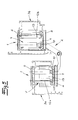
- the Fig. 1 shows a door hinge fastener 1 for fastening a door hinge 2 on a hollow profile 3a. Of the door hinge 2, only a fastening portion 4 is shown by way of example, which has through-holes 5.
- the door hinge fastener 1 has an end plate 6 provided for abutment against a first outer surface of the hollow profile 3a on a first side.
- two connecting elements 7 are screwed, each having a sleeve-shaped end portion 8 at their opposite ends of the end plate 6.
- fastening screws 9 are arranged, which are screwed into the sleeve-shaped end portions 8 on the second side by separate through sleeves 10 therethrough.
- the through sleeves 10 have on their side facing away from the end plate 6 each a radially projecting collar 11 for support on a second outer surface of the hollow profile 3a.
- the arrangement of the door hinge attachment 1 on the hollow profile 3a is in the Fig. 2 shown. It can be seen that the attachment portion 4 has at the through holes 5 a collar 11 receiving broadening, so that the attachment portion 4 can abut with a contact surface on the second outer surface of the hollow profile 3a.
- the through sleeves 10 have outside of the collar 11 an outer diameter which corresponds to the outer diameter of the connecting elements 7. This outer diameter is set so that it corresponds to the size of holes in the hollow section 3a, so that via the door hinge attachment 1 a largely backlash-free support of the door hinge 2 takes place on the hollow profile 3a.
- the fastening screws 9 are passed through the through sleeves 10 and engage directly in the connecting elements 7, wherein between the connecting elements 7 and the respective associated through sleeves 10, a gap S remains.
- the through sleeves 10 can be made relatively short, because they cause only a radial support of the fastening screws 9 on the hollow profile 3a.
- the length of the through sleeves 10 may for example be between 4 mm and 10 mm, in particular about 6 mm.
- the connecting elements 7 are made longer, wherein in the embodiment according to the Fig. 2 with a comparatively narrow hollow profile 3a, the fastening screws 9 engage far into the sleeve-shaped end section 8 of the connecting elements 7.
- the Fig. 3 shows the arrangement of the door hinge attachment 1 to a wider hollow profile 3a '.
- the length of the sleeve-shaped end portions 8 and the fastening screws 9 is chosen so that even with a wider hollow profile 3a 'a sufficient connection between the fastening screws 9 and the connecting elements 7 is ensured.
- the connecting elements 7 extend over 60% to 85% of the distance between the first outer surface and the second outer surface of the respective hollow profile 3a, 3a'.
- Fig. 1 to 3 show an embodiment in which the door hinge attachment 1 has two connecting elements 7.
- the door hinge attachment 1 has two connecting elements 7.
- embodiments with only one connecting element 7 or with more than two connecting elements 7 are possible.
- at least two connecting elements. 7 there is the advantage that the end plate 6 is secured against rotation or co-rotation when tightening the mounting screws 9.
- FIGS. 2 and 3 It can also be seen that the end plate 6 and the contact surface of the mounting portion 4 are expediently to be dimensioned so wide that two inner webs 12a, 12b of the hollow profile 3a, 3a 'extend between these two parts.
- the tensile forces applied by the fastening screws 9 can thus be absorbed by the hollow profile 3a, 3a '. Since a gap S should always remain between the connecting elements 7 and the associated through sleeves 10 according to the exemplary embodiment, direct support in the longitudinal direction between these two parts is not provided.
- the Fig. 4 and 5 show in a perspective view and in a plan view with cut hollow sections of the cutout of a door assembly in which the door hinge 2 is fixed with four of the described door hinge fasteners 1 on two hollow sections 3a, 3b, wherein the hollow sections 3a, 3b form a door frame and a door leaf frame ,
- the end plate 6 can be screwed or glued to the first outer surface of the respective associated hollow profile 3a, 3b.
- the through sleeves 10 are then used on the second outer surface of the hollow profile 3a, 3b, which are supported with their collar 11 on the second outer surface.
- the door hinge 2 is arranged on the hollow profiles 3 a, 3 b, the fastening screws 9 being screwed through the through holes 5 of the fastening sections 4 of the door hinge 2 and the through sleeves 10 into the sleeve-shaped end sections 8 of the connecting elements 7.
- the Fig. 4 and 5 show an embodiment in which a base body 13 of the door hinge 2 is partially inserted into an opening 14 of the respective associated hollow profile 3a, 3b.
- the EP 1 308 592 B1 directed is on the EP 1 308 592 B1 directed.
- the door hinge fastening according to the invention can also be used with simple door hinges in which essentially straight hinge lugs are connected to the door hinge fastening 1.
Landscapes
- Engineering & Computer Science (AREA)
- Mechanical Engineering (AREA)
- Hinges (AREA)
Applications Claiming Priority (1)
| Application Number | Priority Date | Filing Date | Title |
|---|---|---|---|
| DE102012101884A DE102012101884B3 (de) | 2012-03-06 | 2012-03-06 | Türbandbefestigung, Baugruppe mit der Türbandbefestigung und einem Türband sowie Türanordnung |
Publications (3)
| Publication Number | Publication Date |
|---|---|
| EP2636830A2 true EP2636830A2 (fr) | 2013-09-11 |
| EP2636830A3 EP2636830A3 (fr) | 2016-11-16 |
| EP2636830B1 EP2636830B1 (fr) | 2018-11-21 |
Family
ID=46935824
Family Applications (1)
| Application Number | Title | Priority Date | Filing Date |
|---|---|---|---|
| EP13155493.3A Active EP2636830B1 (fr) | 2012-03-06 | 2013-02-15 | Fixation de penture, ensemble avec fixation de penture et penture ainsi qu'agencement de porte |
Country Status (2)
| Country | Link |
|---|---|
| EP (1) | EP2636830B1 (fr) |
| DE (1) | DE102012101884B3 (fr) |
Cited By (4)
| Publication number | Priority date | Publication date | Assignee | Title |
|---|---|---|---|---|
| EP3699381A1 (fr) | 2019-02-25 | 2020-08-26 | WALA Spolka. z o.o. | Agencement articulé doté d'un ensemble de fixation de vis |
| WO2021037527A1 (fr) | 2019-08-26 | 2021-03-04 | "Wala" Spółka Z O.O. | Agencement de charnière doté de système de montage de vis |
| FR3122203A1 (fr) * | 2021-04-21 | 2022-10-28 | Jean-Luc CONDAMINES | Paumelle avec articulation deportee. |
| WO2026053029A1 (fr) | 2024-09-06 | 2026-03-12 | Fapim S.P.A. | Dispositif de fixation de composants tels que des charnières ou des poignées sur des profilés tubulaires de raccords |
Families Citing this family (3)
| Publication number | Priority date | Publication date | Assignee | Title |
|---|---|---|---|---|
| DE102013100231B3 (de) * | 2013-01-10 | 2013-10-31 | Simonswerk, Gesellschaft mit beschränkter Haftung | Türband, insbesondere für Hohlprofilzargen und -türen |
| BE1025033B1 (nl) * | 2017-09-05 | 2018-10-03 | Locinox Nv | Oogboutscharnier en daarmee op steun bevestigde poort |
| NL2027913B1 (en) * | 2021-04-02 | 2022-10-17 | Sluit Nl B V | A hinge and an assembly comprising the hinge |
Citations (6)
| Publication number | Priority date | Publication date | Assignee | Title |
|---|---|---|---|---|
| DE29922023U1 (de) | 1999-12-15 | 2001-04-26 | Dr. Hahn GmbH & Co. KG, 41189 Mönchengladbach | Baugruppe mit einem Band für Türen, Fenster o.dgl. |
| DE202007003675U1 (de) | 2007-03-09 | 2008-07-24 | Dr. Hahn Gmbh & Co. Kg | Vorrichtung zur Befestigung von Beschlagteilen an Hohlprofilen |
| DE202007012426U1 (de) | 2007-09-05 | 2009-01-08 | Dr. Hahn Gmbh & Co. Kg | Befestigungsvorrichtung zur Befestigung eines Beschlagteils an einem Hohlprofil |
| DE202007015154U1 (de) | 2007-09-20 | 2009-02-26 | Dr. Hahn Gmbh & Co. Kg | System zur Befestigung eines Beschlagteils an einem Hohlprofil |
| DE202007012425U1 (de) | 2007-09-05 | 2009-03-12 | Dr. Hahn Gmbh & Co. Kg | Baugruppe |
| EP1308592B1 (fr) | 2001-10-31 | 2009-12-09 | Simonswerk, Gesellschaft mit beschränkter Haftung | Charnière de porte pour arrangement caché entre battant et cadre de porte |
Family Cites Families (1)
| Publication number | Priority date | Publication date | Assignee | Title |
|---|---|---|---|---|
| DE20100623U1 (de) * | 2001-01-12 | 2002-05-23 | Dr. Hahn GmbH & Co. KG, 41189 Mönchengladbach | Büchse für die Befestigung eines Beschlagteils an einem Hohlprofil |
-
2012
- 2012-03-06 DE DE102012101884A patent/DE102012101884B3/de active Active
-
2013
- 2013-02-15 EP EP13155493.3A patent/EP2636830B1/fr active Active
Patent Citations (6)
| Publication number | Priority date | Publication date | Assignee | Title |
|---|---|---|---|---|
| DE29922023U1 (de) | 1999-12-15 | 2001-04-26 | Dr. Hahn GmbH & Co. KG, 41189 Mönchengladbach | Baugruppe mit einem Band für Türen, Fenster o.dgl. |
| EP1308592B1 (fr) | 2001-10-31 | 2009-12-09 | Simonswerk, Gesellschaft mit beschränkter Haftung | Charnière de porte pour arrangement caché entre battant et cadre de porte |
| DE202007003675U1 (de) | 2007-03-09 | 2008-07-24 | Dr. Hahn Gmbh & Co. Kg | Vorrichtung zur Befestigung von Beschlagteilen an Hohlprofilen |
| DE202007012426U1 (de) | 2007-09-05 | 2009-01-08 | Dr. Hahn Gmbh & Co. Kg | Befestigungsvorrichtung zur Befestigung eines Beschlagteils an einem Hohlprofil |
| DE202007012425U1 (de) | 2007-09-05 | 2009-03-12 | Dr. Hahn Gmbh & Co. Kg | Baugruppe |
| DE202007015154U1 (de) | 2007-09-20 | 2009-02-26 | Dr. Hahn Gmbh & Co. Kg | System zur Befestigung eines Beschlagteils an einem Hohlprofil |
Cited By (4)
| Publication number | Priority date | Publication date | Assignee | Title |
|---|---|---|---|---|
| EP3699381A1 (fr) | 2019-02-25 | 2020-08-26 | WALA Spolka. z o.o. | Agencement articulé doté d'un ensemble de fixation de vis |
| WO2021037527A1 (fr) | 2019-08-26 | 2021-03-04 | "Wala" Spółka Z O.O. | Agencement de charnière doté de système de montage de vis |
| FR3122203A1 (fr) * | 2021-04-21 | 2022-10-28 | Jean-Luc CONDAMINES | Paumelle avec articulation deportee. |
| WO2026053029A1 (fr) | 2024-09-06 | 2026-03-12 | Fapim S.P.A. | Dispositif de fixation de composants tels que des charnières ou des poignées sur des profilés tubulaires de raccords |
Also Published As
| Publication number | Publication date |
|---|---|
| EP2636830A3 (fr) | 2016-11-16 |
| DE102012101884B3 (de) | 2012-10-18 |
| EP2636830B1 (fr) | 2018-11-21 |
Similar Documents
| Publication | Publication Date | Title |
|---|---|---|
| EP2636830B1 (fr) | Fixation de penture, ensemble avec fixation de penture et penture ainsi qu'agencement de porte | |
| DE3843096C2 (de) | Befestigungseinrichtung für Verkleidungen | |
| EP3572605A1 (fr) | Ensemble charnière pour un boîtier d'armoire de distribution et boîtier d'armoire de distribution correspondant | |
| AT516984B1 (de) | Vorrichtung zur Montage eines Möbelbeschlages | |
| DE102007051778B4 (de) | Blindschraubmittel für Hohlkammerprofile | |
| EP1332264A1 (fr) | Douille pour fixer un element de ferrures sur un profile creux pourvu d'une partie profilee saillante | |
| EP2195480B1 (fr) | Lave-linge | |
| EP2345787B1 (fr) | Penture de porte pour portes en aluminium | |
| DE102014119021B4 (de) | Anordnung zum Befestigen eines Pfostens aus Kunststoff an einer Rahmenleiste eines Fensters oder einer Türe mittels eines Pfostenverbinders | |
| EP2118416A1 (fr) | Dispositif comprenant un insert de montage pour la fixation de ferrures sur des profilés creux ainsi que procédé pour la pose de l'insert de montage sur le profilé creux | |
| EP1439269B1 (fr) | Etrier d'ancrage pour profilés pour installations sanitaires et chassis avec un tel étrier | |
| DE102013208494A1 (de) | Vorrichtung zur werkzeuglosen Verbindung zweier Bauteile | |
| DE202008007378U1 (de) | Schraubclip | |
| EP4384046B1 (fr) | Système de raccordement et élément de raccordement | |
| EP0959536B1 (fr) | Bloc multiprises | |
| DE102019007802A1 (de) | Versteifungselement zum Versteifen eines Testkontaktorsystems, Verwendung und Verfahren zur Montage eines Testkontaktorsystems | |
| AT508129B1 (de) | Befestigungsvorrichtung für einen möbelbeschlag | |
| EP2562330A1 (fr) | Système d'armature | |
| DE102009030769A1 (de) | Befestigungsanordnung | |
| EP2514892B1 (fr) | Système de fixation d'une partie de ferrure | |
| DE102011008765A1 (de) | Profilanordnung, Rahmen und Rahmenanordnung | |
| DE102017104315A1 (de) | Selbst tragendes Keillager | |
| EP1344478B1 (fr) | Cabine de douche avec au moins une cloison de verre | |
| EP3808927A1 (fr) | Agencement doté de cadre et d'un battant appliqué au cadre à l'aide de charnières | |
| DE202010000291U1 (de) | Bandlappenanordnung |
Legal Events
| Date | Code | Title | Description |
|---|---|---|---|
| PUAI | Public reference made under article 153(3) epc to a published international application that has entered the european phase |
Free format text: ORIGINAL CODE: 0009012 |
|
| AK | Designated contracting states |
Kind code of ref document: A2 Designated state(s): AL AT BE BG CH CY CZ DE DK EE ES FI FR GB GR HR HU IE IS IT LI LT LU LV MC MK MT NL NO PL PT RO RS SE SI SK SM TR |
|
| AX | Request for extension of the european patent |
Extension state: BA ME |
|
| PUAL | Search report despatched |
Free format text: ORIGINAL CODE: 0009013 |
|
| AK | Designated contracting states |
Kind code of ref document: A3 Designated state(s): AL AT BE BG CH CY CZ DE DK EE ES FI FR GB GR HR HU IE IS IT LI LT LU LV MC MK MT NL NO PL PT RO RS SE SI SK SM TR |
|
| AX | Request for extension of the european patent |
Extension state: BA ME |
|
| RIC1 | Information provided on ipc code assigned before grant |
Ipc: E05D 3/18 20060101ALI20161011BHEP Ipc: E05D 5/02 20060101AFI20161011BHEP |
|
| STAA | Information on the status of an ep patent application or granted ep patent |
Free format text: STATUS: REQUEST FOR EXAMINATION WAS MADE |
|
| 17P | Request for examination filed |
Effective date: 20161205 |
|
| RBV | Designated contracting states (corrected) |
Designated state(s): AL AT BE BG CH CY CZ DE DK EE ES FI FR GB GR HR HU IE IS IT LI LT LU LV MC MK MT NL NO PL PT RO RS SE SI SK SM TR |
|
| GRAP | Despatch of communication of intention to grant a patent |
Free format text: ORIGINAL CODE: EPIDOSNIGR1 |
|
| STAA | Information on the status of an ep patent application or granted ep patent |
Free format text: STATUS: GRANT OF PATENT IS INTENDED |
|
| INTG | Intention to grant announced |
Effective date: 20180621 |
|
| GRAS | Grant fee paid |
Free format text: ORIGINAL CODE: EPIDOSNIGR3 |
|
| GRAA | (expected) grant |
Free format text: ORIGINAL CODE: 0009210 |
|
| STAA | Information on the status of an ep patent application or granted ep patent |
Free format text: STATUS: THE PATENT HAS BEEN GRANTED |
|
| AK | Designated contracting states |
Kind code of ref document: B1 Designated state(s): AL AT BE BG CH CY CZ DE DK EE ES FI FR GB GR HR HU IE IS IT LI LT LU LV MC MK MT NL NO PL PT RO RS SE SI SK SM TR |
|
| REG | Reference to a national code |
Ref country code: CH Ref legal event code: EP |
|
| REG | Reference to a national code |
Ref country code: IE Ref legal event code: FG4D Free format text: LANGUAGE OF EP DOCUMENT: GERMAN |
|
| REG | Reference to a national code |
Ref country code: DE Ref legal event code: R096 Ref document number: 502013011638 Country of ref document: DE |
|
| REG | Reference to a national code |
Ref country code: AT Ref legal event code: REF Ref document number: 1067727 Country of ref document: AT Kind code of ref document: T Effective date: 20181215 |
|
| REG | Reference to a national code |
Ref country code: CH Ref legal event code: NV Representative=s name: KELLER AND PARTNER PATENTANWAELTE AG, CH |
|
| REG | Reference to a national code |
Ref country code: NL Ref legal event code: FP |
|
| PG25 | Lapsed in a contracting state [announced via postgrant information from national office to epo] |
Ref country code: FI Free format text: LAPSE BECAUSE OF FAILURE TO SUBMIT A TRANSLATION OF THE DESCRIPTION OR TO PAY THE FEE WITHIN THE PRESCRIBED TIME-LIMIT Effective date: 20181121 Ref country code: BG Free format text: LAPSE BECAUSE OF FAILURE TO SUBMIT A TRANSLATION OF THE DESCRIPTION OR TO PAY THE FEE WITHIN THE PRESCRIBED TIME-LIMIT Effective date: 20190221 Ref country code: HR Free format text: LAPSE BECAUSE OF FAILURE TO SUBMIT A TRANSLATION OF THE DESCRIPTION OR TO PAY THE FEE WITHIN THE PRESCRIBED TIME-LIMIT Effective date: 20181121 Ref country code: LV Free format text: LAPSE BECAUSE OF FAILURE TO SUBMIT A TRANSLATION OF THE DESCRIPTION OR TO PAY THE FEE WITHIN THE PRESCRIBED TIME-LIMIT Effective date: 20181121 Ref country code: ES Free format text: LAPSE BECAUSE OF FAILURE TO SUBMIT A TRANSLATION OF THE DESCRIPTION OR TO PAY THE FEE WITHIN THE PRESCRIBED TIME-LIMIT Effective date: 20181121 Ref country code: LT Free format text: LAPSE BECAUSE OF FAILURE TO SUBMIT A TRANSLATION OF THE DESCRIPTION OR TO PAY THE FEE WITHIN THE PRESCRIBED TIME-LIMIT Effective date: 20181121 Ref country code: IS Free format text: LAPSE BECAUSE OF FAILURE TO SUBMIT A TRANSLATION OF THE DESCRIPTION OR TO PAY THE FEE WITHIN THE PRESCRIBED TIME-LIMIT Effective date: 20190321 Ref country code: NO Free format text: LAPSE BECAUSE OF FAILURE TO SUBMIT A TRANSLATION OF THE DESCRIPTION OR TO PAY THE FEE WITHIN THE PRESCRIBED TIME-LIMIT Effective date: 20190221 |
|
| PG25 | Lapsed in a contracting state [announced via postgrant information from national office to epo] |
Ref country code: AL Free format text: LAPSE BECAUSE OF FAILURE TO SUBMIT A TRANSLATION OF THE DESCRIPTION OR TO PAY THE FEE WITHIN THE PRESCRIBED TIME-LIMIT Effective date: 20181121 Ref country code: PT Free format text: LAPSE BECAUSE OF FAILURE TO SUBMIT A TRANSLATION OF THE DESCRIPTION OR TO PAY THE FEE WITHIN THE PRESCRIBED TIME-LIMIT Effective date: 20190321 Ref country code: RS Free format text: LAPSE BECAUSE OF FAILURE TO SUBMIT A TRANSLATION OF THE DESCRIPTION OR TO PAY THE FEE WITHIN THE PRESCRIBED TIME-LIMIT Effective date: 20181121 Ref country code: GR Free format text: LAPSE BECAUSE OF FAILURE TO SUBMIT A TRANSLATION OF THE DESCRIPTION OR TO PAY THE FEE WITHIN THE PRESCRIBED TIME-LIMIT Effective date: 20190222 Ref country code: SE Free format text: LAPSE BECAUSE OF FAILURE TO SUBMIT A TRANSLATION OF THE DESCRIPTION OR TO PAY THE FEE WITHIN THE PRESCRIBED TIME-LIMIT Effective date: 20181121 |
|
| PG25 | Lapsed in a contracting state [announced via postgrant information from national office to epo] |
Ref country code: CZ Free format text: LAPSE BECAUSE OF FAILURE TO SUBMIT A TRANSLATION OF THE DESCRIPTION OR TO PAY THE FEE WITHIN THE PRESCRIBED TIME-LIMIT Effective date: 20181121 Ref country code: DK Free format text: LAPSE BECAUSE OF FAILURE TO SUBMIT A TRANSLATION OF THE DESCRIPTION OR TO PAY THE FEE WITHIN THE PRESCRIBED TIME-LIMIT Effective date: 20181121 Ref country code: PL Free format text: LAPSE BECAUSE OF FAILURE TO SUBMIT A TRANSLATION OF THE DESCRIPTION OR TO PAY THE FEE WITHIN THE PRESCRIBED TIME-LIMIT Effective date: 20181121 |
|
| REG | Reference to a national code |
Ref country code: DE Ref legal event code: R097 Ref document number: 502013011638 Country of ref document: DE |
|
| PG25 | Lapsed in a contracting state [announced via postgrant information from national office to epo] |
Ref country code: EE Free format text: LAPSE BECAUSE OF FAILURE TO SUBMIT A TRANSLATION OF THE DESCRIPTION OR TO PAY THE FEE WITHIN THE PRESCRIBED TIME-LIMIT Effective date: 20181121 Ref country code: SM Free format text: LAPSE BECAUSE OF FAILURE TO SUBMIT A TRANSLATION OF THE DESCRIPTION OR TO PAY THE FEE WITHIN THE PRESCRIBED TIME-LIMIT Effective date: 20181121 Ref country code: SK Free format text: LAPSE BECAUSE OF FAILURE TO SUBMIT A TRANSLATION OF THE DESCRIPTION OR TO PAY THE FEE WITHIN THE PRESCRIBED TIME-LIMIT Effective date: 20181121 Ref country code: RO Free format text: LAPSE BECAUSE OF FAILURE TO SUBMIT A TRANSLATION OF THE DESCRIPTION OR TO PAY THE FEE WITHIN THE PRESCRIBED TIME-LIMIT Effective date: 20181121 |
|
| PLBE | No opposition filed within time limit |
Free format text: ORIGINAL CODE: 0009261 |
|
| STAA | Information on the status of an ep patent application or granted ep patent |
Free format text: STATUS: NO OPPOSITION FILED WITHIN TIME LIMIT |
|
| GBPC | Gb: european patent ceased through non-payment of renewal fee |
Effective date: 20190221 |
|
| 26N | No opposition filed |
Effective date: 20190822 |
|
| PG25 | Lapsed in a contracting state [announced via postgrant information from national office to epo] |
Ref country code: SI Free format text: LAPSE BECAUSE OF FAILURE TO SUBMIT A TRANSLATION OF THE DESCRIPTION OR TO PAY THE FEE WITHIN THE PRESCRIBED TIME-LIMIT Effective date: 20181121 Ref country code: LU Free format text: LAPSE BECAUSE OF NON-PAYMENT OF DUE FEES Effective date: 20190215 Ref country code: MC Free format text: LAPSE BECAUSE OF FAILURE TO SUBMIT A TRANSLATION OF THE DESCRIPTION OR TO PAY THE FEE WITHIN THE PRESCRIBED TIME-LIMIT Effective date: 20181121 |
|
| REG | Reference to a national code |
Ref country code: IE Ref legal event code: MM4A |
|
| PG25 | Lapsed in a contracting state [announced via postgrant information from national office to epo] |
Ref country code: IE Free format text: LAPSE BECAUSE OF NON-PAYMENT OF DUE FEES Effective date: 20190215 Ref country code: GB Free format text: LAPSE BECAUSE OF NON-PAYMENT OF DUE FEES Effective date: 20190221 |
|
| PG25 | Lapsed in a contracting state [announced via postgrant information from national office to epo] |
Ref country code: FR Free format text: LAPSE BECAUSE OF NON-PAYMENT OF DUE FEES Effective date: 20190228 |
|
| PG25 | Lapsed in a contracting state [announced via postgrant information from national office to epo] |
Ref country code: TR Free format text: LAPSE BECAUSE OF FAILURE TO SUBMIT A TRANSLATION OF THE DESCRIPTION OR TO PAY THE FEE WITHIN THE PRESCRIBED TIME-LIMIT Effective date: 20181121 |
|
| PG25 | Lapsed in a contracting state [announced via postgrant information from national office to epo] |
Ref country code: MT Free format text: LAPSE BECAUSE OF FAILURE TO SUBMIT A TRANSLATION OF THE DESCRIPTION OR TO PAY THE FEE WITHIN THE PRESCRIBED TIME-LIMIT Effective date: 20181121 |
|
| REG | Reference to a national code |
Ref country code: CH Ref legal event code: PFA Owner name: SIMONSWERK, GESELLSCHAFT MIT BESCHRAENKTER HAF, DE Free format text: FORMER OWNER: SIMONSWERK, GESELLSCHAFT MIT BESCHRAENKTER HAFTUNG, DE |
|
| PGFP | Annual fee paid to national office [announced via postgrant information from national office to epo] |
Ref country code: NL Payment date: 20210217 Year of fee payment: 9 |
|
| PG25 | Lapsed in a contracting state [announced via postgrant information from national office to epo] |
Ref country code: CY Free format text: LAPSE BECAUSE OF FAILURE TO SUBMIT A TRANSLATION OF THE DESCRIPTION OR TO PAY THE FEE WITHIN THE PRESCRIBED TIME-LIMIT Effective date: 20181121 |
|
| PG25 | Lapsed in a contracting state [announced via postgrant information from national office to epo] |
Ref country code: HU Free format text: LAPSE BECAUSE OF FAILURE TO SUBMIT A TRANSLATION OF THE DESCRIPTION OR TO PAY THE FEE WITHIN THE PRESCRIBED TIME-LIMIT; INVALID AB INITIO Effective date: 20130215 |
|
| PGFP | Annual fee paid to national office [announced via postgrant information from national office to epo] |
Ref country code: AT Payment date: 20220217 Year of fee payment: 10 |
|
| PG25 | Lapsed in a contracting state [announced via postgrant information from national office to epo] |
Ref country code: MK Free format text: LAPSE BECAUSE OF FAILURE TO SUBMIT A TRANSLATION OF THE DESCRIPTION OR TO PAY THE FEE WITHIN THE PRESCRIBED TIME-LIMIT Effective date: 20181121 |
|
| REG | Reference to a national code |
Ref country code: NL Ref legal event code: MM Effective date: 20220301 |
|
| PG25 | Lapsed in a contracting state [announced via postgrant information from national office to epo] |
Ref country code: NL Free format text: LAPSE BECAUSE OF NON-PAYMENT OF DUE FEES Effective date: 20220301 |
|
| REG | Reference to a national code |
Ref country code: AT Ref legal event code: MM01 Ref document number: 1067727 Country of ref document: AT Kind code of ref document: T Effective date: 20230215 |
|
| PG25 | Lapsed in a contracting state [announced via postgrant information from national office to epo] |
Ref country code: AT Free format text: LAPSE BECAUSE OF NON-PAYMENT OF DUE FEES Effective date: 20230215 |
|
| REG | Reference to a national code |
Ref country code: CH Ref legal event code: U11 Free format text: ST27 STATUS EVENT CODE: U-0-0-U10-U11 (AS PROVIDED BY THE NATIONAL OFFICE) Effective date: 20260301 |
|
| PGFP | Annual fee paid to national office [announced via postgrant information from national office to epo] |
Ref country code: DE Payment date: 20260223 Year of fee payment: 14 |
|
| PGFP | Annual fee paid to national office [announced via postgrant information from national office to epo] |
Ref country code: BE Payment date: 20260218 Year of fee payment: 14 Ref country code: IT Payment date: 20260224 Year of fee payment: 14 |
|
| PGFP | Annual fee paid to national office [announced via postgrant information from national office to epo] |
Ref country code: CH Payment date: 20260301 Year of fee payment: 14 |