EP2636873A2 - Vorrichtung zur Leistungsentnahme von der Niederdruckwelle eines Turbinenmotors - Google Patents
Vorrichtung zur Leistungsentnahme von der Niederdruckwelle eines Turbinenmotors Download PDFInfo
- Publication number
- EP2636873A2 EP2636873A2 EP13158056.5A EP13158056A EP2636873A2 EP 2636873 A2 EP2636873 A2 EP 2636873A2 EP 13158056 A EP13158056 A EP 13158056A EP 2636873 A2 EP2636873 A2 EP 2636873A2
- Authority
- EP
- European Patent Office
- Prior art keywords
- power
- spool
- generator
- variable frequency
- speed range
- Prior art date
- Legal status (The legal status is an assumption and is not a legal conclusion. Google has not performed a legal analysis and makes no representation as to the accuracy of the status listed.)
- Withdrawn
Links
- 238000010248 power generation Methods 0.000 claims description 22
- 238000013507 mapping Methods 0.000 claims description 4
- 230000007246 mechanism Effects 0.000 claims description 4
- 239000011159 matrix material Substances 0.000 claims description 2
- 230000009467 reduction Effects 0.000 abstract description 14
- 239000007858 starting material Substances 0.000 description 42
- 239000007789 gas Substances 0.000 description 18
- 230000006870 function Effects 0.000 description 11
- 238000010586 diagram Methods 0.000 description 8
- 238000000034 method Methods 0.000 description 4
- 238000004804 winding Methods 0.000 description 3
- 238000002485 combustion reaction Methods 0.000 description 2
- 238000012545 processing Methods 0.000 description 2
- 238000012546 transfer Methods 0.000 description 2
- 230000008901 benefit Effects 0.000 description 1
- 230000005540 biological transmission Effects 0.000 description 1
- 238000011161 development Methods 0.000 description 1
- 238000000605 extraction Methods 0.000 description 1
- 239000000446 fuel Substances 0.000 description 1
- 230000033001 locomotion Effects 0.000 description 1
- 238000004519 manufacturing process Methods 0.000 description 1
- 230000008569 process Effects 0.000 description 1
- 238000012358 sourcing Methods 0.000 description 1
- 238000012360 testing method Methods 0.000 description 1
- 230000009466 transformation Effects 0.000 description 1
Images


Classifications
-
- F—MECHANICAL ENGINEERING; LIGHTING; HEATING; WEAPONS; BLASTING
- F02—COMBUSTION ENGINES; HOT-GAS OR COMBUSTION-PRODUCT ENGINE PLANTS
- F02C—GAS-TURBINE PLANTS; AIR INTAKES FOR JET-PROPULSION PLANTS; CONTROLLING FUEL SUPPLY IN AIR-BREATHING JET-PROPULSION PLANTS
- F02C7/00—Features, components parts, details or accessories, not provided for in, or of interest apart form groups F02C1/00 - F02C6/00; Air intakes for jet-propulsion plants
- F02C7/32—Arrangement, mounting, or driving, of auxiliaries
-
- F—MECHANICAL ENGINEERING; LIGHTING; HEATING; WEAPONS; BLASTING
- F02—COMBUSTION ENGINES; HOT-GAS OR COMBUSTION-PRODUCT ENGINE PLANTS
- F02C—GAS-TURBINE PLANTS; AIR INTAKES FOR JET-PROPULSION PLANTS; CONTROLLING FUEL SUPPLY IN AIR-BREATHING JET-PROPULSION PLANTS
- F02C7/00—Features, components parts, details or accessories, not provided for in, or of interest apart form groups F02C1/00 - F02C6/00; Air intakes for jet-propulsion plants
- F02C7/36—Power transmission arrangements between the different shafts of the gas turbine plant, or between the gas-turbine plant and the power user
-
- F—MECHANICAL ENGINEERING; LIGHTING; HEATING; WEAPONS; BLASTING
- F05—INDEXING SCHEMES RELATING TO ENGINES OR PUMPS IN VARIOUS SUBCLASSES OF CLASSES F01-F04
- F05D—INDEXING SCHEME FOR ASPECTS RELATING TO NON-POSITIVE-DISPLACEMENT MACHINES OR ENGINES, GAS-TURBINES OR JET-PROPULSION PLANTS
- F05D2270/00—Control
- F05D2270/01—Purpose of the control system
- F05D2270/06—Purpose of the control system to match engine to driven device
- F05D2270/061—Purpose of the control system to match engine to driven device in particular the electrical frequency of driven generator
-
- Y—GENERAL TAGGING OF NEW TECHNOLOGICAL DEVELOPMENTS; GENERAL TAGGING OF CROSS-SECTIONAL TECHNOLOGIES SPANNING OVER SEVERAL SECTIONS OF THE IPC; TECHNICAL SUBJECTS COVERED BY FORMER USPC CROSS-REFERENCE ART COLLECTIONS [XRACs] AND DIGESTS
- Y02—TECHNOLOGIES OR APPLICATIONS FOR MITIGATION OR ADAPTATION AGAINST CLIMATE CHANGE
- Y02T—CLIMATE CHANGE MITIGATION TECHNOLOGIES RELATED TO TRANSPORTATION
- Y02T50/00—Aeronautics or air transport
- Y02T50/60—Efficient propulsion technologies, e.g. for aircraft
Definitions
- Turbine engines and particularly gas turbine engines, also known as combustion turbine engines, are rotary engines that extract energy from a flow of combusted gases passing through the engine onto a multitude of turbine blades.
- Gas turbine engines have been used for land and nautical locomotion and power generation, but are most commonly used for aeronautical applications such as for airplanes, including helicopters. In airplanes, gas turbine engines are used for propulsion of the aircraft.
- Gas turbine engines can have two or more spools, including a low pressure (LP) spool that provides a significant fraction of the overall propulsion system thrust, and a high pressure (HP) spool that drives one or more compressors and produces additional thrust by directing exhaust products in an aft direction.
- LP low pressure
- HP high pressure
- a triple spool gas turbine engine includes a third, intermediate pressure (IP) spool.
- Gas turbine engines also usually power a number of different accessories such as generators, starter/generators, permanent magnet alternators (PMA), fuel pumps, and hydraulic pumps, e.g., equipment for functions needed on an aircraft other than propulsion.
- generators starter/generators, permanent magnet alternators (PMA), fuel pumps, and hydraulic pumps, e.g., equipment for functions needed on an aircraft other than propulsion.
- PMA permanent magnet alternators
- fuel pumps e.g., fuel pumps, and hydraulic pumps, e.g., equipment for functions needed on an aircraft other than propulsion.
- a generator coupled with a gas turbine engine will convert the mechanical power of the engine into electrical energy needed to power accessories.
- a power generation system for extracting power from a low pressure (LP) spool of a turbine engine includes a DC or variable frequency generator, an LP drive assembly, and a control mechanism.
- the LP drive assembly has an input mechanically coupled to the LP spool and an output mechanically coupled to the generator.
- the control mechanism has a controller with a matrix of tabular commands that map the input to a desired output so that the desired output is a speed range that is lower than a speed range of the input.
- the described embodiments of the present invention are directed to power extraction from an aircraft engine, and more particularly to an electrical power system architecture which enables production of electrical power from a turbine engine, preferably a gas turbine engine. It will be understood, however, that the invention is not so limited and has general application to electrical power system architectures in non-aircraft applications, such as other mobile applications and non-mobile industrial, commercial, and residential applications.
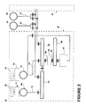
- FIG. 1 is a schematic cross-sectional diagram of a gas turbine engine 10 for an aircraft.
- Engine 10 includes, in downstream serial flow relationship, a fan section 12 including a fan 14, a booster or low pressure (LP) compressor 16, a high pressure (HP) compressor 18, a combustion section 20, a HP turbine 22, and a LP turbine 24.
- a HP shaft or spool 26 drivingly connects HP turbine 22 to HP compressor 18 and a LP shaft or spool 28 drivingly connects LP turbine 24 to LP compressor 16 and fan 14.
- HP turbine 22 includes an HP turbine rotor 30 having turbine blades 32 mounted at a periphery of rotor 30. Blades 32 extend radially outwardly from blade platforms 34 to radially outer blade tips 36.
- FIG. 2 is a schematic block diagram of an electrical power system architecture 40 according to a first embodiment of the invention.
- the system architecture 40 includes multiple engine systems, shown herein as including at least a left engine system 42 and a right engine system 44.
- the left and right engine systems 42, 44 may be substantially identical; therefore, only the left engine system 42 will be described in detail for the sake of brevity.
- the left engine system 42 can include the HP and LP spools 26, 28 of the gas turbine engine 10 shown in FIG. 1 , although the system architecture 40 has application to other engines as well.
- the left engine system 42 shown herein uses mechanical power provided by two spools, the HP spool 26 and the LP spool 28.
- system architecture 40 could also be implemented on an engine having more than two spools, such as a 3-spool engine having an intermediate pressure spool in addition to the HP and LP spools.
- the system architecture 40 can further include an auxiliary power unit (APU) 46 of the aircraft and an external power source (EPS) 48.
- APU auxiliary power unit
- EPS external power source
- the APU 46 and EPS 48 each have a DC output 50, 52, respectively.
- the left engine system 42 includes a first variable frequency starter generator 56, configured to produce variable frequency (VF) AC power from mechanical power supplied by the HP spool 26, and a second variable frequency generator 58 configured to produce variable frequency (VF) AC power from mechanical power supplied by the LP spool 28.
- VF variable frequency
- the HP spool 26 can be operably coupled with the first variable frequency starter generator 56 by an HP drive assembly having an input mechanically coupled to the HP spool 26 and an output mechanically coupled to the first variable frequency starter generator 56.
- One embodiment of the HP drive assembly is an accessory gearbox 64, where the first variable frequency starter generator 56 can be mounted and coupled to the accessory gearbox 64. Within the accessory gearbox 64, power may also be transferred to other engine accessories.
- the first variable frequency starter generator 56 converts mechanical power supplied by the HP spool 26 into electrical power.
- the first variable frequency starter generator 56 can also provide a starting function to the aircraft wherein it functions a motor to start the engine 10.
- the first variable frequency starter generator 56 on the HP side of the left engine system 42 may not necessarily provide a starting function to the aircraft.
- a separate starter motor connected to the accessory gearbox 64 can be provided to perform the starting function for the aircraft.
- the left engine system 42 may include multiple generators drawing mechanical power from the HP spool 26 to produce power in order to provide a measure of redundancy.
- the second variable frequency generator 58 may be identical to the first variable frequency starter generator 56, but for the starting function. In this situation, however, because of the fluctuating speed ranges of the LP spool 28, the LP spool 28 is operably coupled with the first variable frequency starter generator 56 by speed range reduction assembly 74 having an input mechanically coupled to the LP spool 28 and an output mechanically coupled to the second variable frequency generator 58.
- One embodiment of the speed range reduction assembly includes a controller 76 (see Fig. 4 ) that reduces the range of the variable speed input from the LP spool 28 to a range within the tolerances of the second variable frequency generator 58.
- the first variable frequency starter generator 56 converts mechanical power supplied by the HP spool 26 into VF electrical power output.
- second variable frequency generator 58 may use multiple second variable frequency generators 58 drawing mechanical power from the LP spool 28 to produce AC power in order to provide a measure of redundancy.
- second variable frequency generator 58 and speed range reduction assembly 74 are discussed herein, an integrated drive generator which combines the speed range reduction assembly 74 and the second variable frequency generator 58 into a common unit can alternatively be used.
- Power output 68 from the first variable frequency starter generator 56 is supplied to a first electrical AC bus 86.
- power output 78 from the second variable frequency generator 58 is supplied to a second electrical AC bus 94.
- Some AC power 90 is drawn from the first electrical AC bus 86 to an AC/DC converter 84 for converting the AC power output 90 to a DC power output 92 which is fed to an electrical DC bus 98.
- a motor-starter controller 96 can selectively provide power from the electrical DC bus 98 to the first variable frequency starter generator 56 to initiate a starting procedure for the aircraft.
- the motor-starter controller 96 can be integrated with the first variable frequency starter generator 56 for engine starting by connecting the motor-starter controller 96 to first variable frequency starter generator 56 as shown FIG. 2 .
- the first and second electrical buses 86, 94 are configured to supply AC power to one or more loads (not shown) that require a AC power supply.
- the first and second electrical buses 86, 94 can be selectively connected to enable loads to be shared by the HP spool 26 and the LP spool 28.
- HP turbine 22 rotates the HP spool 26 and the LP turbine 24 rotates the LP spool.
- the accessory gearbox 64 is driven by the rotating HP spool 26, and transmits mechanical power from the HP spool 26 to the first variable frequency starter generator 56.
- the first variable frequency starter generator 56 converts mechanical power supplied by the HP spool 26 into electrical power and produces the AC power output 68.
- the speed range reduction assembly 74 is driven by the rotating LP spool 28, and transmits mechanical power from the LP spool 28 to the second variable frequency generator 58.
- the second variable frequency generator 58 converts the mechanical power supplied by the LP spool 28 into electrical power and produces the AC power output 78.
- the power outputs 68, 78 can be respectively provided to the electrical AC buses 86, 94 configured to supply AC power to one or more loads (not shown) that require a AC power supply. Depending on the type of load drawing power, the AC power extracted by the system architecture 40 may undergo further processing before being used by the loads.
- the DC power outputs 50, 52 of the APU 44 and the EPS 48, if converted, can also be provided to the electrical AC buses 86, 94.
- the left and right engine systems 42, 44, APU 46 and EPS 48 can provide DC power to various loads of the aircraft as needed.
- the various DC outputs of the left engine system 42, the right engine system 44, the APU 46, and the EPS 48 are preferably integrated with appropriate switches to provide no break power transfer (NBPT) to the aircraft.
- NBPT no break power transfer
- FIG. 3 is a schematic block diagram of an electrical power system architecture 400 according to a second embodiment of the invention.
- the system architecture 400 includes multiple engine systems, shown herein as including at least a left engine system 420 and a right engine system 440.
- the left and right engine systems 420, 440 may be substantially identical; therefore, only the left engine system 420 will be described in detail for the sake of brevity.
- the left engine system 420 can include the HP and LP spools 26, 28 of the gas turbine engine 10 shown in FIG. 1 , although the system architecture 400 has application to other engines as well.
- the left engine system 420 shown herein uses mechanical power provided by two spools, the HP spool 26 and the LP spool 28.
- system architecture 400 could also be implemented on an engine having more than two spools, such as a 3-spool engine having an intermediate pressure spool in addition to the HP and LP spools.
- the system architecture 40 can further include an auxiliary power unit (APU) 46 of the aircraft and an external power source (EPS) 48. As shown herein, the APU 46 and EPS 48 each have a DC output 50, 52, respectively.
- APU auxiliary power unit
- EPS 48 external power source
- the left engine system 420 includes a first autotransformer unit (ATU) integrated generator 560, shown herein as a first variable frequency starter generator 560, configured to produce variable frequency (VF) AC power from mechanical power supplied by the HP spool 26, and a second ATU integrated generator 580 configured to produce variable frequency (VF) AC power from mechanical power supplied by the LP spool 28.
- ATU autotransformer unit
- the first variable frequency starter generator 560 includes a power generation section 600 and an ATU section 620.
- the ATU section 620 may be integrated with the power generation section 600 by integrating some of the electrical windings necessary for power transformation on the electrical winding of the power generation section 600 which can effectively eliminate winding duplication in the power generation section 600 and the ATU section 620, and can translate into weight and cost savings for the aircraft.
- the HP spool 26 can be operably coupled with the first variable frequency starter generator 560 by an HP drive assembly having an input mechanically coupled to the HP spool 26 and an output mechanically coupled to the power generation section 620.
- One embodiment of the HP drive assembly is an accessory gearbox 640, where the first variable frequency starter generator 560 can be mounted and coupled to the accessory gearbox 640. Within the accessory gearbox 640, power may also be transferred to other engine accessories.
- the power generation section 600 of the first variable frequency starter generator 560 converts mechanical power supplied by the HP spool 26 into electrical power and produces a power supply 660 having three phase outputs.
- the ATU section 620 of the first variable frequency starter generator 560 functions to both transform the three phase outputs of the power supply 660 into a nine phase power output 680 and to step up the voltage of the power supply.
- the first variable frequency starter generator 560 also provides a starting function to the aircraft.
- the first variable frequency starter generator 560 on the HP side of the left engine system 420 may comprise a generator that does not provide a starting function to the aircraft.
- a separate starter motor connected to the accessory gearbox 600 can be provided to perform the starting function for the aircraft.
- the left engine system 420 can include multiple generators drawing mechanical power from the HP spool 26 to produce power in order to provide a measure of redundancy.
- the second variable frequency generator 580 includes a power generation section 700 and an ATU section 720.
- the LP spool 28 can be operably coupled with the second variable frequency generator 580 by an LP drive assembly having an input mechanically coupled to the LP spool 28 and an output mechanically coupled to the power generation section 700.
- One embodiment of the speed range reduction assembly 740 includes a controller that reduces the range of the variable speed input from the LP spool 28 to a range within the tolerances of the second variable frequency generator 58. As shown herein, the speed range reduction assembly 740 can be mechanically coupled to the second variable frequency generator 58 and drives the power generation section 700 at a variable speed different than the input speed.
- the power generation section 700 of the second variable frequency generator 58 converts mechanical power supplied by the LP spool 28 into electrical power and produces a power supply 760 having three phase outputs.
- the ATU section 720 of the second variable frequency generator 58 functions to both transform the three phase outputs of the power supply 760 into a nine phase power output 780 and to step up the voltage of the power supply.
- second variable frequency generator 580 may use multiple second variable frequency generators 58 drawing mechanical power from the LP spool 28 to produce AC power in order to provide a measure of redundancy.
- second variable frequency generator 58 and speed range reduction assembly 740 are discussed herein, an integrated drive generator which combines the speed range reduction assembly 740 and second variable frequency generator 58 into a common unit can alternatively be used.
- the power output 680 from the integrated first variable frequency starter generator 560 is supplied to a first AC/DC converter for converting the AC power output 680 to a DC power output 800.
- the first AC/DC converter can include a first rectifier device 820 and a first filter 840 for converting the AC voltage to DC voltage and for evening out the current flow before being supplied to a first electrical DC bus 860.
- the power output 780 from the second variable frequency generator 580 is supplied to a second AC/DC converter for converting the AC power output 780 to a DC power output 880.
- the second AC/DC converter can include a second rectifier device 900 and a second filter 920 for converting the AC voltage to DC voltage and for evening out the current flow before being supplied to a second electrical DC bus 940.
- a motor-starter controller 960 can selectively provide power from the first electrical bus 860 to the first variable frequency starter generator 560 to initiate a starting procedure for the aircraft.
- the motor-starter controller 960 can be integrated with the first variable frequency starter generator 560 for engine starting by connecting the motor-starter controller 960 to the specific location of the first variable frequency starter generator 560 as shown FIG. 3 .
- the three phase motor-starter controller 960 is connected to the three phase power supply 660 to drive the first variable frequency starter generator 560 as a three phase starter for engine starting.
- the first and second electrical buses 860, 940 are configured to supply DC power to one or more loads (not shown) that require a DC power supply.
- the first and second electrical buses 860, 940 can be selectively connected to enable loads to be shared by the HP spool 26 and the LP spool 28.
- HP turbine 22 rotates the HP spool 26 and the LP turbine 24 rotates the LP spool.
- the accessory gearbox 640 is driven by the rotating HP spool 26, and transmits mechanical power from the HP spool 26 to the first variable frequency starter generator 560.
- the first variable frequency starter generator 560 converts mechanical power supplied by the HP spool 26 into electrical power and produces the DC power output 800.
- the speed range reduction assembly 740 is driven by the rotating LP spool 28, and transmits mechanical power from the LP spool 28 to the second variable frequency generator 580.
- the second variable frequency generator 580 converts the mechanical power supplied by the LP spool 28 into electrical power and produces the DC power output 880.
- the power outputs 800, 880 can be respectively provided to the electrical buses 860, 940 configured to supply DC power to one or more loads (not shown) that require a DC power supply. Depending on the type of load drawing power, the DC power extracted by the system architecture 400 may undergo further processing before being used by the loads.
- the DC power outputs 50, 52 of the APU 44 and the EPS 48 can also be provided to the electrical buses 860, 940.
- the left and right engine systems 42, 44, APU 46 and EPS 48 can provide DC power to various loads of the aircraft as needed.
- the various DC outputs of the left engine system 42, the right engine system 44, the APU 46, and the EPS 48 are integrated with appropriate switches to provide no break power transfer (NBPT) to the aircraft.
- NBPT no break power transfer
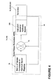
- FIG. 4 is a schematic diagram of the speed range reduction assembly 74, 740.
- the speed range reduction assembly 74, 740 comprises a conventional constant speed drive (CSD) 300 which may be based on a continuously variable transmission or a hydraulic system.
- the CSD 300 may be coupled to the output of the LP spool 28, and integrated with or otherwise coupled to a variable frequency generator 56, 58, 560, 580, and to a controller 32.
- the controller 32 is configured to receive feedback signals 34 from the variable frequency generator 56, 58, 560, 580, and process them with an algorithm of tabular commands 36 to alter the speed of the CSD 300 and the consequent input to the variable frequency generator 56, 58, 560, 580.
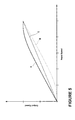
- Fig. 5 illustrates graphically how the output speeds of the CSD 300 are determined by the controller 76.
- Plot A is an empirically determined curve showing an exemplary relationship between input speeds from the LP spool 28 and output speeds from the CSD 300 for a variable frequency generator having high efficiencies at high speeds.
- Plot B is an empirically determined curve showing an exemplary relationship between input speeds from the LP spool 28 and output speeds from the CSD 300 for a variable frequency generator having high efficiencies at low speeds.
- Plot C is an empirically determined curve showing an exemplary purely proportional relationship between input speeds from the LP spool 28 and output speeds from the CSD 300 for a variable frequency generator.
- exemplary speed ranges of LP spool may be 4:1 or 5:1, and they can be reduced to 2:1, which is an exemplary range of the same proximity for a standard VF generator.
- the controller 32 applies the algorithm of the curve correlating to a given generator to reduce the speed range of the output of the CSD 300 from the higher speed range of the input from the LP spool 28.
- the controller 32 continuously receives signals from the input to the CSD 300 and maps the output speed of the CSD 300 to the input speed based on the algorithm.
- the algorithm may be implemented by the controller 76 using tabular commands extracted from the selected curve. Ideally, the mapping can be optimized for the most efficient operation of the generator.
- DC and VF generators that are readily available for extracting power from HP spools can now be operated with LP spools, thereby saving significant cost in separate development and sourcing for generators that are readily available for extracting power from LP spools.
Landscapes
- Engineering & Computer Science (AREA)
- Chemical & Material Sciences (AREA)
- Combustion & Propulsion (AREA)
- Mechanical Engineering (AREA)
- General Engineering & Computer Science (AREA)
- Control Of Eletrric Generators (AREA)
- Connection Of Motors, Electrical Generators, Mechanical Devices, And The Like (AREA)
- Control Of Turbines (AREA)
Applications Claiming Priority (1)
| Application Number | Priority Date | Filing Date | Title |
|---|---|---|---|
| US13/414,065 US20130232941A1 (en) | 2012-03-07 | 2012-03-07 | Apparatus for extracting input power from the low pressure spool of a turbine engine |
Publications (2)
| Publication Number | Publication Date |
|---|---|
| EP2636873A2 true EP2636873A2 (de) | 2013-09-11 |
| EP2636873A3 EP2636873A3 (de) | 2017-12-27 |
Family
ID=47832974
Family Applications (1)
| Application Number | Title | Priority Date | Filing Date |
|---|---|---|---|
| EP13158056.5A Withdrawn EP2636873A3 (de) | 2012-03-07 | 2013-03-06 | Vorrichtung zur Leistungsentnahme von der Niederdruckwelle eines Turbinenmotors |
Country Status (6)
| Country | Link |
|---|---|
| US (1) | US20130232941A1 (de) |
| EP (1) | EP2636873A3 (de) |
| JP (1) | JP6130689B2 (de) |
| CN (1) | CN103306821B (de) |
| BR (1) | BR102013004052A2 (de) |
| CA (1) | CA2808038A1 (de) |
Cited By (4)
| Publication number | Priority date | Publication date | Assignee | Title |
|---|---|---|---|---|
| EP2886387A2 (de) * | 2013-12-23 | 2015-06-24 | Rolls-Royce Corporation | Doppelt redundanter Motor/Generator für einen Motor |
| EP3205850A1 (de) * | 2016-02-12 | 2017-08-16 | Hamilton Sundstrand Corporation | Frequenzvariables gasturbinenmotormotorisierungsgeneratorsystem für starts von motoren mit gebogenem rotor |
| EP3748839A1 (de) * | 2019-06-03 | 2020-12-09 | Hamilton Sundstrand Corporation | Gleichstromgeneratorsystem |
| WO2022208021A1 (fr) | 2021-03-30 | 2022-10-06 | Safran Power Units | Procédé de démarrage piloté d'une turbine a gaz d'un aéronef et systeme correspondant |
Families Citing this family (13)
| Publication number | Priority date | Publication date | Assignee | Title |
|---|---|---|---|---|
| US8723349B2 (en) * | 2011-10-07 | 2014-05-13 | General Electric Company | Apparatus for generating power from a turbine engine |
| US8876650B2 (en) * | 2012-03-30 | 2014-11-04 | Hamilton Sundstrand Corporation | Aircraft accessory drive multiple speed transmission |
| GB2520024B (en) | 2013-11-06 | 2016-02-03 | Ge Aviat Systems Ltd | Electrical power system for an aircraft |
| GB2536876A (en) | 2015-03-23 | 2016-10-05 | Aurelia Turbines Oy | Two-spool gas turbine arrangement |
| US20170233081A1 (en) | 2016-02-13 | 2017-08-17 | Ge Aviation Systems Llc | Method and aircraft for providing bleed air to an environmental control system |
| US10443504B2 (en) * | 2016-10-21 | 2019-10-15 | Ge Aviation Systems Llc | Method for allocating power in an electrical power system architecture |
| US10526975B2 (en) | 2016-11-30 | 2020-01-07 | The Boeing Company | Power extraction system and method for a gas turbine engine of a vehicle |
| US10495186B2 (en) | 2017-01-20 | 2019-12-03 | Hamilton Sundstrand Corporation | Low speed spool generator transmission |
| US10934935B2 (en) * | 2017-01-30 | 2021-03-02 | Ge Aviation Systems Llc | Engine core assistance |
| CA3005542A1 (en) * | 2017-05-23 | 2018-11-23 | Pratt & Whitney Canada Corp. | Engine assembly with a dedicated voltage bus |
| US10718598B2 (en) | 2017-06-23 | 2020-07-21 | Hamilton Sundstrand Corporation | Series hybrid architecture for an unmanned underwater vehicle propulsion system |
| US10689999B2 (en) | 2018-02-22 | 2020-06-23 | Ge Aviation Systems, Llc | Power generation system |
| US11845388B2 (en) | 2021-05-20 | 2023-12-19 | General Electric Company | AC electrical power system for a vehicle |
Family Cites Families (35)
| Publication number | Priority date | Publication date | Assignee | Title |
|---|---|---|---|---|
| GB1460722A (en) * | 1973-01-09 | 1977-01-06 | Lucas Industries Ltd | Electrical generating apparatus |
| US4330743A (en) * | 1980-07-17 | 1982-05-18 | Sundstrand Corporation | Electrical aircraft engine start and generating system |
| US4912921A (en) * | 1988-03-14 | 1990-04-03 | Sundstrand Corporation | Low speed spool emergency power extraction system |
| GB9313905D0 (en) * | 1993-07-06 | 1993-08-25 | Rolls Royce Plc | Shaft power transfer in gas turbine engines |
| US6188203B1 (en) * | 1996-11-01 | 2001-02-13 | Lucas Aerospace Power Equipment Corporation | Ground fault detection circuit |
| JP3457488B2 (ja) * | 1996-11-25 | 2003-10-20 | 株式会社日立製作所 | 自動車の制御装置 |
| JP2972688B2 (ja) * | 1998-01-20 | 1999-11-08 | 株式会社コミュータヘリコプタ先進技術研究所 | 航空機用発電機の定速駆動装置およびトラクション変速装置 |
| JP3440287B2 (ja) * | 1999-12-01 | 2003-08-25 | 川崎重工業株式会社 | 航空機搭載発電機の定速駆動方法および定速駆動装置 |
| JP3593575B2 (ja) * | 2001-02-08 | 2004-11-24 | 川崎重工業株式会社 | 1軸式ガスタービンシステム |
| JP3914999B2 (ja) * | 2001-04-19 | 2007-05-16 | 川崎重工業株式会社 | 変速制御方法および変速制御装置 |
| US6838778B1 (en) * | 2002-05-24 | 2005-01-04 | Hamilton Sundstrand Corporation | Integrated starter generator drive having selective torque converter and constant speed transmission for aircraft having a constant frequency electrical system |
| JP2004116641A (ja) * | 2002-09-26 | 2004-04-15 | Fuji Heavy Ind Ltd | 無段変速機の変速制御装置 |
| JP3927518B2 (ja) * | 2003-06-06 | 2007-06-13 | 川崎重工業株式会社 | 発電装置 |
| US6895741B2 (en) * | 2003-06-23 | 2005-05-24 | Pratt & Whitney Canada Corp. | Differential geared turbine engine with torque modulation capability |
| FR2882096B1 (fr) * | 2005-02-11 | 2012-04-20 | Snecma Moteurs | Turbomoteur a double corps avec des moyens de prise de mouvement sur les rotors basse pression et haute pression, module de prise de mouvement pour le turbomoteur et procede de montage du turbomoteur |
| US7552582B2 (en) * | 2005-06-07 | 2009-06-30 | Honeywell International Inc. | More electric aircraft power transfer systems and methods |
| FR2892456B1 (fr) * | 2005-10-21 | 2008-01-04 | Hispano Suiza Sa | Dispositif d'entrainement de machines accessoires d'un moteur a turbine a gaz |
| US7481062B2 (en) * | 2005-12-30 | 2009-01-27 | Honeywell International Inc. | More electric aircraft starter-generator multi-speed transmission system |
| US20070265761A1 (en) * | 2006-05-11 | 2007-11-15 | Dooley Kevin A | Electric power generation system and method |
| DE102006039608A1 (de) * | 2006-08-24 | 2008-04-10 | Rolls-Royce Deutschland Ltd & Co Kg | Anordnung zur Energieentnahme bei einem Zwei-Wellen-Triebwerk |
| US7750521B2 (en) * | 2006-12-07 | 2010-07-06 | General Electric Company | Double-sided starter/generator for aircrafts |
| US7622817B2 (en) * | 2006-12-13 | 2009-11-24 | General Electric Company | High-speed high-pole count generators |
| US7791235B2 (en) * | 2006-12-22 | 2010-09-07 | General Electric Company | Variable magnetic coupling of rotating machinery |
| US8319481B2 (en) * | 2006-12-26 | 2012-11-27 | Hamilton Sundstrand Corporation | Pole shifting generator |
| US8015828B2 (en) * | 2007-04-03 | 2011-09-13 | General Electric Company | Power take-off system and gas turbine engine assembly including same |
| GB0707319D0 (en) * | 2007-04-17 | 2007-05-23 | Rolls Royce Plc | Apparatus and method of operating a gas turbine engine at start-up |
| US7882691B2 (en) * | 2007-07-05 | 2011-02-08 | Hamilton Sundstrand Corporation | High to low pressure spool summing gearbox for accessory power extraction and electric start |
| US7952220B2 (en) * | 2007-09-21 | 2011-05-31 | Hamilton Sundstrand Corporation | Generator for gas turbine engine having main DC bus accessory AC bus |
| US8427001B2 (en) * | 2008-07-30 | 2013-04-23 | Honeywell International, Inc. | Electrically controlled frequency-based power system architecture for aircraft |
| US8039983B2 (en) * | 2008-12-02 | 2011-10-18 | The Boeing Company | Systems and methods for providing AC power from multiple turbine engine spools |
| US20100162719A1 (en) * | 2008-12-31 | 2010-07-01 | Bowman Ray F | Gas turbine engine |
| JP4700113B2 (ja) * | 2009-02-06 | 2011-06-15 | 川崎重工業株式会社 | 航空機用発電装置 |
| JP5016706B2 (ja) * | 2009-11-04 | 2012-09-05 | 川崎重工業株式会社 | 航空機用始動発電装置 |
| US8561413B2 (en) * | 2010-12-29 | 2013-10-22 | Ge Aviation Systems, Llc | System for powering a vehicle |
| US20130062885A1 (en) * | 2011-09-08 | 2013-03-14 | General Electric Company | Method and apparatus for extracting electrical power from a gas turbine engine |
-
2012
- 2012-03-07 US US13/414,065 patent/US20130232941A1/en not_active Abandoned
-
2013
- 2013-02-21 BR BR102013004052-5A patent/BR102013004052A2/pt not_active IP Right Cessation
- 2013-02-28 CA CA2808038A patent/CA2808038A1/en not_active Abandoned
- 2013-03-04 JP JP2013041372A patent/JP6130689B2/ja active Active
- 2013-03-06 EP EP13158056.5A patent/EP2636873A3/de not_active Withdrawn
- 2013-03-07 CN CN201310072491.6A patent/CN103306821B/zh active Active
Non-Patent Citations (1)
| Title |
|---|
| None |
Cited By (6)
| Publication number | Priority date | Publication date | Assignee | Title |
|---|---|---|---|---|
| EP2886387A2 (de) * | 2013-12-23 | 2015-06-24 | Rolls-Royce Corporation | Doppelt redundanter Motor/Generator für einen Motor |
| EP3205850A1 (de) * | 2016-02-12 | 2017-08-16 | Hamilton Sundstrand Corporation | Frequenzvariables gasturbinenmotormotorisierungsgeneratorsystem für starts von motoren mit gebogenem rotor |
| EP3748839A1 (de) * | 2019-06-03 | 2020-12-09 | Hamilton Sundstrand Corporation | Gleichstromgeneratorsystem |
| US10868483B1 (en) | 2019-06-03 | 2020-12-15 | Hamilton Sundstrand Corporation | DC generator system |
| WO2022208021A1 (fr) | 2021-03-30 | 2022-10-06 | Safran Power Units | Procédé de démarrage piloté d'une turbine a gaz d'un aéronef et systeme correspondant |
| FR3121471A1 (fr) * | 2021-03-30 | 2022-10-07 | Safran Power Units | Procédé de démarrage piloté d’une turbine a gaz d’un aéronef et systeme correspondant |
Also Published As
| Publication number | Publication date |
|---|---|
| CA2808038A1 (en) | 2013-09-07 |
| BR102013004052A2 (pt) | 2014-04-29 |
| US20130232941A1 (en) | 2013-09-12 |
| JP2013185589A (ja) | 2013-09-19 |
| CN103306821B (zh) | 2017-06-13 |
| CN103306821A (zh) | 2013-09-18 |
| JP6130689B2 (ja) | 2017-05-17 |
| EP2636873A3 (de) | 2017-12-27 |
Similar Documents
| Publication | Publication Date | Title |
|---|---|---|
| EP2636873A2 (de) | Vorrichtung zur Leistungsentnahme von der Niederdruckwelle eines Turbinenmotors | |
| US9963095B2 (en) | Electrical power system for an aircraft | |
| EP2568122A2 (de) | Verfahren und Vorrichtung zur Stromerzeugung aus einem Gasturbinenmotor | |
| US11078850B2 (en) | Method for allocating power in an electrical power system architecture | |
| US8561413B2 (en) | System for powering a vehicle | |
| US9257838B2 (en) | Circuit and method for allocating power among generators | |
| US9810155B2 (en) | Method for starting aircraft engines | |
| US8723349B2 (en) | Apparatus for generating power from a turbine engine | |
| US20170107910A1 (en) | Method and apparatus for starting an aircraft engine and operating a power architecture for an aircraft | |
| US9035478B2 (en) | Aircraft engine constant frequency starter/generator |
Legal Events
| Date | Code | Title | Description |
|---|---|---|---|
| PUAI | Public reference made under article 153(3) epc to a published international application that has entered the european phase |
Free format text: ORIGINAL CODE: 0009012 |
|
| AK | Designated contracting states |
Kind code of ref document: A2 Designated state(s): AL AT BE BG CH CY CZ DE DK EE ES FI FR GB GR HR HU IE IS IT LI LT LU LV MC MK MT NL NO PL PT RO RS SE SI SK SM TR |
|
| AX | Request for extension of the european patent |
Extension state: BA ME |
|
| PUAL | Search report despatched |
Free format text: ORIGINAL CODE: 0009013 |
|
| AK | Designated contracting states |
Kind code of ref document: A3 Designated state(s): AL AT BE BG CH CY CZ DE DK EE ES FI FR GB GR HR HU IE IS IT LI LT LU LV MC MK MT NL NO PL PT RO RS SE SI SK SM TR |
|
| AX | Request for extension of the european patent |
Extension state: BA ME |
|
| RIC1 | Information provided on ipc code assigned before grant |
Ipc: F02C 7/36 20060101ALI20171122BHEP Ipc: F02C 7/32 20060101AFI20171122BHEP |
|
| STAA | Information on the status of an ep patent application or granted ep patent |
Free format text: STATUS: THE APPLICATION IS DEEMED TO BE WITHDRAWN |
|
| 18D | Application deemed to be withdrawn |
Effective date: 20180628 |