EP2636892A2 - Installation éolienne et procédé de production d'énergie rotative par le vent - Google Patents
Installation éolienne et procédé de production d'énergie rotative par le vent Download PDFInfo
- Publication number
- EP2636892A2 EP2636892A2 EP13157906.2A EP13157906A EP2636892A2 EP 2636892 A2 EP2636892 A2 EP 2636892A2 EP 13157906 A EP13157906 A EP 13157906A EP 2636892 A2 EP2636892 A2 EP 2636892A2
- Authority
- EP
- European Patent Office
- Prior art keywords
- rotors
- wind
- shaft
- power plant
- rotor
- Prior art date
- Legal status (The legal status is an assumption and is not a legal conclusion. Google has not performed a legal analysis and makes no representation as to the accuracy of the status listed.)
- Withdrawn
Links
- 238000000034 method Methods 0.000 title claims abstract description 22
- 230000000694 effects Effects 0.000 claims description 8
- 239000002689 soil Substances 0.000 claims description 2
- 239000000463 material Substances 0.000 description 7
- 230000000007 visual effect Effects 0.000 description 5
- 239000002131 composite material Substances 0.000 description 4
- 230000007613 environmental effect Effects 0.000 description 4
- 230000002349 favourable effect Effects 0.000 description 3
- 238000004519 manufacturing process Methods 0.000 description 3
- 229910000831 Steel Inorganic materials 0.000 description 2
- 238000010276 construction Methods 0.000 description 2
- 230000001419 dependent effect Effects 0.000 description 2
- 239000000835 fiber Substances 0.000 description 2
- 239000002184 metal Substances 0.000 description 2
- 238000004088 simulation Methods 0.000 description 2
- 239000010959 steel Substances 0.000 description 2
- 229920000049 Carbon (fiber) Polymers 0.000 description 1
- 230000002411 adverse Effects 0.000 description 1
- 230000005540 biological transmission Effects 0.000 description 1
- 230000001914 calming effect Effects 0.000 description 1
- 239000004917 carbon fiber Substances 0.000 description 1
- 230000006735 deficit Effects 0.000 description 1
- 238000003912 environmental pollution Methods 0.000 description 1
- 238000009434 installation Methods 0.000 description 1
- 238000012423 maintenance Methods 0.000 description 1
- VNWKTOKETHGBQD-UHFFFAOYSA-N methane Chemical compound C VNWKTOKETHGBQD-UHFFFAOYSA-N 0.000 description 1
- 230000002123 temporal effect Effects 0.000 description 1
- 239000013598 vector Substances 0.000 description 1
Images


Classifications
-
- F—MECHANICAL ENGINEERING; LIGHTING; HEATING; WEAPONS; BLASTING
- F03—MACHINES OR ENGINES FOR LIQUIDS; WIND, SPRING, OR WEIGHT MOTORS; PRODUCING MECHANICAL POWER OR A REACTIVE PROPULSIVE THRUST, NOT OTHERWISE PROVIDED FOR
- F03D—WIND MOTORS
- F03D3/00—Wind motors with rotation axis substantially perpendicular to the air flow entering the rotor
- F03D3/002—Wind motors with rotation axis substantially perpendicular to the air flow entering the rotor the axis being horizontal
-
- F—MECHANICAL ENGINEERING; LIGHTING; HEATING; WEAPONS; BLASTING
- F03—MACHINES OR ENGINES FOR LIQUIDS; WIND, SPRING, OR WEIGHT MOTORS; PRODUCING MECHANICAL POWER OR A REACTIVE PROPULSIVE THRUST, NOT OTHERWISE PROVIDED FOR
- F03D—WIND MOTORS
- F03D1/00—Wind motors with rotation axis substantially parallel to the air flow entering the rotor
- F03D1/02—Wind motors with rotation axis substantially parallel to the air flow entering the rotor having a plurality of rotors
- F03D1/025—Wind motors with rotation axis substantially parallel to the air flow entering the rotor having a plurality of rotors coaxially arranged
-
- F—MECHANICAL ENGINEERING; LIGHTING; HEATING; WEAPONS; BLASTING
- F03—MACHINES OR ENGINES FOR LIQUIDS; WIND, SPRING, OR WEIGHT MOTORS; PRODUCING MECHANICAL POWER OR A REACTIVE PROPULSIVE THRUST, NOT OTHERWISE PROVIDED FOR
- F03D—WIND MOTORS
- F03D3/00—Wind motors with rotation axis substantially perpendicular to the air flow entering the rotor
- F03D3/06—Rotors
- F03D3/061—Rotors characterised by their aerodynamic shape, e.g. aerofoil profiles
-
- Y—GENERAL TAGGING OF NEW TECHNOLOGICAL DEVELOPMENTS; GENERAL TAGGING OF CROSS-SECTIONAL TECHNOLOGIES SPANNING OVER SEVERAL SECTIONS OF THE IPC; TECHNICAL SUBJECTS COVERED BY FORMER USPC CROSS-REFERENCE ART COLLECTIONS [XRACs] AND DIGESTS
- Y02—TECHNOLOGIES OR APPLICATIONS FOR MITIGATION OR ADAPTATION AGAINST CLIMATE CHANGE
- Y02E—REDUCTION OF GREENHOUSE GAS [GHG] EMISSIONS, RELATED TO ENERGY GENERATION, TRANSMISSION OR DISTRIBUTION
- Y02E10/00—Energy generation through renewable energy sources
- Y02E10/70—Wind energy
- Y02E10/72—Wind turbines with rotation axis in wind direction
-
- Y—GENERAL TAGGING OF NEW TECHNOLOGICAL DEVELOPMENTS; GENERAL TAGGING OF CROSS-SECTIONAL TECHNOLOGIES SPANNING OVER SEVERAL SECTIONS OF THE IPC; TECHNICAL SUBJECTS COVERED BY FORMER USPC CROSS-REFERENCE ART COLLECTIONS [XRACs] AND DIGESTS
- Y02—TECHNOLOGIES OR APPLICATIONS FOR MITIGATION OR ADAPTATION AGAINST CLIMATE CHANGE
- Y02E—REDUCTION OF GREENHOUSE GAS [GHG] EMISSIONS, RELATED TO ENERGY GENERATION, TRANSMISSION OR DISTRIBUTION
- Y02E10/00—Energy generation through renewable energy sources
- Y02E10/70—Wind energy
- Y02E10/74—Wind turbines with rotation axis perpendicular to the wind direction
Definitions
- the invention relates to a wind turbine, comprising a carrier, at least two rotors in the same direction with rotor blades having wings, and at least one shaft through which the rotors are rotatably mounted on both sides of the carrier on the carrier about axes of rotation, wherein the wings in particular have a wing profile.
- the invention relates to a method for generating rotational energy by wind with a wind turbine, wherein on at least one shaft on a carrier on both sides of the carrier mounted rotors with rotor blades having wings are rotated in the same direction by wind.
- the invention relates to a method for utilizing speed differences in a boundary layer when operating a wind turbine with at least two rotors with rotor blades.
- wind turbines are mostly used, which have a horizontal axis of rotation and usually three radially stationary rotor blades. Due to the design with radial rotor blades and rotor diameters of sometimes more than 100 meters, such wind turbines build very high, whereby a landscape image is usually adversely affected.
- designs of rotors have become known in which the rotor blades have an axial extent and in Are substantially in the direction of a mostly vertical axis of rotation, such as a so-called Darrieus rotor or a H-Darrieus rotor. A method in which electrical energy is generated with such a device has the disadvantage of low efficiency.
- the landscape is also affected by such wind turbines with mostly vertical rotor axes. This is also called visual environmental pollution.
- the object of the invention is to provide a wind turbine of the type mentioned, which avoids the disadvantages of the prior art or at least reduced and with the improved efficiency is achieved especially with a low height.
- the first object is achieved in that in a wind turbine of the type mentioned, the axis of rotation of the shaft is deflected from a vertical and the wings are positioned substantially on an imaginary cylinder surface about the axis of rotation.
- a maximum height of the wind turbine which is preferably stationary and designed as high-speed wind turbine with a ⁇ greater than 1, reduced, whereby the landscape is disturbed much less than in known wind turbines with vertical shafts or wind turbines with horizontal waves with radially wings.
- a torque on the shaft is caused by a buoyant force of the wings, preferably with airfoils.
- the force generated by a vane which generates a torque on the shaft, among other things, depending on the current angular position of the wing and usually within an angular range positive, in which a direction of movement of the wing is directed against a wind direction, and over the remaining area negative.
- the output from such a wind turbine power results in addition to the speed of the torque, which is the sum of the transmitted over the individual angle sections of the wings on the shaft moments.
- the moment which is caused during the movement of the wing against the wind direction due to the preferably substantially circumferentially oriented airfoil profile is greater in magnitude than that which is oriented in the opposite direction and is caused by movement of the wing in the wind direction. Therefore, although such a wind turbine can deliver a positive power, which is always reduced by the power that occurs when moving the wing in the wind direction as power loss.
- a wind turbine according to the invention which allows exploiting the boundary layer, has a higher efficiency, since in the boundary layer, the wind speed increases with increasing altitude and thereby the absolute difference between positive power while moving the wing against the wind direction and power loss can be increased. As a result, a negative moment of the wing can be reduced to the shaft or completely eliminated depending on the flow situation.
- a rotational direction of the rotor is preferably selected in operation such that a wing, which passes through different heights due to the deflected from the vertical shaft at a vertex where the wing has reached the maximum height above a ground, rotates counter to the wind direction.
- a moment which is a product of induced buoyancy force and distance to the axis of rotation, is maximum over a whole wing length at a given rotor diameter.
- a moment which is a product of induced buoyancy force and distance to the axis of rotation
- the wings are twisted on the imaginary cylinder to form a helix to produce a uniform torque on the shaft through various angular positions of the rotors.
- the rotors are rotatable about an approximately vertical axis in order to track the rotors in the wind direction when the wind is rotating.
- the wind turbine can always be aligned in the wind direction, so that even with rotating wind efficiency-optimized operation is guaranteed.
- the wind turbine has exactly one carrier which is rotatably mounted or on which the shaft is rotatably mounted with the rotors, wherein the at least one shaft preferably at the top of is preferably mounted as a straight mast running carrier.
- the system can also be protected from storm by being turned out of the wind. This is another advantage over systems with vertical axes of rotation, so-called vertical runners.
- the shaft or the rotors are mounted at a fixed height. Due to an exploitation of the boundary layer, an embodiment with a shaft mounted on a variable height is not required. Wind turbines with a variable height mounted shaft usually have a vertically movable connected to the carrier frame in which the shaft is rotatably mounted, and are therefore very expensive to produce.
- the rotor blades to the shaft toward a substantially closed contour, wherein webs provided and preferably corners at joints rounded between wings and webs are formed.
- the webs which transmit forces and moments from the wings to the shaft, can be made simple and inexpensive to produce, whereas the wings preferably have a wing profile and are more expensive to manufacture. Due to the closed contour of the rotor has no wing tips with tips on which efficiency-reducing vortices, so-called edge vortex losses, would arise.
- the rounded corners of the joints also have the advantage of avoiding edge vortex losses on sharp edges or corners.
- the rotors are H-shaped and preferably the wings are connected via the webs with the shaft.
- H-shaped rotors in particular with wings extending approximately parallel to the axis of rotation, have a particularly good performance, taking into account a predetermined installation space, since the wings can deliver a uniform torque to the shaft over an entire axial extent.
- the H-shaped rotors can also be designed as a closed contour towards the shaft. With such rotors a particularly small space is possible, whereby the impairment of the landscape image is further reduced.
- a wind vane for tracking the rotors in the wind direction. This allows tracking of the rotors in the wind direction in a particularly simple and automated manner.
- the axes of rotation of the rotors are arranged at an angle of less than 45 °, in particular less than 20 °, preferably less than 5 °, to a horizontal. Such an arrangement allows a maximum utilization of the boundary layer while minimizing the overall height.
- the rotors have a ratio of one rotor diameter to one rotor length between 0.5 and 2, in particular between 0.8 and 1.2, preferably about 1. This allows on the one hand a low deflection of the rotors and on the other hand an optimized material stress of the shaft, which preferably consists of steel.
- a ratio of a ground clearance of the shaft to the rotor diameter is less than 5, preferably less than 3, in particular about 2.
- a bottom effect can also be used which, due to the relative bottom proximity of the rotor, results in a more uniform flow and thus a lower material stress.
- a ratio of ground clearance to rotor diameter has proven to be particularly favorable in terms of visual environmental impact.
- the ground clearance of the shaft is the smallest distance of the shaft to the ground on which the wind turbine is mounted.
- the shaft is preferably mounted on the mast top to minimize the space of the wind turbine. It is advantageous if at the top of the mast, a generator is arranged, which is connected to the shaft and in which the rotational energy of the rotors is converted into electrical energy.
- a control loop is provided, with which the rotors can be aligned in the wind direction.
- a tracking in the wind direction can be particularly simple and highly accurate even with weak winds when the wind direction is measured in order to operate the wind turbine always in an optimal range.
- the rotors each have three blades offset by about 120 °. This has proven to be particularly effective, on the one hand to achieve a uniform torque on the shaft and on the other minimal material costs in a production.
- the second object is achieved in that in a method of the type mentioned, the rotors are rotated about a deflected from a vertical axis of rotation of the shaft with substantially on an imaginary cylinder surface arranged around the axis of rotation wings.
- electrical energy can be obtained by wind at low height.
- the fact that the wings are positioned on an imaginary cylinder surface has the particular advantage that the moment transmitted from a wing to the shaft has a maximum value over the entire wing length the distance between the wing and the shaft is always the same. As a result, a maximum of electrical power is generated at low height.
- the vertical axis of rotation deflected allows a particularly low height, especially in comparison with conventional vertical axes Darrieus rotors, whereby the visual environmental impact is reduced.
- the rotors are operated at such a distance from the ground that an efficiency-increasing soil effect is utilized.
- the bottom effect results from a calming flow near the bottom, which causes reduced turbulence and thus a more even and thus reduced material stress as well as an improved efficiency. At the same time, this minimizes power dissipation caused by a counter moment caused by the vanes when moving in the wind direction, thereby improving the efficiency.
- the rotors are operated in a boundary layer within which a velocity is greater in an upper region than in a lower region. As a result, the power loss caused by the movement of the blades in the wind direction, further reduced.
- the rotors are preferably rotated in such a way that they perform at a vertex movement approximately opposite to the wind direction, wherein the vertex designates the highest point that passes through a wing during a rotation about the axis of rotation.
- the rotors are tracked about a vertical axis of a wind direction.
- the method can be used to generate energy even in changing wind direction.
- the third object is achieved in that in a method for exploiting differences in speed in a boundary layer when operating a wind turbine with at least two rotors with rotor blades, the rotor blades are employed, spaced and positioned such that during rotation of the rotor, a counter-torque of the rotor blades due to different flow rates is reduced in the boundary layer over a rotor circumference.
- the rotor blades bring during a revolution about the axis of rotation only over a limited Angle range a positive moment on the shaft, while in the remaining angular range, a moment contribution of the wings on the shaft negative.
- An output power of the wind turbine is thus in addition to a rotational speed of the rotor of a sum of the transmitted from the rotor blades to the shaft moments over a whole revolution dependent, wherein the proportion of negative moments can be referred to as a counter-torque, which causes a power loss.
- This counter-moment occurs in an area in which the movement of the wing is at least partially directed in the wind direction.
- the wind turbine When operating the wind turbine in the boundary layer, the wind turbine is preferably positioned such that the shaft is arranged approximately parallel to the ground and the rotor rotates such that the wings at the apex have approximately a speed which is directed against the wind direction.
- the wings At a lowermost point, the wings have a direction of movement corresponding to the wind direction, thereby minimizing the counter-momentum generated in this area due to the low wind speed in a lower portion of the boundary layer.
- the rotors are tracked in the wind direction in order to continuously generate electrical energy even with a rotating wind.
- Fig. 1 shows a schematic representation of a wind turbine 1 for generating electrical energy by wind, wherein a shaft 7 is mounted directly on a support 2, are attached to the two rotors 3 on both sides of the carrier 2, preferably immovable in a vertical direction.
- each has Rotor 3 three rotor blades 4, the webs 6 and 5 wings include, wherein the wings 5 of the rotor blades 4 have a wing profile and are connected via the webs 6 with the rotatably mounted on a support tip shaft 7.
- the shaft 7 is arranged horizontally, with even slight deviations from a horizontal of up to 45 ° are possible.
- a rotation direction 9 of the rotors 3 is set in the embodiment in such a way that the vanes 5, which pass through different ground spacings during one rotation about an axis of rotation 13 common to both rotors 3, at a vertex at which a distance of the vanes 5 to a floor maximum is, have a speed which is directed exactly opposite to a wind direction 8.
- differences in speed which predominate in a boundary layer close to the ground and lead to an increase in speed with increasing ground clearance, can be exploited particularly favorably.
- An efficiency is increased by the fact that a counter-torque that occurs when rotating the blades 5 in the wind direction 8, as inevitably takes place in a lower portion of the rotors 3 during a revolution, while minimizing power loss is minimized.
- this counter-torque is also dependent on an angle of attack of an airfoil profile of the vanes 5, which is preferably set fixedly and not changed during one revolution in order to keep maintenance intensity low.
- An employment of the wings 5 and a distance of the wings 5 to each other and a specific configuration of the geometric parameters can preferably be optimized depending on the field of application of the wind turbine 1 by means of numerical simulations, so that the counter-torque is minimized adapted to local conditions.
- the wind turbine 1 according to the invention is designed such that the rotors 3 of the wind direction 8 are trackable.
- the shaft 7 is rotatably mounted about a vertical axis, wherein preferably, the mast tip is rotated about a remaining part of the carrier 2.
- the entire carrier 2, on which the shaft 7 is arranged is mounted so as to be rotatable about a vertical axis about a bottom.
- the shaft 7 is connected to an electrical generator, which is preferably also mounted on the tip of the carrier 2, although also a derivative of the mechanical energy, for example via a transmission, to a arranged on a foot of the carrier 2 generator is possible.
- the shaft 7 is made of a metal, preferably a steel, and the Wing 5 and the webs 6 made of a fiber composite material, preferably a carbon fiber composite material is formed.
- the carrier 2 can be formed both from a metal and from a high-strength composite material which is suitable for absorbing the occurring, in particular changing, forces and moments.
- the rotor blades 4 are formed such that the wings 5 are positioned approximately on a cylinder surface about the rotor axis and movable during movement on this cylinder surface to produce a consistently high torque over an entire length of the wings 5 and to the shaft 7 to be transmitted.
- the wings 5 are not designed as shown approximately parallel to the axis of rotation 13, but twisted into a helix to deliver the most uniform possible torque to the shaft 7 and thus to increase a mechanical life of the individual components. It is advantageous that the rotor blades 4 as shown with the shaft 7 include a closed contour, so that no open ends are present with tips on which could form vortices, which would reduce the efficiency. For the same reason, the edges are rounded at the joints between the wings 5 and the webs 6, resulting in a particularly high efficiency of the wind turbine 1.
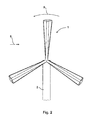
- Fig. 2 shows a wind turbine 1 according to the invention in side view, the running three rotor blades 4 per rotor 3 are particularly clearly visible.
- the three rotor blades 4 are uniformly spaced apart and arranged offset by approximately 120 ° to each other.
- an embodiment of the wind turbine 1 with two rotors 3, each having three rotor blades 4 has proven itself, wherein an embodiment with only two or more than three rotor blades 4 can also be provided.
- the rotors 3 are preferably mounted on both sides of the carrier 2 in order to ensure a symmetrical loading of the carrier 2 and to be able to carry out a tracking of the rotors 3 in the wind direction 8 about a vertical axis passing through the vertical carrier 2.
- the rotors 3 are mounted on a common shaft 7 on the support 2 about a common axis of rotation 13, but it is also the separate storage on individual shafts 7 and rotatable about separate axes of rotation possible, for example, in case of failure of a rotor 3 is still a limited To guarantee plant availability.
- Each rotor 3 of the illustrated wind turbine 1 has an axial extent of about 5 meters and a diameter of also 5 meters.
- a ratio of one rotor length to one rotor diameter is between 0.5 and 2.
- the shaft 7 of the illustrated embodiment is positioned at a height of about 10 meters above the ground so that a height can be minimized, thereby minimizing visual environmental impact as compared to prior art wind turbines.
- the effect according to the invention is also achieved with deviating parameters from the dimensions described above.
- the system can also be designed with a height of much more than 15 meters.
- a rotor diameter of less than 15 meters has proven particularly useful.
- the rotor diameter is the diameter of the imaginary cylinder on which the wings 5 are arranged; as the rotor length, the length of the wings 5 is to be regarded on the imaginary cylinder per rotor 3.
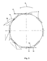
- Fig. 3 shows demonstratively speed relationships on the wings 5 at various angular positions of a conventional rotor 3, for example a Darrieus rotor, which has a vertical axis as usual in wind turbines of the prior art.
- a relative velocity 10 of the vanes 5 having an airfoil profile relative to the flow results from a vectorial addition of a flow velocity 12 resulting from a rotation of the vanes 5 about the axis of rotation 13 and a wind velocity 11.
- This relative velocity 10 becomes maximum at a point where a wing velocity is directed against the wind direction 8.
- the negative moment caused in the lower area becomes and thus minimizes the power loss and thus increases the overall efficiency of the wind turbine 1.
- the direction of rotation 9 is preferably selected such that the vanes 5 have a vane velocity at the apex which is directed approximately counter to the wind speed 11 and at a point at which the vanes 5, the co-rotating rotors 3, have the smallest distance to the ground.
- the wing speed is directed in the direction of the wind speed 11, for which reason the flow speed 12 is opposite due to the rotation of the wind speed 11 and the relative speed 10 is minimized.
- Fig. 4 shows a further embodiment of a wind turbine 1 according to the invention with also arranged substantially on an imaginary cylinder surface wings 5 of rotor blades 4.
- two, both sides of the carrier 2 arranged rotors 3 are provided with three rotor blades 4, wherein the rotor blades 4 to a Helix are arranged twisted.
- This embodiment has the particular advantage that a torque acting on the shaft 7 is applied uniformly and temporal variations are almost eliminated.
- a twist angle is preferably optimized again in numerical simulations and adapted to the particular application. Has proven particularly useful a twist angle, which, as can be seen in the embodiment, approximately one half of an angular distance of the individual rotor blades 4 corresponds.
- a particularly uniform torque curve and a low material stress is achieved.
- a particularly high material utilization is achieved in that the common shaft 7 of both rotors 3 has a shorter axial extent than the rotors 3 and is attached only on one side of each rotor 3.
- the preferred light and in particular of a high-strength Fiber composite running wings 5 have a self-supporting effect. This makes it possible to further reduce a production cost of the wind turbine 1.
Landscapes
- Engineering & Computer Science (AREA)
- Life Sciences & Earth Sciences (AREA)
- Sustainable Development (AREA)
- Sustainable Energy (AREA)
- Chemical & Material Sciences (AREA)
- Combustion & Propulsion (AREA)
- Mechanical Engineering (AREA)
- General Engineering & Computer Science (AREA)
- Physics & Mathematics (AREA)
- Fluid Mechanics (AREA)
- Wind Motors (AREA)
Applications Claiming Priority (1)
| Application Number | Priority Date | Filing Date | Title |
|---|---|---|---|
| ATA50055/2012A AT512564A1 (de) | 2012-03-05 | 2012-03-05 | Windkraftanlage und Verfahren zum Erzeugen von rotatorischer Energie durch Wind |
Publications (2)
| Publication Number | Publication Date |
|---|---|
| EP2636892A2 true EP2636892A2 (fr) | 2013-09-11 |
| EP2636892A3 EP2636892A3 (fr) | 2014-03-12 |
Family
ID=49111627
Family Applications (1)
| Application Number | Title | Priority Date | Filing Date |
|---|---|---|---|
| EP13157906.2A Withdrawn EP2636892A3 (fr) | 2012-03-05 | 2013-03-05 | Installation éolienne et procédé de production d'énergie rotative par le vent |
Country Status (2)
| Country | Link |
|---|---|
| EP (1) | EP2636892A3 (fr) |
| AT (1) | AT512564A1 (fr) |
Cited By (3)
| Publication number | Priority date | Publication date | Assignee | Title |
|---|---|---|---|---|
| EP3112674A1 (fr) * | 2015-07-02 | 2017-01-04 | Rotation Consultancy & Science Publications | Système d'éolienne pour générer de l'énergie électrique sur un navire et navire comprenant un tel système |
| US20220120258A1 (en) * | 2020-10-20 | 2022-04-21 | Forcegenie, Llc | Wind, wave, and water power generation system |
| US20240426276A1 (en) * | 2020-10-20 | 2024-12-26 | Forcegenie, Llc | Wind, wave, and water power generation system |
Citations (1)
| Publication number | Priority date | Publication date | Assignee | Title |
|---|---|---|---|---|
| EP2098722A2 (fr) * | 2008-03-03 | 2009-09-09 | Remmer Dipl.-Ing. Briese | Éolienne |
Family Cites Families (10)
| Publication number | Priority date | Publication date | Assignee | Title |
|---|---|---|---|---|
| US3867067A (en) * | 1973-09-06 | 1975-02-18 | Edwin K Hillman | Wind powered motive apparatus |
| SU1173059A1 (ru) * | 1983-07-29 | 1985-08-15 | Kuzin Anatolij A | Ветродвигатель |
| JP2000265936A (ja) * | 1999-03-17 | 2000-09-26 | Akaho Yoshio | ダリウス形水車および潮流発電装置 |
| JP2003328923A (ja) * | 2002-05-13 | 2003-11-19 | Mitsubishi Heavy Ind Ltd | 水平軸型風車発電装置 |
| US20080304963A1 (en) * | 2007-06-08 | 2008-12-11 | Awni Riadh M M | Tilting flaps to drive wind power generators or gearboxes |
| US8246302B2 (en) * | 2007-09-06 | 2012-08-21 | Hamilton Sundstrand Corporation | Teeter-restraint device for wind turbines |
| WO2009149016A2 (fr) * | 2008-06-01 | 2009-12-10 | Broadstar Developments Lp | Générateur électrique éolien et ses applications |
| US8376711B2 (en) * | 2008-10-28 | 2013-02-19 | Aeronet Inc. | Dual rotor wind turbine |
| GB2470501B (en) * | 2009-05-19 | 2011-03-30 | Fu-Chang Liao | Wind-powered electricity generator |
| WO2011162498A2 (fr) * | 2010-06-21 | 2011-12-29 | Won In Ho | Générateur d'électricité à deux colonnes mû par le vent pour flux d'air turbulent |
-
2012
- 2012-03-05 AT ATA50055/2012A patent/AT512564A1/de not_active Application Discontinuation
-
2013
- 2013-03-05 EP EP13157906.2A patent/EP2636892A3/fr not_active Withdrawn
Patent Citations (1)
| Publication number | Priority date | Publication date | Assignee | Title |
|---|---|---|---|---|
| EP2098722A2 (fr) * | 2008-03-03 | 2009-09-09 | Remmer Dipl.-Ing. Briese | Éolienne |
Cited By (4)
| Publication number | Priority date | Publication date | Assignee | Title |
|---|---|---|---|---|
| EP3112674A1 (fr) * | 2015-07-02 | 2017-01-04 | Rotation Consultancy & Science Publications | Système d'éolienne pour générer de l'énergie électrique sur un navire et navire comprenant un tel système |
| US20220120258A1 (en) * | 2020-10-20 | 2022-04-21 | Forcegenie, Llc | Wind, wave, and water power generation system |
| US11661921B2 (en) * | 2020-10-20 | 2023-05-30 | Forcegenie, Llc | Wind, wave, and water power generation system |
| US20240426276A1 (en) * | 2020-10-20 | 2024-12-26 | Forcegenie, Llc | Wind, wave, and water power generation system |
Also Published As
| Publication number | Publication date |
|---|---|
| EP2636892A3 (fr) | 2014-03-12 |
| AT512564A1 (de) | 2013-09-15 |
Similar Documents
| Publication | Publication Date | Title |
|---|---|---|
| EP2655874B1 (fr) | Rotor d'éolienne éolienne et procédé de production énergétique | |
| DE69404179T2 (de) | Windkraftmaschine | |
| AT512326B1 (de) | Strömungsmaschine | |
| DE102009038076A1 (de) | Rotorelement zur Umströmung durch ein Fluid und Rotor | |
| DE2535138A1 (de) | Vorrichtung zur ausnutzung der windenergie | |
| WO2005100785A1 (fr) | Roue eolienne commandee par un flux, a orientation des pales dependante du vent | |
| EP3677771A1 (fr) | Éolienne verticale | |
| EP3963204B1 (fr) | Rotor pour une éolienne et éolienne | |
| DE112017004377B4 (de) | Windturbinenanlage | |
| EP2636892A2 (fr) | Installation éolienne et procédé de production d'énergie rotative par le vent | |
| DE102012107250B4 (de) | Rotor einer vertikalachsigen Windkraftanlage | |
| EP1387954B1 (fr) | Eolienne a axe vertical | |
| EP4112924A1 (fr) | Rotor pour une éolienne et procédé de fonctionnement d'une éolienne | |
| AT525831B1 (de) | Vertikale Windturbine mit integrierten Fliehkraftklappen | |
| DE10340112A1 (de) | Windkraftanlage | |
| EP4361435A1 (fr) | Eolienne a axe vertical | |
| DE102009008805A1 (de) | Windkraftanlage | |
| DE202008010290U1 (de) | Windkraft nach dem Darrieus-Prinzip | |
| DE202020000307U1 (de) | Vertikale Windenergieanlage | |
| DE102015011260A1 (de) | Windkraftanlage mit mehr als einem Flügel je Flügelflansch des Rotors | |
| DE10214441A1 (de) | Windkraftanlage mit entgegengesetzt rotierenden Laufrädern | |
| EP1507973B1 (fr) | Turbine eolienne a gaine | |
| DE202013102147U1 (de) | Windrad | |
| DE202022105938U1 (de) | Windkraftanlage | |
| DE202022107010U1 (de) | Gegenläufige Windturbine und Windkraftanlage mit einer gegenläufigen Windturbine |
Legal Events
| Date | Code | Title | Description |
|---|---|---|---|
| PUAI | Public reference made under article 153(3) epc to a published international application that has entered the european phase |
Free format text: ORIGINAL CODE: 0009012 |
|
| AK | Designated contracting states |
Kind code of ref document: A2 Designated state(s): AL AT BE BG CH CY CZ DE DK EE ES FI FR GB GR HR HU IE IS IT LI LT LU LV MC MK MT NL NO PL PT RO RS SE SI SK SM TR |
|
| AX | Request for extension of the european patent |
Extension state: BA ME |
|
| PUAL | Search report despatched |
Free format text: ORIGINAL CODE: 0009013 |
|
| AK | Designated contracting states |
Kind code of ref document: A3 Designated state(s): AL AT BE BG CH CY CZ DE DK EE ES FI FR GB GR HR HU IE IS IT LI LT LU LV MC MK MT NL NO PL PT RO RS SE SI SK SM TR |
|
| AX | Request for extension of the european patent |
Extension state: BA ME |
|
| RIC1 | Information provided on ipc code assigned before grant |
Ipc: F03D 3/02 20060101AFI20140205BHEP Ipc: F03D 3/00 20060101ALI20140205BHEP Ipc: F03D 3/06 20060101ALI20140205BHEP |
|
| 17P | Request for examination filed |
Effective date: 20140910 |
|
| RBV | Designated contracting states (corrected) |
Designated state(s): AL AT BE BG CH CY CZ DE DK EE ES FI FR GB GR HR HU IE IS IT LI LT LU LV MC MK MT NL NO PL PT RO RS SE SI SK SM TR |
|
| 17Q | First examination report despatched |
Effective date: 20160229 |
|
| STAA | Information on the status of an ep patent application or granted ep patent |
Free format text: STATUS: THE APPLICATION IS DEEMED TO BE WITHDRAWN |
|
| 18D | Application deemed to be withdrawn |
Effective date: 20160712 |