EP2636984A2 - Stutzenschaft - Google Patents
Stutzenschaft Download PDFInfo
- Publication number
- EP2636984A2 EP2636984A2 EP13155886.8A EP13155886A EP2636984A2 EP 2636984 A2 EP2636984 A2 EP 2636984A2 EP 13155886 A EP13155886 A EP 13155886A EP 2636984 A2 EP2636984 A2 EP 2636984A2
- Authority
- EP
- European Patent Office
- Prior art keywords
- shaft
- stutzenschaft
- front part
- shank
- schafthinterteil
- Prior art date
- Legal status (The legal status is an assumption and is not a legal conclusion. Google has not performed a legal analysis and makes no representation as to the accuracy of the status listed.)
- Granted
Links
Images

Classifications
-
- F—MECHANICAL ENGINEERING; LIGHTING; HEATING; WEAPONS; BLASTING
- F41—WEAPONS
- F41C—SMALLARMS, e.g. PISTOLS, RIFLES; ACCESSORIES THEREFOR
- F41C23/00—Butts; Butt plates; Stocks
- F41C23/18—Butts; Butt plates; Stocks characterised by the material used
-
- F—MECHANICAL ENGINEERING; LIGHTING; HEATING; WEAPONS; BLASTING
- F41—WEAPONS
- F41C—SMALLARMS, e.g. PISTOLS, RIFLES; ACCESSORIES THEREFOR
- F41C23/00—Butts; Butt plates; Stocks
-
- F—MECHANICAL ENGINEERING; LIGHTING; HEATING; WEAPONS; BLASTING
- F41—WEAPONS
- F41C—SMALLARMS, e.g. PISTOLS, RIFLES; ACCESSORIES THEREFOR
- F41C23/00—Butts; Butt plates; Stocks
- F41C23/16—Forestocks; Handgrips; Hand guards
-
- F—MECHANICAL ENGINEERING; LIGHTING; HEATING; WEAPONS; BLASTING
- F41—WEAPONS
- F41C—SMALLARMS, e.g. PISTOLS, RIFLES; ACCESSORIES THEREFOR
- F41C23/00—Butts; Butt plates; Stocks
- F41C23/20—Butts; Butt plates; Mountings therefor
Definitions
- the invention relates to a nozzle stem according to the preamble of claim 1.
- Stub shafts for repeating rifles are often produced as so-called whole shafts from one part.
- Stutzen2020fte with a rear part and a reaching to the muzzle Stutzenvorderschaft.
- Stutzenvorderschaft is usually attached to the barrel. The field of application of such Stutzen2020fte is limited.
- the object of the invention is to provide a nozzle shaft of the type mentioned, which is more versatile.
- the shaft front part is detachably connected to the buttock.
- the spigot shaft consisting of several parts can therefore be assembled and disassembled as a whole unit, whereby the assembly or a possibly required disassembly is considerably simplified.
- Another significant advantage of the nozzle stem according to the invention is that it can be used more versatile.
- the upper part of the shaft for example, can be easily removed and replaced by a short forearm end, so that a partial or half shaft is created which ends, for example, after half the run length and can therefore also be used as a shaft for "half-handled" repeating rifles.
- the buttock piece can be used universally, since, for example, or tripod receptacles or other attachments can be placed on the buttocker instead of a nozzle front part or a Vorderschaftab gleiches.
- the concept according to the invention thus offers a modular construction which enables a shaft to be adapted to the different requirements in a simple and cost-effective manner.
- the shaft front part and the buttock part are connected to one another via a plug connection, wherein the plug connection can also be secured via additional fastening elements.
- the plug connection may preferably comprise an insertion part arranged on the shaft front part and a slot-shaped receptacle on the shaft rear part corresponding to the insertion part.
- the slot-shaped receptacle may be formed on the Schafthinterteil by an upper support surface and lateral webs on the inside of two side cheeks of Schafthinterteils.
- the plug-in connection may comprise a positioning device, which may be e.g. a arranged on the shaft front part positioning for positive engagement in a corresponding receptacle on the buttock part contains.
- a positioning device which may be e.g. a arranged on the shaft front part positioning for positive engagement in a corresponding receptacle on the buttock part contains.
- the shaft front may e.g. be formed as a one-piece nozzle Vorderschaft. But on the Stutzenvorderschaft but can also be attached a removable Vorderschaftab gleich.
- a good and shapely connection of the shaft parts can be achieved by providing curved contact surfaces at the front end of the buttock part for fitting corresponding contact surfaces of the front part of the shaft.
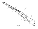
- FIG. 1 a socket shaft 1 of a repeating rifle assembled from a shaft front part 2 and a shaft rear part 3 is shown.
- the shaft front part 2 is designed as a nozzle front shaft and designed such that it extends to the mouth of a run, not shown.
- the Schafthinterteil 3 is designed in the form of a partial or half-shaft with a pistol grip 4 and provided behind the pistol grip thumb hole 5.
- the Schafthinterteil 3 has a cheekpiece 6 with an insert 7. Also on the pistol grip 4 and in the front region of the Schafthinterteils 3 handle inserts 8 and 9 are provided.
- the Schafthinterteil 1 need not be designed as a perforated shaft, but may also have a classic shaft shape and be designed with or without cheekpiece
- the shank front part 2 is detachably connected to the buttock piece 3 via a plug connection, which will be explained in more detail below.
- the shank front part 2 which is in the form of an angled stem, can thus be easily detached from the buttock 3.
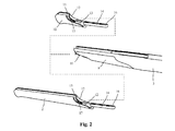
- the front shaft part 2 can on the Schafthinterteil 3 a in FIG. 2 shown Vorderschaftab gleich 10 are placed so that an in FIG. 3 shown Opera- or half-shaft arises, for example, ends after half the run length and therefore can be used as a shank for "half-busted" repeating rifles.
- the forearm end 10 other front end parts, such as, for example, receptacles for a tripod or other attachments, can also be plugged onto the buttock piece 3.
- the shaft is versatile
- FIG. 2 it can be seen that at the front end of the Schafthinterteils 3 curved contact surfaces 11 are provided to rest corresponding thereto connecting surfaces 12 and 13 on the shaft front part 2 and Vorderschaftab gleich 10. At the shaft front part 2 and at the forend 10 are projecting, ridge-shaped Inserted 14 for insertion into the Schafthinterteil 3 formed. In addition, an upwardly projecting positioning element 15 is arranged on the front shaft part 2 and on the forearm end 10 for the positive connection with the buttock part 3. In the free end of the male part 14 is a countersunk bore screw receiving 16 and in the vicinity of the positioning member 15 is also a threaded hole 17 for in FIG. 4 shown fastening screws arranged as fastening elements 18.
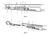
- the Schafthinterteils 3 Like from the FIGS. 4 and 5 It can be seen that at the front end of the Schafthinterteils 3 a receptacle 19 for the positive engagement of the positioning member 15 and a countersunk bore designed as a screw receptacle 20 for the front mounting screw. In Schafthinterteil 3 also has a threaded bore 21 is arranged for the rear mounting screw. In addition, the Schafthinterteil 3 has a slot-shaped receptacle 22 for the web-shaped insertion part 14. The slot-shaped receptacle 22 is bounded by an upper support surface 23 and a plurality of spaced apart lateral webs 24. The lateral webs 24 are according to FIG. 3 formed on the inside of two side cheeks 25 and 26 in the front region of the Schafthinterteils 3. At the webs 24 are in FIG. 5 recognizable depressions 27 which have the height of the web-shaped insertion part 14 and laterally delimit the slot-shaped receptacle 22 for the positive reception of the insertion part 14.
- the positioning element 15 provided on the shaft front part 2 and on the forend 10 is designed as an upwardly projecting wedge-shaped nose.
- the associated receptacle 19 on the buttock part 3 is designed as a wedge-shaped depression with a contour adapted to the nose for the positive engagement of the wedge-shaped nose.
- the shaft front part can simply be plugged together with the buttock part and exactly joined together via the positioning element 15. become. By the additional fasteners 18, the connection is secured.
- the shank front part 2 and the buttock piece 3 can be manufactured in a cost-effective and robust plastic version, e.g. be produced by injection molding.
- the insert 7 and the handle inserts 8 and 9 may consist of a rubber-like thermoplastic elastomer.
- the deposits may also consist of another suitable plastic, leather or other comparable materials.
Landscapes
- Engineering & Computer Science (AREA)
- General Engineering & Computer Science (AREA)
- Toys (AREA)
- Housing For Livestock And Birds (AREA)
- Fishing Rods (AREA)
- Telescopes (AREA)
Abstract
Description
- Die Erfindung betrifft einen Stutzenschaft nach dem Oberbegriff des Anspruchs 1.
- Stutzenschäfte für Repetiergewehre werden vielfach als sogenannte Ganzschäfte aus einem Teil hergestellt. Es sind aber auch bereits mehrteilige Stutzenschäfte mit einem Hinterteil und einem bis zur Laufmündung reichenden Stutzenvorderschaft bekannt. Bei diesen bekannten Stutzenschäften ist der Stutzenvorderschaft jedoch in der Regel am Lauf befestigt. Der Einsatzbereich solcher Stutzenschäfte ist jedoch beschränkt.
- Aufgabe der Erfindung ist es, einen Stutzenschaft der eingangs genannten Art zu schaffen, der vielseitiger einsetzbar ist.
- Diese Aufgabe wird durch einen Stutzenschaft mit den Merkmalen des Anspruchs 1 gelöst. Zweckmäßige Weiterbildungen und vorteilhafte Ausführungsformen der Erfindung sind Gegenstand der Unteransprüche.
- Bei dem erfindungsgemäßen Stutzenschaft ist der Schaftvorderteil abnehmbar mit dem Schafthinterteil verbunden. Der aus mehreren Teilen bestehende Stutzenschaft kann daher als gesamte Einheit montiert und demontiert werden, wodurch der Zusammenbau bzw. eine evtl. erforderliche Demontage erheblich vereinfacht wird. Ein weiterer wesentlicher Vorteil des erfindungsgemäßen Stutzenschafts besteht darin, dass er vielseitiger eingesetzt werden kann. Der z.B. als Stutzenvorderschaft ausgeführte Schaftvorderteil kann einfach abgenommen und durch einen kurzen Vorderschaftabschluss ersetzt werden, so dass ein Teil- oder Halbschaft entsteht, der z.B. nach der halben Lauflänge endet und daher auch als Schaft für "halbgeschäftete" Repetiergewehre eingesetzt werden kann. Das Schafthinterteil ist universell einsetzbar, da anstelle eines Stutzenvorderteils oder eines Vorderschaftabschlusses z.B. auch oder Dreibeinaufnahmen oder andere Anbauteile auf das Schafthinterteil aufgesetzt werden können. Das erfindungsgemäße Konzept bietet somit eine Modulbauweise, die auf einfache und kostengünstige Weise die Anpassung eines Schafts an die unterschiedlichen Anforderungen ermöglicht.
- In einer besonders vorteilhaften Ausführungsform sind der Schaftvorderteil und der Schafthinterteil über eine Steckverbindung miteinander verbunden, wobei die Steckverbindung auch noch über zusätzliche Befestigungselemente gesichert sein kann. Dadurch ist eine besonders schnelle und dennoch sichere Verbindung der Schaftteile erreichbar.
- Die Steckverbindung kann vorzugsweise ein am Schaftvorderteil angeordnetes Einsteckteil und eine zu dem Einsteckteil korrespondierende schlitzförmige Aufnahme am Schafthinterteil umfassen. In einer vorteilhaften Ausgestaltung kann die schlitzförmige Aufnahme am Schafthinterteil durch eine obere Auflagefläche und seitliche Stege an der Innenseite zweier Seitenwangen des Schafthinterteils gebildet sein.
- In einer weiteren vorteilhaften Ausführung kann die Steckverbindung eine Positioniereinrichtung umfassen, die z.B. ein am Schaftvorderteil angeordnetes Positionierelement zum formschlüssigen Eingriff in eine dazu korrespondierende Aufnahme am Schafthinterteil enthält. Dadurch kann eine genaue Positionierung der beiden Schaftteile mit einer exakten Vorgabe der Position in Längsrichtung erreicht werden.
- Der Schaftvorderteil kann z.B. als einteiliger Stutzenvorderschaft ausgebildet sein. Auch auf dem Stutzenvorderschaft kann aber auch ein abnehmbarer Vorderschaftabschluss angebracht sein.
- Eine gute und formschöne Verbindung der Schaftteile kann dadurch erreicht werden, dass am vorderen Ende des Schafthinterteils geschwungene Anlageflächen zur Anlage dazu korrespondierenden Anschlussflächen des Schaftvorderteils vorgesehen sind.
- Weitere Besonderheiten und Vorzüge der Erfindung ergeben sich aus der folgenden Beschreibung bevorzugter Ausführungsbeispiele anhand der Zeichnung. Es zeigen:
- Figur 1
- einen erfindungsgemäßen Stutzenschaft in einer schematischen Perspektive;
- Figur 2
- einen Hinterteil des Stutzenschafts von
Figur 1 mit einem Vorderschaftabschluss in einer schematischen Perspektive; - Figur 3
- eine perspektivische des Hinterteils von
Figur 2 mit einem Vorderschaftabschluss und einem Stutzenvorderschaft; - Figur 4
- eine Verbindung zwischen dem Vorderteil und dem Hinterteil in einem Längsschnitt und
- Figur 5
- die Verbindung von
Figur 4 in einer zum Teil geschnittenen Perspektive. - In
Figur 1 ist ein aus einem Schaftvorderteil 2 und einem Schafthinterteil 3 zusammengesetzter Stutzenschaft 1 eines Repetiergewehrs gezeigt. Der Schaftvorderteil 2 ist als Stutzenvorderschaft ausgebildet und derart ausgelegt, dass er bis zur Mündung eines nicht dargestellten Laufs reicht. Der Schafthinterteil 3 ist in Form eines Teil- oder Halbschaftes mit einem Pistolengriff 4 und einem hinter dem Pistolengriff vorgesehenen Daumenloch 5 ausgeführt. Der Schafthinterteil 3 weist eine Schaftbacke 6 mit einer Einlage 7 auf. Auch am Pistolengriff 4 und im vorderen Bereich des Schafthinterteils 3 sind Griffeinlagen 8 bzw. 9 vorgesehen. Der Schafthinterteil 1 muss jedoch nicht als Lochschaft ausgeführt sein, sondern kann auch eine klassische Schaftform aufweisen und mit oder ohne Schaftbacke ausgeführt sein - Der Schaftvorderteil 2 ist mit dem Schafthinterteil 3 über eine im Folgenden noch näher erläuterte Steckverbindung lösbar verbunden. Der als Stutzenvorderschaft ausgebildete Schaftvorderteil 2 kann von dem Schafthinterteil 3 somit einfach abgenommen werden. Anstelle des Schaftvorderteils 2 kann auf das Schafthinterteil 3 ein in
Figur 2 dargestellter Vorderschaftabschluss 10 aufgesetzt werden, so dass ein inFigur 3 gezeigter Teil- oder Halbschaft entsteht, der z.B. nach der halben Lauflänge endet und daher auch als Schaft für "halbgeschäftete" Repetiergewehre eingesetzt werden kann. Anstelle des Vorderschaftabschlusses 10 können auf das Schafthinterteil 3 auch andere vordere Abschlussteile, wie z.B. Aufnahmen für ein Dreibein oder andere Anbauteile, aufgesteckt werden. Dadurch ist der Schaft vielseitig einsetzbar - Aus
Figur 2 ist ersichtlich, dass am vorderen Ende des Schafthinterteils 3 geschwungene Anlageflächen 11 zur Anlage dazu korrespondierender Anschlussflächen 12 und 13 am Schaftvorderteil 2 bzw. Vorderschaftabschluss 10 vorgesehen sind. An dem Schaftvorderteil 2 und an dem Vorderschaftabschluss 10 sind nach hinten vorstehende, stegförmige Einsteckteile 14 zum Einsetzen in das Schafthinterteil 3 angeformt. Außerdem ist an dem Schaftvorderteil 2 und an dem Vorderschaftabschluss 10 ein nach oben vorstehendes Positionierelement 15 zur formschlüssigen Verbindung mit dem Schafthinterteil 3 angeordnet. In dem freien Ende des Einsteckteils 14 befindet sich eine als Senkbohrung ausgeführte Schraubenaufnahme 16 und in der Nähe des Positionierelements 15 ist ferner eine Gewindebohrung 17 für inFigur 4 gezeigte Befestigungsschrauben als Befestigungselemente 18 angeordnet. - Wie aus den
Figuren 4 und 5 hervorgeht, ist an dem vorderen Ende des Schafthinterteils 3 eine Aufnahme 19 zum formschlüssigen Eingriff des Positionierelements 15 und eine als Senkbohrung ausgeführte Schraubenaufnahme 20 für die vordere Befestigungsschraube vorgesehen. Im Schafthinterteil 3 ist ferner eine Gewindebohrung 21 für die hintere Befestigungsschraube angeordnet. Außerdem weist das Schafthinterteil 3 eine schlitzförmige Aufnahme 22 für das stegförmige Einsteckteil 14 auf. Die schlitzförmige Aufnahme 22 wird durch eine obere Auflagefläche 23 und mehrere voneinander beabstandete seitliche Stege 24 begrenzt. Die seitlichen Stege 24 sind gemäßFigur 3 an der Innenseite zweier Seitenwangen 25 und 26 im vorderen Bereich des in Schafthinterteils 3 angeformt. An den Stegen 24 befinden sich inFigur 5 erkennbare Vertiefungen 27, welche die Höhe des stegförmigen Einsteckteils 14 aufweisen und die schlitzförmige Aufnahme 22 zur formschlüssigen Aufnahme des Einsteckteils 14 seitlich begrenzen. - Bei der gezeigten Ausführung ist das am Schaftvorderteil 2 und am Vorderschaftabschluss 10 vorgesehene Positionierelement 15 als nach oben vorstehende keilförmige Nase ausgebildet. Die dazugehörige Aufnahme 19 am Schafthinterteil 3 ist als keilförmige Vertiefung mit einer an die Nase angepassten Kontur zum formschlüssigen Eingriff der keilförmigen Nase ausgeführt. Dadurch wird eine genaue Positionierung der beiden Schaftteile mit einer exakten Vorgabe der Position in Längsrichtung erreicht. Über die beiden als Befestigungsschrauben ausgeführten Befestigungselemente 18 kann dann eine sichere Halterung und Verbindung erreicht werden.
- Bei dem erfindungsgemäßen Stutzenschaft kann das Schaftvorderteil einfach mit dem Schafthinterteil zusammengesteckt und über das Positionierelement 15 exakt zusammengefügt werden. werden. Durch die zusätzlichen Befestigungselemente 18 wird die Verbindung gesichert.
- Das Schaftvorderteil 2 und das Schafthinterteil 3 können in einer kostengünstigen und robusten Ausführung aus Kunststoff z.B. im Spritzgießverfahren hergestellt sein. Die Einlage 7 und die Griffeinlagen 8 und 9 können aus einem gummiartigen thermoplastischen Elastomer bestehen. Die Einlagen können aber auch aus einem anderen geeigneten Kunststoff, aus Leder oder aus anderen vergleichbaren Materialien bestehen.
Claims (12)
- Stutzenschaft (1) eines Repetiergewehrs mit einem Schaftvorderteil (2) und einem Schafthinterteil (3), dadurch gekennzeichnet, dass der Schaftvorderteil (2) abnehmbar mit dem Schafthinterteil (3) verbunden ist.
- Stutzenschaft nach Anspruch 1, dadurch gekennzeichnet, dass der Schaftvorderteil (2) und der Schafthinterteil (3) über eine Steckverbindung (14, 22) miteinander verbunden sind.
- Stutzenschaft nach Anspruch 2, dadurch gekennzeichnet, dass die Steckverbindung (14, 22) durch Befestigungselemente (18) gesichert ist.
- Stutzenschaft nach Anspruch 2 oder 3, dadurch gekennzeichnet, dass die Steckverbindung (14, 22) ein am Schaftvorderteil (2) angeordnetes Einsteckteil (14) und eine zu dem Einsteckteil (14) korrespondierende schlitzförmige Aufnahme (22) am Schafthinterteil (3) umfasst.
- Stutzenschaft nach Anspruch 3, dadurch gekennzeichnet, dass die schlitzförmige Aufnahme (22) am Schafthinterteil (3) durch eine obere Auflagefläche (23) und seitliche Stege (24) an der Innenseite zweier Seitenwangen (25, 26) des Schafthinterteils (3) gebildet wird.
- Stutzenschaft nach Anspruch 5, dadurch gekennzeichnet, dass an den Stegen (24) innere Vertiefungen (27) angeordnet sind, welche die Höhe des Einsteckteils (14) aufweisen und die schlitzförmige Aufnahme (22) seitlich begrenzen.
- Stutzenschaft nach einem der Ansprüche 2 bis 5, dadurch gekennzeichnet, dass die Steckverbindung (14, 22) eine Positioniereinrichtung (15, 19) umfasst.
- Stutzenschaft nach Anspruch 7, dadurch gekennzeichnet, dass die Positioniereinrichtung (15, 19) ein am Schaftvorderteil (2) angeordnetes Positionierelement (15) zum formschlüssigen Eingriff in eine dazu korrespondierende Aufnahme (19) am Schafthinterteil (3) enthält.
- Stutzenschaft nach einem der Ansprüche 1 bis 8, dadurch gekennzeichnet, dass am vorderen Ende des Schafthinterteils (3) geschwungene Anlageflächen (11) zur Anlage dazu korrespondierenden Anschlussflächen (12) des Schaftvorderteils (2) vorgesehen sind.
- Stutzenschaft nach einem der Ansprüche 1 bis 9, dadurch gekennzeichnet, dass der Vorderteil (2) als Stutzenvorderschaft ausgebildet ist.
- Stutzenschaft nach einem der Ansprüche 1 bis 10, dadurch gekennzeichnet, dass er aus Kunststoff besteht.
- Stutzenschaft nach einem der Ansprüche 1 bis 11, dadurch gekennzeichnet, dass in dem Schaftvorderteil (2) und/oder in dem Schafthinterteil (3) Einlagen (7, 8, 9) angeordnet sind.
Applications Claiming Priority (1)
| Application Number | Priority Date | Filing Date | Title |
|---|---|---|---|
| DE102012101904A DE102012101904A1 (de) | 2012-03-07 | 2012-03-07 | Stutzenschaft |
Publications (3)
| Publication Number | Publication Date |
|---|---|
| EP2636984A2 true EP2636984A2 (de) | 2013-09-11 |
| EP2636984A3 EP2636984A3 (de) | 2016-01-20 |
| EP2636984B1 EP2636984B1 (de) | 2018-05-23 |
Family
ID=47722160
Family Applications (1)
| Application Number | Title | Priority Date | Filing Date |
|---|---|---|---|
| EP13155886.8A Active EP2636984B1 (de) | 2012-03-07 | 2013-02-20 | Stutzenschaft |
Country Status (4)
| Country | Link |
|---|---|
| US (1) | US20130232841A1 (de) |
| EP (1) | EP2636984B1 (de) |
| DE (1) | DE102012101904A1 (de) |
| RU (1) | RU2605040C2 (de) |
Cited By (2)
| Publication number | Priority date | Publication date | Assignee | Title |
|---|---|---|---|---|
| USD741444S1 (en) | 2014-07-10 | 2015-10-20 | James Cianci | Rifle stock |
| US9285184B1 (en) | 2014-11-24 | 2016-03-15 | James Charles Cianci | Integrated gun stock |
Families Citing this family (9)
| Publication number | Priority date | Publication date | Assignee | Title |
|---|---|---|---|---|
| DE102013104092B4 (de) * | 2013-04-23 | 2015-06-25 | L&O Hunting Group GmbH | Gewehrschaft |
| US9726444B1 (en) * | 2014-03-20 | 2017-08-08 | Charles H. Sisk | Tactical adaptive rifle stock |
| US10161711B2 (en) * | 2016-12-01 | 2018-12-25 | Benelli Armi, S.P.A. | Portable firearm with quick coupling removable stock |
| US10345076B2 (en) | 2017-03-07 | 2019-07-09 | Magpul Industries Corp. | Firearm barrel tray, stock, and related methods |
| USD844735S1 (en) | 2017-03-07 | 2019-04-02 | Magpul Industries Corp. | Firearm stock |
| US11578933B2 (en) * | 2017-08-10 | 2023-02-14 | Tingwu Song | Firearm frame and a method of manufacturing it |
| USD921149S1 (en) * | 2018-01-18 | 2021-06-01 | Crosman Corporation | Airgun stock |
| DE102019101228A1 (de) * | 2019-01-17 | 2020-07-23 | Blaser Group Gmbh | Vorrichtung zur Verstellung eines Schaftteils an einem Gewehrschaft und Gewehrschaft mit einer derartigen Vorrichtung |
| US20250075999A1 (en) * | 2023-08-29 | 2025-03-06 | Gunwerks Llc | Carbon fiber gun stock and methods of fabrication |
Family Cites Families (17)
| Publication number | Priority date | Publication date | Assignee | Title |
|---|---|---|---|---|
| US1628798A (en) * | 1921-02-04 | 1927-05-17 | Savage Arms Corp | Firearm |
| DE702759C (de) * | 1936-03-20 | 1941-02-15 | Brno | Richtgestaenge fuer in Kugelblenden von Panzerfahrzeugen gelagerte Feuerwaffen |
| FR2167317A5 (de) * | 1972-01-10 | 1973-08-24 | St Etienne Manuf Fse Arm | |
| DE2723110A1 (de) * | 1977-05-23 | 1978-12-07 | Anschuetz Elfi | Schusswaffe |
| US4878305A (en) * | 1987-05-01 | 1989-11-07 | Pericles Gabrielidis | Hand-carried weapon |
| RU2072080C1 (ru) * | 1994-05-25 | 1997-01-20 | Государственное предприятие "Ижевский механический завод" | Ложа из синтетического материала |
| AT1744U1 (de) * | 1996-09-10 | 1997-10-27 | Steyr Daimler Puch Ag | Gewehr mit zweibein |
| DE10205503C1 (de) * | 2002-02-09 | 2003-07-10 | Manfred Orth | Gewehr, umfassend einen Hinterschaft, einen Vorderschaft und einen Lauf |
| DE10241764A1 (de) * | 2002-09-10 | 2004-03-18 | Manfred Orth | Gewehr, umfassend einen Hinterschaft und ein Gehäuse mit einer Gehäusehülse |
| DE10323338B4 (de) * | 2003-05-23 | 2015-03-19 | Johannes Beiner | Gewehr, umfassend einen Hinterschaft und einen vom Hinterschaft abnehmbaren Lauf |
| AT502407B1 (de) * | 2005-09-14 | 2007-03-15 | Steyr Mannlicher Holding Gmbh | Gewehr |
| US7665240B1 (en) * | 2006-02-09 | 2010-02-23 | Blackhawk Industries Product Group Unlimited Llc | Modular system rifle stock |
| DE102006022795A1 (de) * | 2006-05-16 | 2007-12-13 | Stenzel, Udo, Dipl.-Ing. | Gewehr, insbesondere Jagdgewehr |
| DE102007014899A1 (de) * | 2007-03-26 | 2008-10-02 | S.A.T. Swiss Arms Technology Ag | Schaft eines Repetiergewehrs und Systemkasten eines Repetiergewehrs für einen derartigen Schaft |
| ITMI20071472A1 (it) * | 2007-07-20 | 2009-01-21 | Benelli Armi Spa | Attacco ad innesto rapido, particolarmente per il calcio di un'arma portatile |
| RU2007132393A (ru) * | 2007-08-27 | 2009-03-10 | Максим Владиславович Либанов (RU) | Двуствольное ружье со складным прикладом, предназначенное для самообороны и полиции |
| RU2450234C2 (ru) * | 2011-01-21 | 2012-05-10 | Александр Владимирович Глухов | Ложа оружия |
-
2012
- 2012-03-07 DE DE102012101904A patent/DE102012101904A1/de not_active Withdrawn
-
2013
- 2013-02-20 EP EP13155886.8A patent/EP2636984B1/de active Active
- 2013-03-04 RU RU2013109179/02A patent/RU2605040C2/ru active
- 2013-03-06 US US13/787,179 patent/US20130232841A1/en not_active Abandoned
Non-Patent Citations (1)
| Title |
|---|
| None |
Cited By (2)
| Publication number | Priority date | Publication date | Assignee | Title |
|---|---|---|---|---|
| USD741444S1 (en) | 2014-07-10 | 2015-10-20 | James Cianci | Rifle stock |
| US9285184B1 (en) | 2014-11-24 | 2016-03-15 | James Charles Cianci | Integrated gun stock |
Also Published As
| Publication number | Publication date |
|---|---|
| RU2605040C2 (ru) | 2016-12-20 |
| EP2636984A3 (de) | 2016-01-20 |
| RU2013109179A (ru) | 2014-09-10 |
| EP2636984B1 (de) | 2018-05-23 |
| US20130232841A1 (en) | 2013-09-12 |
| DE102012101904A1 (de) | 2013-09-12 |
Similar Documents
| Publication | Publication Date | Title |
|---|---|---|
| EP2636984B1 (de) | Stutzenschaft | |
| DE102011010940B4 (de) | Vorrichtung zur Bettung eines Verschlussgehäuses und/oder eines Laufs in einem Schaft einer Handfeuerwaffe | |
| AT512771B1 (de) | Griffstück für eine Feuerwaffe | |
| DE202010008393U1 (de) | Verbindungsvorrichtung | |
| EP1975541A2 (de) | Schaft eines Repetiergewehrs und Systemkasten eines Repetiergewehrs für einen derartigen Schaft | |
| EP3106826A1 (de) | Adapterstück und handfeuerwaffe mit einem solchen adapterstück | |
| AT514051A1 (de) | Befestigungsvorrichtung für einen Möbelbeschlag | |
| EP1447184A1 (de) | Köcher zur Aufnahme von Handgeräten, insbesondere von Handwerkzeugen, wie z.B. Messern | |
| DE102006020732A1 (de) | Griffstück-Ansatz-Vorrichtung für Pistolen | |
| DE102009060151A1 (de) | Stoßverbindung zwischen Enden von Dichtungssträngen oder eines Dichtungsstrangs | |
| DE1503097A1 (de) | Anordnung aus einer Beilagscheibe und einem Befestigungsbolzen | |
| DE202012100802U1 (de) | Stutzenschaft | |
| DE102016219188A1 (de) | Schraube und Befestigungswerkzeug für eine Schraube | |
| DE102013104092B4 (de) | Gewehrschaft | |
| EP1717456B1 (de) | Steckverbindung mit Stabilisator | |
| DE2031542A1 (de) | Mehrläufiges Jagdgewehr mit einer Einrichtung zur Justierung der Läufe | |
| DE102012111267A1 (de) | Förderkanal einer Schwingfördereinrichtung | |
| EP1541294B1 (de) | Griffsatz für Hand- und Gartenwerkzeuge | |
| DE1116948B (de) | Befestigungselement | |
| DE202013101739U1 (de) | Gewehrschaft | |
| DE102007011503C5 (de) | Handfeuerwaffe | |
| DE102011101366A1 (de) | Vorrichtung zum Bündeln und/oder Ordnen von langgestreckten Elementen | |
| DE1910180A1 (de) | Aufwaschbuerste | |
| DE102021111955A1 (de) | Schusswaffe mit austauschbarem Vorderschaft | |
| AT144404B (de) | Zerlegbarer Schneeschuh. |
Legal Events
| Date | Code | Title | Description |
|---|---|---|---|
| PUAI | Public reference made under article 153(3) epc to a published international application that has entered the european phase |
Free format text: ORIGINAL CODE: 0009012 |
|
| AK | Designated contracting states |
Kind code of ref document: A2 Designated state(s): AL AT BE BG CH CY CZ DE DK EE ES FI FR GB GR HR HU IE IS IT LI LT LU LV MC MK MT NL NO PL PT RO RS SE SI SK SM TR |
|
| AX | Request for extension of the european patent |
Extension state: BA ME |
|
| PUAL | Search report despatched |
Free format text: ORIGINAL CODE: 0009013 |
|
| AK | Designated contracting states |
Kind code of ref document: A3 Designated state(s): AL AT BE BG CH CY CZ DE DK EE ES FI FR GB GR HR HU IE IS IT LI LT LU LV MC MK MT NL NO PL PT RO RS SE SI SK SM TR |
|
| AX | Request for extension of the european patent |
Extension state: BA ME |
|
| RIC1 | Information provided on ipc code assigned before grant |
Ipc: F41C 23/16 20060101AFI20151211BHEP Ipc: F41C 23/20 20060101ALN20151211BHEP Ipc: F41C 23/18 20060101ALI20151211BHEP |
|
| 17P | Request for examination filed |
Effective date: 20160720 |
|
| RBV | Designated contracting states (corrected) |
Designated state(s): AL AT BE BG CH CY CZ DE DK EE ES FI FR GB GR HR HU IE IS IT LI LT LU LV MC MK MT NL NO PL PT RO RS SE SI SK SM TR |
|
| GRAP | Despatch of communication of intention to grant a patent |
Free format text: ORIGINAL CODE: EPIDOSNIGR1 |
|
| STAA | Information on the status of an ep patent application or granted ep patent |
Free format text: STATUS: GRANT OF PATENT IS INTENDED |
|
| RIC1 | Information provided on ipc code assigned before grant |
Ipc: F41C 23/16 20060101AFI20171129BHEP Ipc: F41C 23/18 20060101ALI20171129BHEP Ipc: F41C 23/20 20060101ALN20171129BHEP |
|
| INTG | Intention to grant announced |
Effective date: 20171218 |
|
| GRAS | Grant fee paid |
Free format text: ORIGINAL CODE: EPIDOSNIGR3 |
|
| GRAA | (expected) grant |
Free format text: ORIGINAL CODE: 0009210 |
|
| STAA | Information on the status of an ep patent application or granted ep patent |
Free format text: STATUS: THE PATENT HAS BEEN GRANTED |
|
| AK | Designated contracting states |
Kind code of ref document: B1 Designated state(s): AL AT BE BG CH CY CZ DE DK EE ES FI FR GB GR HR HU IE IS IT LI LT LU LV MC MK MT NL NO PL PT RO RS SE SI SK SM TR |
|
| REG | Reference to a national code |
Ref country code: GB Ref legal event code: FG4D Free format text: NOT ENGLISH |
|
| REG | Reference to a national code |
Ref country code: CH Ref legal event code: EP |
|
| REG | Reference to a national code |
Ref country code: IE Ref legal event code: FG4D Free format text: LANGUAGE OF EP DOCUMENT: GERMAN |
|
| REG | Reference to a national code |
Ref country code: AT Ref legal event code: REF Ref document number: 1001855 Country of ref document: AT Kind code of ref document: T Effective date: 20180615 |
|
| REG | Reference to a national code |
Ref country code: DE Ref legal event code: R096 Ref document number: 502013010181 Country of ref document: DE |
|
| REG | Reference to a national code |
Ref country code: NL Ref legal event code: MP Effective date: 20180523 |
|
| REG | Reference to a national code |
Ref country code: LT Ref legal event code: MG4D |
|
| PG25 | Lapsed in a contracting state [announced via postgrant information from national office to epo] |
Ref country code: SE Free format text: LAPSE BECAUSE OF FAILURE TO SUBMIT A TRANSLATION OF THE DESCRIPTION OR TO PAY THE FEE WITHIN THE PRESCRIBED TIME-LIMIT Effective date: 20180523 Ref country code: LT Free format text: LAPSE BECAUSE OF FAILURE TO SUBMIT A TRANSLATION OF THE DESCRIPTION OR TO PAY THE FEE WITHIN THE PRESCRIBED TIME-LIMIT Effective date: 20180523 Ref country code: ES Free format text: LAPSE BECAUSE OF FAILURE TO SUBMIT A TRANSLATION OF THE DESCRIPTION OR TO PAY THE FEE WITHIN THE PRESCRIBED TIME-LIMIT Effective date: 20180523 Ref country code: NO Free format text: LAPSE BECAUSE OF FAILURE TO SUBMIT A TRANSLATION OF THE DESCRIPTION OR TO PAY THE FEE WITHIN THE PRESCRIBED TIME-LIMIT Effective date: 20180823 Ref country code: BG Free format text: LAPSE BECAUSE OF FAILURE TO SUBMIT A TRANSLATION OF THE DESCRIPTION OR TO PAY THE FEE WITHIN THE PRESCRIBED TIME-LIMIT Effective date: 20180823 |
|
| PG25 | Lapsed in a contracting state [announced via postgrant information from national office to epo] |
Ref country code: NL Free format text: LAPSE BECAUSE OF FAILURE TO SUBMIT A TRANSLATION OF THE DESCRIPTION OR TO PAY THE FEE WITHIN THE PRESCRIBED TIME-LIMIT Effective date: 20180523 Ref country code: RS Free format text: LAPSE BECAUSE OF FAILURE TO SUBMIT A TRANSLATION OF THE DESCRIPTION OR TO PAY THE FEE WITHIN THE PRESCRIBED TIME-LIMIT Effective date: 20180523 Ref country code: LV Free format text: LAPSE BECAUSE OF FAILURE TO SUBMIT A TRANSLATION OF THE DESCRIPTION OR TO PAY THE FEE WITHIN THE PRESCRIBED TIME-LIMIT Effective date: 20180523 Ref country code: GR Free format text: LAPSE BECAUSE OF FAILURE TO SUBMIT A TRANSLATION OF THE DESCRIPTION OR TO PAY THE FEE WITHIN THE PRESCRIBED TIME-LIMIT Effective date: 20180824 Ref country code: HR Free format text: LAPSE BECAUSE OF FAILURE TO SUBMIT A TRANSLATION OF THE DESCRIPTION OR TO PAY THE FEE WITHIN THE PRESCRIBED TIME-LIMIT Effective date: 20180523 |
|
| PG25 | Lapsed in a contracting state [announced via postgrant information from national office to epo] |
Ref country code: DK Free format text: LAPSE BECAUSE OF FAILURE TO SUBMIT A TRANSLATION OF THE DESCRIPTION OR TO PAY THE FEE WITHIN THE PRESCRIBED TIME-LIMIT Effective date: 20180523 Ref country code: PL Free format text: LAPSE BECAUSE OF FAILURE TO SUBMIT A TRANSLATION OF THE DESCRIPTION OR TO PAY THE FEE WITHIN THE PRESCRIBED TIME-LIMIT Effective date: 20180523 Ref country code: SK Free format text: LAPSE BECAUSE OF FAILURE TO SUBMIT A TRANSLATION OF THE DESCRIPTION OR TO PAY THE FEE WITHIN THE PRESCRIBED TIME-LIMIT Effective date: 20180523 Ref country code: EE Free format text: LAPSE BECAUSE OF FAILURE TO SUBMIT A TRANSLATION OF THE DESCRIPTION OR TO PAY THE FEE WITHIN THE PRESCRIBED TIME-LIMIT Effective date: 20180523 Ref country code: RO Free format text: LAPSE BECAUSE OF FAILURE TO SUBMIT A TRANSLATION OF THE DESCRIPTION OR TO PAY THE FEE WITHIN THE PRESCRIBED TIME-LIMIT Effective date: 20180523 |
|
| REG | Reference to a national code |
Ref country code: DE Ref legal event code: R097 Ref document number: 502013010181 Country of ref document: DE |
|
| PG25 | Lapsed in a contracting state [announced via postgrant information from national office to epo] |
Ref country code: SM Free format text: LAPSE BECAUSE OF FAILURE TO SUBMIT A TRANSLATION OF THE DESCRIPTION OR TO PAY THE FEE WITHIN THE PRESCRIBED TIME-LIMIT Effective date: 20180523 Ref country code: IT Free format text: LAPSE BECAUSE OF FAILURE TO SUBMIT A TRANSLATION OF THE DESCRIPTION OR TO PAY THE FEE WITHIN THE PRESCRIBED TIME-LIMIT Effective date: 20180523 |
|
| PLBE | No opposition filed within time limit |
Free format text: ORIGINAL CODE: 0009261 |
|
| STAA | Information on the status of an ep patent application or granted ep patent |
Free format text: STATUS: NO OPPOSITION FILED WITHIN TIME LIMIT |
|
| 26N | No opposition filed |
Effective date: 20190226 |
|
| PG25 | Lapsed in a contracting state [announced via postgrant information from national office to epo] |
Ref country code: SI Free format text: LAPSE BECAUSE OF FAILURE TO SUBMIT A TRANSLATION OF THE DESCRIPTION OR TO PAY THE FEE WITHIN THE PRESCRIBED TIME-LIMIT Effective date: 20180523 |
|
| REG | Reference to a national code |
Ref country code: CH Ref legal event code: PL |
|
| GBPC | Gb: european patent ceased through non-payment of renewal fee |
Effective date: 20190220 |
|
| PG25 | Lapsed in a contracting state [announced via postgrant information from national office to epo] |
Ref country code: LU Free format text: LAPSE BECAUSE OF NON-PAYMENT OF DUE FEES Effective date: 20190220 Ref country code: MC Free format text: LAPSE BECAUSE OF FAILURE TO SUBMIT A TRANSLATION OF THE DESCRIPTION OR TO PAY THE FEE WITHIN THE PRESCRIBED TIME-LIMIT Effective date: 20180523 |
|
| REG | Reference to a national code |
Ref country code: BE Ref legal event code: MM Effective date: 20190228 |
|
| REG | Reference to a national code |
Ref country code: IE Ref legal event code: MM4A |
|
| PG25 | Lapsed in a contracting state [announced via postgrant information from national office to epo] |
Ref country code: AL Free format text: LAPSE BECAUSE OF FAILURE TO SUBMIT A TRANSLATION OF THE DESCRIPTION OR TO PAY THE FEE WITHIN THE PRESCRIBED TIME-LIMIT Effective date: 20180523 |
|
| PG25 | Lapsed in a contracting state [announced via postgrant information from national office to epo] |
Ref country code: CH Free format text: LAPSE BECAUSE OF NON-PAYMENT OF DUE FEES Effective date: 20190228 Ref country code: LI Free format text: LAPSE BECAUSE OF NON-PAYMENT OF DUE FEES Effective date: 20190228 |
|
| PG25 | Lapsed in a contracting state [announced via postgrant information from national office to epo] |
Ref country code: IE Free format text: LAPSE BECAUSE OF NON-PAYMENT OF DUE FEES Effective date: 20190220 Ref country code: GB Free format text: LAPSE BECAUSE OF NON-PAYMENT OF DUE FEES Effective date: 20190220 |
|
| PG25 | Lapsed in a contracting state [announced via postgrant information from national office to epo] |
Ref country code: BE Free format text: LAPSE BECAUSE OF NON-PAYMENT OF DUE FEES Effective date: 20190228 |
|
| PG25 | Lapsed in a contracting state [announced via postgrant information from national office to epo] |
Ref country code: TR Free format text: LAPSE BECAUSE OF FAILURE TO SUBMIT A TRANSLATION OF THE DESCRIPTION OR TO PAY THE FEE WITHIN THE PRESCRIBED TIME-LIMIT Effective date: 20180523 |
|
| PG25 | Lapsed in a contracting state [announced via postgrant information from national office to epo] |
Ref country code: PT Free format text: LAPSE BECAUSE OF FAILURE TO SUBMIT A TRANSLATION OF THE DESCRIPTION OR TO PAY THE FEE WITHIN THE PRESCRIBED TIME-LIMIT Effective date: 20180924 Ref country code: MT Free format text: LAPSE BECAUSE OF FAILURE TO SUBMIT A TRANSLATION OF THE DESCRIPTION OR TO PAY THE FEE WITHIN THE PRESCRIBED TIME-LIMIT Effective date: 20180523 |
|
| PG25 | Lapsed in a contracting state [announced via postgrant information from national office to epo] |
Ref country code: CY Free format text: LAPSE BECAUSE OF FAILURE TO SUBMIT A TRANSLATION OF THE DESCRIPTION OR TO PAY THE FEE WITHIN THE PRESCRIBED TIME-LIMIT Effective date: 20180523 |
|
| PG25 | Lapsed in a contracting state [announced via postgrant information from national office to epo] |
Ref country code: IS Free format text: LAPSE BECAUSE OF FAILURE TO SUBMIT A TRANSLATION OF THE DESCRIPTION OR TO PAY THE FEE WITHIN THE PRESCRIBED TIME-LIMIT Effective date: 20180923 |
|
| PG25 | Lapsed in a contracting state [announced via postgrant information from national office to epo] |
Ref country code: HU Free format text: LAPSE BECAUSE OF FAILURE TO SUBMIT A TRANSLATION OF THE DESCRIPTION OR TO PAY THE FEE WITHIN THE PRESCRIBED TIME-LIMIT; INVALID AB INITIO Effective date: 20130220 |
|
| REG | Reference to a national code |
Ref country code: DE Ref legal event code: R081 Ref document number: 502013010181 Country of ref document: DE Owner name: BLASER GROUP GMBH, DE Free format text: FORMER OWNER: BLASER FINANZHOLDING GMBH, 88316 ISNY, DE |
|
| PG25 | Lapsed in a contracting state [announced via postgrant information from national office to epo] |
Ref country code: MK Free format text: LAPSE BECAUSE OF FAILURE TO SUBMIT A TRANSLATION OF THE DESCRIPTION OR TO PAY THE FEE WITHIN THE PRESCRIBED TIME-LIMIT Effective date: 20180523 |
|
| PGFP | Annual fee paid to national office [announced via postgrant information from national office to epo] |
Ref country code: FI Payment date: 20250218 Year of fee payment: 13 |
|
| PGFP | Annual fee paid to national office [announced via postgrant information from national office to epo] |
Ref country code: AT Payment date: 20250217 Year of fee payment: 13 |
|
| PGFP | Annual fee paid to national office [announced via postgrant information from national office to epo] |
Ref country code: FR Payment date: 20250220 Year of fee payment: 13 Ref country code: CZ Payment date: 20250207 Year of fee payment: 13 |
|
| PGFP | Annual fee paid to national office [announced via postgrant information from national office to epo] |
Ref country code: DE Payment date: 20260306 Year of fee payment: 14 |