EP2637092A2 - Appareil de traitement d'informations, procédé de commande d'appareil de traitement d'informations et programme associé - Google Patents
Appareil de traitement d'informations, procédé de commande d'appareil de traitement d'informations et programme associé Download PDFInfo
- Publication number
- EP2637092A2 EP2637092A2 EP13000798.2A EP13000798A EP2637092A2 EP 2637092 A2 EP2637092 A2 EP 2637092A2 EP 13000798 A EP13000798 A EP 13000798A EP 2637092 A2 EP2637092 A2 EP 2637092A2
- Authority
- EP
- European Patent Office
- Prior art keywords
- wireless communication
- communication method
- nfc
- unit
- execute
- Prior art date
- Legal status (The legal status is an assumption and is not a legal conclusion. Google has not performed a legal analysis and makes no representation as to the accuracy of the status listed.)
- Granted
Links
Images






Classifications
-
- H—ELECTRICITY
- H04—ELECTRIC COMMUNICATION TECHNIQUE
- H04N—PICTORIAL COMMUNICATION, e.g. TELEVISION
- H04N1/00—Scanning, transmission or reproduction of documents or the like, e.g. facsimile transmission; Details thereof
- H04N1/00095—Systems or arrangements for the transmission of the picture signal
- H04N1/00103—Systems or arrangements for the transmission of the picture signal specially adapted for radio transmission, e.g. via satellites
- H04N1/00108—Systems or arrangements for the transmission of the picture signal specially adapted for radio transmission, e.g. via satellites of digital signals
-
- H—ELECTRICITY
- H04—ELECTRIC COMMUNICATION TECHNIQUE
- H04W—WIRELESS COMMUNICATION NETWORKS
- H04W8/00—Network data management
- H04W8/005—Discovery of network devices, e.g. terminals
-
- G—PHYSICS
- G06—COMPUTING OR CALCULATING; COUNTING
- G06F—ELECTRIC DIGITAL DATA PROCESSING
- G06F3/00—Input arrangements for transferring data to be processed into a form capable of being handled by the computer; Output arrangements for transferring data from processing unit to output unit, e.g. interface arrangements
- G06F3/12—Digital output to print unit, e.g. line printer, chain printer
- G06F3/1201—Dedicated interfaces to print systems
- G06F3/1202—Dedicated interfaces to print systems specifically adapted to achieve a particular effect
- G06F3/1203—Improving or facilitating administration, e.g. print management
- G06F3/1204—Improving or facilitating administration, e.g. print management resulting in reduced user or operator actions, e.g. presetting, automatic actions, using hardware token storing data
-
- G—PHYSICS
- G06—COMPUTING OR CALCULATING; COUNTING
- G06F—ELECTRIC DIGITAL DATA PROCESSING
- G06F3/00—Input arrangements for transferring data to be processed into a form capable of being handled by the computer; Output arrangements for transferring data from processing unit to output unit, e.g. interface arrangements
- G06F3/12—Digital output to print unit, e.g. line printer, chain printer
- G06F3/1201—Dedicated interfaces to print systems
- G06F3/1223—Dedicated interfaces to print systems specifically adapted to use a particular technique
- G06F3/1236—Connection management
-
- G—PHYSICS
- G06—COMPUTING OR CALCULATING; COUNTING
- G06F—ELECTRIC DIGITAL DATA PROCESSING
- G06F3/00—Input arrangements for transferring data to be processed into a form capable of being handled by the computer; Output arrangements for transferring data from processing unit to output unit, e.g. interface arrangements
- G06F3/12—Digital output to print unit, e.g. line printer, chain printer
- G06F3/1201—Dedicated interfaces to print systems
- G06F3/1223—Dedicated interfaces to print systems specifically adapted to use a particular technique
- G06F3/1237—Print job management
- G06F3/126—Job scheduling, e.g. queuing, determine appropriate device
-
- G—PHYSICS
- G06—COMPUTING OR CALCULATING; COUNTING
- G06F—ELECTRIC DIGITAL DATA PROCESSING
- G06F3/00—Input arrangements for transferring data to be processed into a form capable of being handled by the computer; Output arrangements for transferring data from processing unit to output unit, e.g. interface arrangements
- G06F3/12—Digital output to print unit, e.g. line printer, chain printer
- G06F3/1201—Dedicated interfaces to print systems
- G06F3/1278—Dedicated interfaces to print systems specifically adapted to adopt a particular infrastructure
- G06F3/1292—Mobile client, e.g. wireless printing
-
- H—ELECTRICITY
- H04—ELECTRIC COMMUNICATION TECHNIQUE
- H04B—TRANSMISSION
- H04B7/00—Radio transmission systems, i.e. using radiation field
- H04B7/24—Radio transmission systems, i.e. using radiation field for communication between two or more posts
- H04B7/26—Radio transmission systems, i.e. using radiation field for communication between two or more posts at least one of which is mobile
- H04B7/2603—Arrangements for wireless physical layer control
- H04B7/2606—Arrangements for base station coverage control, e.g. by using relays in tunnels
-
- H—ELECTRICITY
- H04—ELECTRIC COMMUNICATION TECHNIQUE
- H04N—PICTORIAL COMMUNICATION, e.g. TELEVISION
- H04N1/00—Scanning, transmission or reproduction of documents or the like, e.g. facsimile transmission; Details thereof
- H04N1/0035—User-machine interface; Control console
- H04N1/00405—Output means
- H04N1/00408—Display of information to the user, e.g. menus
-
- H—ELECTRICITY
- H04—ELECTRIC COMMUNICATION TECHNIQUE
- H04W—WIRELESS COMMUNICATION NETWORKS
- H04W4/00—Services specially adapted for wireless communication networks; Facilities therefor
- H04W4/80—Services using short range communication, e.g. near-field communication [NFC], radio-frequency identification [RFID] or low energy communication
-
- H—ELECTRICITY
- H04—ELECTRIC COMMUNICATION TECHNIQUE
- H04W—WIRELESS COMMUNICATION NETWORKS
- H04W76/00—Connection management
- H04W76/10—Connection setup
- H04W76/14—Direct-mode setup
-
- G—PHYSICS
- G06—COMPUTING OR CALCULATING; COUNTING
- G06F—ELECTRIC DIGITAL DATA PROCESSING
- G06F3/00—Input arrangements for transferring data to be processed into a form capable of being handled by the computer; Output arrangements for transferring data from processing unit to output unit, e.g. interface arrangements
- G06F3/12—Digital output to print unit, e.g. line printer, chain printer
- G06F3/1201—Dedicated interfaces to print systems
- G06F3/1223—Dedicated interfaces to print systems specifically adapted to use a particular technique
- G06F3/1229—Printer resources management or printer maintenance, e.g. device status, power levels
- G06F3/1232—Transmitting printer device capabilities, e.g. upon request or periodically
-
- H—ELECTRICITY
- H04—ELECTRIC COMMUNICATION TECHNIQUE
- H04L—TRANSMISSION OF DIGITAL INFORMATION, e.g. TELEGRAPHIC COMMUNICATION
- H04L67/00—Network arrangements or protocols for supporting network services or applications
- H04L67/50—Network services
- H04L67/51—Discovery or management thereof, e.g. service location protocol [SLP] or web services
-
- H—ELECTRICITY
- H04—ELECTRIC COMMUNICATION TECHNIQUE
- H04N—PICTORIAL COMMUNICATION, e.g. TELEVISION
- H04N2201/00—Indexing scheme relating to scanning, transmission or reproduction of documents or the like, and to details thereof
- H04N2201/0008—Connection or combination of a still picture apparatus with another apparatus
- H04N2201/0034—Details of the connection, e.g. connector, interface
- H04N2201/0037—Topological details of the connection
- H04N2201/0039—Connection via a network
-
- H—ELECTRICITY
- H04—ELECTRIC COMMUNICATION TECHNIQUE
- H04N—PICTORIAL COMMUNICATION, e.g. TELEVISION
- H04N2201/00—Indexing scheme relating to scanning, transmission or reproduction of documents or the like, and to details thereof
- H04N2201/0008—Connection or combination of a still picture apparatus with another apparatus
- H04N2201/0034—Details of the connection, e.g. connector, interface
- H04N2201/0037—Topological details of the connection
- H04N2201/0043—Point to multipoint
-
- H—ELECTRICITY
- H04—ELECTRIC COMMUNICATION TECHNIQUE
- H04N—PICTORIAL COMMUNICATION, e.g. TELEVISION
- H04N2201/00—Indexing scheme relating to scanning, transmission or reproduction of documents or the like, and to details thereof
- H04N2201/0008—Connection or combination of a still picture apparatus with another apparatus
- H04N2201/0034—Details of the connection, e.g. connector, interface
- H04N2201/0048—Type of connection
- H04N2201/006—Using near field communication, e.g. an inductive loop
-
- H—ELECTRICITY
- H04—ELECTRIC COMMUNICATION TECHNIQUE
- H04N—PICTORIAL COMMUNICATION, e.g. TELEVISION
- H04N2201/00—Indexing scheme relating to scanning, transmission or reproduction of documents or the like, and to details thereof
- H04N2201/0077—Types of the still picture apparatus
- H04N2201/0094—Multifunctional device, i.e. a device capable of all of reading, reproducing, copying, facsimile transception, file transception
-
- H—ELECTRICITY
- H04—ELECTRIC COMMUNICATION TECHNIQUE
- H04N—PICTORIAL COMMUNICATION, e.g. TELEVISION
- H04N2201/00—Indexing scheme relating to scanning, transmission or reproduction of documents or the like, and to details thereof
- H04N2201/0096—Portable devices
-
- H—ELECTRICITY
- H04—ELECTRIC COMMUNICATION TECHNIQUE
- H04W—WIRELESS COMMUNICATION NETWORKS
- H04W84/00—Network topologies
- H04W84/02—Hierarchically pre-organised networks, e.g. paging networks, cellular networks, WLAN [Wireless Local Area Network] or WLL [Wireless Local Loop]
- H04W84/10—Small scale networks; Flat hierarchical networks
- H04W84/12—WLAN [Wireless Local Area Networks]
-
- H—ELECTRICITY
- H04—ELECTRIC COMMUNICATION TECHNIQUE
- H04W—WIRELESS COMMUNICATION NETWORKS
- H04W88/00—Devices specially adapted for wireless communication networks, e.g. terminals, base stations or access point devices
- H04W88/02—Terminal devices
- H04W88/06—Terminal devices adapted for operation in multiple networks or having at least two operational modes, e.g. multi-mode terminals
Definitions
- the present invention relates to an information processing apparatus for designating an apparatus to be caused to execute processing, a control method of an information processing apparatus, and a program thereof.
- a recent portable communication terminal is known to perform short distance wireless communication in addition to communication via a communication network.
- the communication apparatus of the partner of the short distance wireless communication is, for example, a portable communication terminal or an MFP (Multi Function Printer), and image data or the like is transmitted and received.
- the short distance wireless communication is performed using two types of communication methods.
- Japanese Patent Laid-Open No. 2007-166538 describes exchanging information necessary for a second short distance wireless communication method of the target communication apparatus using a first short distance wireless communication method capable of properly specifying the communication partner, and performing high-speed communication by the second short distance wireless communication method using the information.
- the first short distance wireless communication method is, for example, NFC (Near Field Communication)
- the second short distance wireless communication method is, for example, Bluetooth ® or wireless LAN.
- NFC Near Field Communication
- Bluetooth ® Wireless LAN
- Japanese Patent Laid-Open No. 2007-166538 does not search for the processing target apparatus by the second short distance wireless communication method such as Bluetooth. For this reason, if the user does not decide the processing target apparatus to be caused to perform communication by the second short distance wireless communication method, he/she may be unable to specify an appropriate apparatus.
- An aspect of the present invention is to eliminate the above-mentioned problems with the conventional technology.
- the present invention provides an information processing apparatus capable of easily searching for an apparatus to be caused to execute processing, a control method of an information processing apparatus, and a program thereof.
- the present invention in its first aspect provides an information processing apparatus as specified in claims 1 to 8.
- the present invention in its second aspect provides a control method as specified in claims 9 to 14.
- the present invention in its third aspect provides a program as specified in claim 15.
- the user can easily search for an apparatus to be caused to execute processing.
- Fig. 1 is a view showing the arrangement of a wireless communication system
- Fig. 2 is a view showing the outer appearance of a portable communication terminal
- Figs. 3A and 3B are views showing the outer appearance of an MFP
- Figs. 4A and 4B are views showing an example in which the thumbnails of printing candidates are displayed
- Fig. 5 is a block diagram showing the arrangement of the portable communication terminal
- Fig. 6 is a block diagram showing the arrangement of the MFP
- Fig. 7 is a block diagram showing the detailed arrangement of an NFC unit
- Fig. 8 is a flowchart showing the procedure of a communication control method according to the embodiment.
- Figs. 9A and 9B are views showing the concept of a passive mode in NFC communication
- Figs. 10A and 10B are views showing the concept of an active mode in NFC communication
- Fig. 11 is a flowchart showing the procedure of causing the NFC unit to operate as an initiator
- Fig. 12 is a sequence chart showing the sequence of performing data exchange in the passive mode
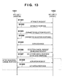
- Fig. 13 is a sequence chart showing the sequence of performing data exchange in the active mode
- Fig. 14 is a sequence chart for explaining transmission/reception of an access key for WLAN communication
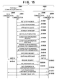
- Fig. 15 is a sequence chart showing the sequence of communication switching according to the embodiment.
- Fig. 16 is a flowchart showing the procedure of executing printing in the portable communication terminal.
- first communication a short distance wireless communication method
- second communication high-speed wireless communication
- a printing method using a technique of performing authentication using a short distance wireless communication method such as NFC (Near Field Communication) and then handing over the communication to wireless communication of another communication method will be explained.
- Fig. 1 is a view showing the arrangement of a wireless communication system according to this embodiment.
- This system includes a portable communication terminal 200 (a portable terminal as an example of an information processing apparatus), and MFPs (Multi Function Printers) 100 and 101.
- the portable communication terminal 200 has at least two types of wireless communication methods capable of executing communication using different authentication methods and different communication speeds.
- the portable communication terminal 200 need only be an apparatus capable of handling files of print targets, for example, a personal information terminal such as a PDA (Personal Digital Assistant), a mobile phone, or a digital camera.
- the MFP 100 that is an example of a print apparatus has a reading function of reading a document placed on a platen glass, and a printing function using a printing unit such as an inkjet printer.
- the MFP 100 may also have a FAX function and a telephone function.
- the portable communication terminal 200 and the MFP 100 communicate via WLAN. That is, the portable communication terminal 200 and the MFP 100 can perform peer to peer (P2P) communication by authenticating each other because both have the WLAN function.
- the portable communication terminal 200 and the MFP 101 communicate via NFC.
- Fig. 2 is a view showing the outer appearance of the portable communication terminal 200.
- a smartphone is used as the portable communication terminal 200.
- the smartphone is a multifunctional mobile phone including a camera, a network browser, a mail function, and the like as well as the functions of a mobile phone.
- An NFC unit 201 performs communication using NFC. Actually, communication can be performed when the user moves the NFC unit 201 close to within about 10 cm of the NFC unit of the communication partner.
- a WLAN unit 202 is a unit used to perform communication by WLAN and is provided in the apparatus. Note that the communication range of WLAN is wider than the communication range (about 10 cm) of the above-described NFC.
- a display unit 203 is a display having an LCD display mechanism.
- An operation unit 204 includes a touch-panel operation mechanism and detects press by the user. As a representative operation method, the display unit 203 displays button-shaped images, and when the user presses the operation unit 204, an event of press on a button is issued.
- a power supply key 205 is used by the user to power on/off the apparatus.
- Figs. 3A and 3B are views showing the outer appearance of the MFP.
- a platen glass 301 is a transparent glass table and is used to place a document to be read by a scanner.
- a document cover 302 is used to prevent reading light from externally leaking at the time of reading by the scanner.
- a printing paper insert port 303 is used to set paper sheets of various sizes. The paper sheets set in the printing paper insert port 303 are conveyed to the printing unit one by one, undergo desired printing, and are discharged from a printing paper discharge port 304.
- An operation display unit 305 and an NFC unit 306 are provided on the document cover 302. The operation display unit 305 will be described later with reference to Figs. 4A and 4B .
- the NFC unit 306 is a unit used to perform short distance wireless communication and a portion where the user actually sets close to the communication partner. The effective range of contact is about 10 cm from the NFC unit 306.
- a WLAN antenna 307 is used to perform communication by WLAN.
- FIGs. 4A and 4B are views showing examples of display on the portable communication terminal 200.
- An image selection screen shown in Fig. 4A illustrates an example in which the thumbnails of printing candidates are displayed.
- a thumbnail 401 is the thumbnail of each image data saved in the portable communication terminal 200 or a server apparatus (not shown).
- a focus 402 is displayed to indicate that the image is the print target.
- the user can select a plurality of print target images.
- a plurality of focuses 402 exist on the display unit 203. If not all the thumbnails can be displayed in one screen, scroll display may be performed.
- the user presses a print start key 403 to transmit the print job to the print apparatus.
- a printer selection screen shown in Fig. 4B illustrates an example of a printer selection screen.
- printers A and B are found by a search using WLAN.
- a printer A 404 shows a WLAN connection state including the information of the network name, signal strength, encryption, channel, MAC address, access key, and the like.
- the network name is a character string arbitrarily settable by the user.
- the signal strength indicates the strength of the radio signal. Encryption represents whether the signal is encrypted.
- the channel indicates the frequency width necessary for data transmission/reception.
- the MAC address is identification information assigned to each wireless communication apparatus in WLAN communication.
- the access key is a value (authentication information) used for authentication at the time of access by WLAN. Whether to set the access key is left to the user's discretion. If the access key is set, it needs to be input when accessing the MFP.
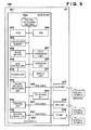
- Fig. 5 is a block diagram of the portable communication terminal 200.
- the portable communication terminal 200 includes a main board 501 that performs main control of the apparatus, a WLAN unit 517 that performs WLAN communication, an NFC unit 518 that performs NFC communication, and a BT unit 521 that performs Bluetooth ® communication.
- a CPU 502 of the main board 501 is a system control unit and controls the entire portable communication terminal 200.
- a ROM 503 stores control programs, an embedded operating system (OS) program, and the like to be executed by the CPU 502.
- OS operating system
- each control program stored in the ROM 503 performs software control such as scheduling and task switching under the management of the-embedded OS stored in the ROM 503.
- a RAM 504 is formed from an SRAM (static RAM) or the like.
- the RAM 504 stores program control variables, set values registered by the user, management data of the portable communication terminal 200, and the like, and also includes various kinds of work buffer areas.
- An image memory 505 is formed from a DRAM (dynamic RAM) or the like. The image memory 505 temporarily stores image data received via each communication unit or image data read out from a data storage unit 512 for processing by the CPU 502.
- a non-volatile memory 522 is formed from a flash memory or the like and stores data to be saved even after power-off. Examples of the data are telephone directory data and information of devices connected in the past. Note that the memory structure is not limited to this.
- the image memory 505 and the RAM 504 may share a memory, or data may be backed up in the data storage unit 512.
- a DRAM is used.
- a hard disk, a non-volatile memory, or the like may be used.
- a data conversion unit 506 performs analysis of a data description language (PDL) or data conversion such as color conversion and image conversion.
- a telephone unit 507 controls a telephone line and processes voice data input/output via a speaker unit 513 to implement communication by telephone.
- An operation unit 508 controls the signal of the operation unit 204 described with reference to Fig. 2 .
- a GPS (Global Positioning System) 509 obtains the current latitude and longitude.
- a display unit 510 electronically controls the display contents of the display unit 203 described with reference to Fig. 2 and can display various kind of input operations, the operation state and status of the connected print apparatus, and the like.
- a camera unit 511 has a function of electronically recording and coding an image input via a lens.
- the image captured by the camera unit 511 is saved in a data storage unit 512.
- the speaker unit 513 implements a function of inputting or outputting a voice for the telephone function, an alarm notification function, and the like.
- a power supply unit 514 is, for example, a portable battery and controls the power supply. Power supply states include a battery dead state corresponding to a zero battery level, a power off state before the user presses the power supply key 205, an active state in which the apparatus is normally activated, and a power saving state in which the apparatus is activated, but the power is saved.
- the portable communication terminal 200 includes three components used for wireless communication.
- the portable communication terminal 200 can perform wireless communication by WLAN, NFC, and Bluetooth ® .
- the WLAN unit 517, the NFC unit 518, and the BT unit 521 are communication units that perform data communication with another apparatus such as an MFP.
- Each of the units 517, 518, and 521 converts data into packets and transmits the packets to another apparatus. Reversely, each unit converts packets from another external apparatus into data and transmits the data to the CPU 502.
- the WLAN unit 517, the NFC unit 518, and the BT unit 521 are connected to a system bus 519 by bus cables 515, 516, and 520, respectively.
- the WLAN unit 517, the NFC unit 518, and the BT unit 521 are units configured to implement communication complying with the standards. Details of the NFC unit 518 will be described later with reference to Fig. 7 .
- the above-described units 503 to 514, 517, 518, 521, and 522 are connected to each other via the system bus 519 managed by the CPU 502.
- Fig. 6 is a block diagram showing the schematic arrangement of the MFPs 100 and 101. Although the MFP 100 will be described below, the description also applies to the MFP 101.
- the MFP 100 includes a main board 601 that performs main control of the apparatus, a WLAN unit 617 that performs WLAN communication, an NFC unit 618 that performs NFC communication, and a BT unit 619 that performs Bluetooth ® communication.
- a CPU 602 of the main board 601 is a system control unit and controls the entire MFP 100.
- a ROM 603 stores control programs, an embedded operating system (OS) program, and the like to be executed by the CPU 602.
- OS embedded operating system
- each control program stored in the ROM 603 performs software control such as scheduling and task switching under the management of the embedded OS stored in the ROM 603.
- a RAM 604 is formed from an SRAM (static RAM) or the like.
- the RAM 604 stores program control variables, set values registered by the user, management data of the MFP 100, and the like, and also includes various kinds of work buffer areas.
- a non-volatile memory 605 is formed from a flash memory or the like and stores data to be held even after power-off. Examples of the data are network connection information and user data.
- An image memory 606 is formed from a DRAM (dynamic RAM) or the like. The image memory 606 stores image data received via each communication unit, image data processed by a coding/decoding processing unit 612, and the like. Like the memory structure of the portable communication terminal 200, the memory structure is not limited to the above-described structure.
- a data conversion unit 607 performs analysis of a data description language (PDL) or conversion of image data into print data.
- PDL data description language
- a read control unit 608 will be described.
- a reading unit 610 optically reads a document by a CIS image sensor (contact type image sensor). Next, the reading unit 610 performs, for the image signal converted into electrical image data, various kinds of image processing such as binarization processing and halftone processing via an image processing control unit (not shown) and outputs high-resolution image data.
- An operation unit 609 is used by the user to perform operations, and various forms are used.
- the operation unit may include hard keys such as a 4-way selector, a set key, and a stop key or use a touch panel.
- a display unit 611 uses, for example, a dot matrix LCD.
- the coding/decoding processing unit 612 performs coding/decoding processing or enlargement/reduction processing for the image data (JPEG, PNG, or the like) handled by the MFP 100.
- a paper feed unit 614 holds printing paper sheets.
- the paper feed unit 614 can feed paper under the control of a print control unit 616.
- the paper feed unit 614 may include a plurality of paper feed units to hold a plurality of kinds of printing paper sheets in one apparatus.
- the print control unit 616 controls from which the paper feed unit feeds paper.
- the print control unit 616 converts the image data to be printed into high-resolution image data by performing various kinds of image processing such as smoothing processing, printing density correction processing, and color correction via the image processing control unit (not shown) and outputs the image data to a printing unit 615.
- the print control unit 616 also has a function of periodically reading out the information of the printing unit and updating the information in the RAM 604.
- the information of the printing unit includes, for example, the ink amount remaining in the ink tank and the state of the printhead.
- the MFP 100 also includes three components used for wireless communication with the portable communication terminal 200, as described above.
- the units 603 to 619 are communicably connected to each other via a system bus 623 managed by the CPU 602.
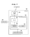
- Fig. 7 is a block diagram showing the detailed arrangement of an NFC unit 700 used as the NFC unit 518 or the NFC unit 618.
- the NFC unit 700 includes an NFC controller unit 701, an antenna unit 702, an RF unit 703, a transmission/reception control unit 704, an NFC memory 705, a power supply 706, and a device connection unit 707.
- the antenna unit 702 receives a radio wave or a carrier from another NFC device or transmits a radio wave or a carrier to another NFC device.
- the RF unit 703 has a function of modulating/demodulating an analog signal into a digital signal.
- the RF unit 703 includes a synthesizer, identifies the frequency of a band or a channel, and controls the band or channel by frequency assignment data.
- the transmission/reception control unit 704 performs control concerning transmission/reception, including frame segmentation and reassembly, preamble addition and detection, and frame identification.
- the transmission/reception control unit 704 also controls the NFC memory 705 and reads/writes various kinds of data and programs.
- the NFC unit 700 When the NFC unit 700 operates in the active mode, it receives power via the power supply 706.
- the NFC unit 700 communicates with a device via the device connection unit 707 or communicates with another NFC device within a communication range by generating an electromotive force in the device by electromagnetic induction using a carrier transmitted/received via the antenna unit 702.
- the NFC unit 700 when the NFC unit 700 operates in the passive mode, it receives a carrier from another NFC device via the antenna and receives power from the other NFC device on the communication partner side by electromagnetic induction.
- the NFC unit 700 then communicates with the other NFC device by modulating the carrier, thereby transmitting/receiving a carrier.
- NFC communication When short distance wireless communication using the NFC unit is performed, an apparatus that starts the short distance wireless communication first by sending an RF field (Radio Frequency field) is called an initiator. An apparatus that communicates with the initiator by responding to a command issued by the initiator is called a target.
- the NFC unit has a passive mode and an active mode as the communication modes. In the passive mode, the target responds to the command of the initiator by performing load modulation of the RF field sent from the initiator. On the other hand, in the active mode, the target responds to the command of the initiator by sending an RF field by itself.
- Figs. 9A and 9B are views showing the concept of the passive mode in NFC communication.
- the initiator 901 when an initiator 901 is to transmit data 904 to a target 902 in the passive mode, the initiator 901 generates an RF field 903.
- the initiator 901 modulates the RF field 903 by itself, thereby transmitting the data 904 to the target 902.
- a target 906 when a target 906 is to transfer data 908 to an initiator 905 in the passive mode, the initiator 905 generates an RF field 907, as in Fig. 9A .
- the target 906 performs load modulation of the RF field 907, thereby transmitting the data 908 to the initiator 905.
- Figs. 10A and 10B are views showing the concept of the active mode in NFC communication.
- the initiator 1001 when an initiator 1001 is to transmit data 1004 to a target 1002 in the active mode, the initiator 1001 generates an RF field 1003.
- the initiator 1001 modulates the RF field 1003 by itself, thereby transmitting the data 1004 to the target 1002.
- the initiator 1001 stops outputting the RF field 1003.
- Fig. 10B when a target 1006 is to transmit data 1008 to an initiator 1005 in the active mode, the target 1006 generates an RF field 1007.
- the target 1006 transmits the data 1008 by the RF field 1007 generated by itself and stops outputting the RF field 1007 upon completing transmission.
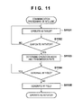
- Fig. 11 is a flowchart showing the procedure of causing an NFC unit to operate as an initiator. Each process shown in Fig. 11 is executed by the CPU and the like of the apparatus incorporating the NFC unit.
- step S1101 every NFC unit operates as a target and waits for a command from an initiator.
- step S1102 the NFC unit can switch to an initiator in response to a request from an application that controls communication complying with the NFC standards. If the NFC unit has responded to the request to switch to the initiator, the application selects one of the active mode and the passive mode and decides the transmission rate in step S1103.
- the initiator detects the existence of an RF field output from an apparatus other than itself.
- the initiator Upon detecting the existence of an external RF field, the initiator does not generate the RF field of its own. If the existence of an external RF field is not detected, the process advances to step S1105, and the initiator generates the RF field of its own. With the above-described processes, the NFC unit starts the operation as the initiator.
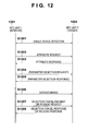
- Fig. 12 is a sequence chart showing the sequence of performing data exchange in the passive mode.
- a first NFC unit 1201 operates as the initiator, and a second NFC unit 1202 operates as a target.
- the first NFC unit 1201 performs single device detection and specifies the second NFC unit 1202. That is, in step S1201, the first NFC unit 1201 and the second NFC unit 1202 detect each other's existence.
- the first NFC unit 1201 transmits the identifier of its own, the bit transmission rate of transmission/reception, the effective data length, and the like to the partner as an attribute request.
- the attribute request has general purpose bytes which can arbitrarily be selected and used.
- the second NFC unit 1202 Upon receiving an effective attribute request, transmits an attribute response in step S1203. Transmission from the second NFC unit 1202 is done by load modulation. Data transmission by load modulation is indicated by a dotted arrow in Fig. 12 .
- the first NFC unit 1201 can change the parameters of the subsequent transmission protocol by transmitting a parameter selection request in step S1204.
- Parameters included in the parameter selection request are, for example, the transmission rate and the effective data length.
- the second NFC unit 1202 Upon receiving an effective parameter selection request, transmits a parameter selection response in step S1205 so as to change the parameters. Note that steps S1204 and S1205 may be omitted if the parameter change is not to be performed.
- step S1206 the first NFC unit 1201 and the second NFC unit 1202 exchange data by a data exchange request and a data exchange response.
- data exchange request and the data exchange response information for an application provided in the communication partner or the like can be transmitted as data. If the data size is large, the data can divisionally be transmitted.
- step S1207 the first NFC unit 1201 transmits one of a selection cancel request and a release request.
- the second NFC unit 1202 transmits a selection cancel response in step S1208.
- the first NFC unit 1201 releases the attribute representing the second NFC unit 1202, and the process returns to step S1201.
- the release request is transmitted, the second NFC unit 1202 transmits a release response in step S1208 and returns the initial state.
- the first NFC unit 1201 may return to the initial state because the target is completely released.
- Fig. 13 is a sequence chart showing the sequence of performing data exchange in the active mode.
- a first NFC unit 1301 operates as the initiator, and a second NFC unit 1302 operates as a target.
- the first NFC unit 1301 transmits the identifier of its own, the bit transmission rate of transmission/reception, the effective data length, and the like as an attribute request.
- the second NFC unit 1302 Upon receiving an effective attribute request, transmits an attribute response in step S1302. Transmission from the second NFC unit 1302 is done by an RF field generated by itself. For this reason, the first and second NFC units stop outputting the RF fields when ending data transmission.
- the first NFC unit 1301 can change the parameters of the transmission protocol by transmitting a parameter selection request in step S1303.
- Parameters included in the parameter selection request are the transmission rate and the effective data length.
- the second NFC unit 1302 Upon receiving an effective parameter selection request, transmits a parameter selection response in step S1304 so as to change the parameters. Note that steps S1303 and S1304 may be omitted if the parameter change is not to be performed, as in the passive mode.
- step S1305 the first NFC unit 1301 and the second NFC unit 1302 exchange data by a data exchange request and a data exchange response.
- data exchange request and the data exchange response information for an application or the like can be transmitted as data. If the data size is large, the data can divisionally be transmitted.
- step S1306 the first NFC unit 1301 transmits one of a selection cancel request and a release request.
- the second NFC unit 1302 transmits a selection cancel response in step S1307.
- the first NFC unit 1301 releases the attribute representing the second NFC unit 1302.
- step S1308 the first NFC unit 1301 transmits an activation request to another target whose identifier is known.
- the target transmits an activation response in step S1309, and the process returns to step S1301.
- the release request is transmitted in step S1306, the second NFC unit 1302 transmits a release response in step S1307 and returns the initial state.
- the first NFC unit 1301 may return to the initial state because the target is completely released.
- Fig. 16 is a flowchart showing the procedure until printing in the print apparatus is executed from the portable communication terminal. Each process shown in Fig. 16 is executed by the CPU 502 and the like of the portable communication terminal.
- step S1601 the user selects a photo to be printed using the portable communication terminal 200. For example, the function described concerning the image selection screen shown in Fig. 4A is used.
- the focus 402 is displayed.
- the process advances to step S1602.
- the portable communication terminal 200 When the user selects a print apparatus on the printer selection screen shown in Fig. 4B , the portable communication terminal 200 generates a print job that sets the selected image data as the print target in step S1603.
- the user may detect the print apparatus by bringing the NFC unit of the portable communication terminal 200 close to the NFC unit of the print apparatus and transmit the generated print job to the print apparatus. If no focus 402 is displayed at all, the portable communication terminal 200 sends no RF field not to detect the print apparatus by NFC. If at least one focus 402 is selected, the portable communication terminal sends an RF field because printing can be performed based on the selected image data. When the user additionally selects the thumbnail 401 during sending of the RF field, a focus is additionally displayed. This allows the user to select a print apparatus while selecting photos and also prevent an operation error (for example, erroneous execution of printing) caused by unintended NFC contact when no photo is selected.
- an operation error for example, erroneous execution of printing
- Fig. 8 is a flowchart showing the procedure of a communication control method of causing the portable communication terminal 200 to select a print apparatus by both WLAN communication and NFC communication and then performing selection control of WLAN communication and NFC communication.
- Each process shown in Fig. 8 is executed by the CPU 502 of the portable communication terminal 200.
- the processes shown in Fig. 8 are executed in steps S1602 and S1603 of Fig. 16 .
- step S801 the portable communication terminal 200 searches, via WLAN, for a print apparatus capable of printing image data the user has specified on the portable communication terminal 200.
- the NFC unit of the portable communication terminal 200 is shifted from the target mode to the initiator mode and thus set in a state capable of detecting a print apparatus in close vicinity. Processing of performing communication in the initiator mode has been described above with reference to Fig. 11 .
- a printer is searched for by WLAN, and simultaneously, the portable communication terminal is changed to the initiator to search for a printer by NFC as well.
- a printer found by the WLAN or NFC search method can be specified as the candidate of the apparatus to be caused to execute printing.
- step S803 a list of print apparatuses capable of printing in the communication range, which are found in step S801, is displayed on the printer selection screen shown in Fig. 4B .
- step S804 it is determined whether a print apparatus desired by the user is selected on the print apparatus list displayed in step S803.
- the process advances to step S817 to transmit a print job to the print apparatus via WLAN and cause the print apparatus to print.
- step S805 the process advances to step S805 to determine whether the NFC unit of the portable communication terminal 200 has detected a print apparatus in close vicinity.
- step S806 Upon determining that a print apparatus is detected, the process advances to step S806.
- Steps S804 and S805 are executed at a short periodical interval.
- step S806 mutual device authentication is performed between the MFP 101 and the portable communication terminal 200 via NFC.
- the mutual device authentication is performed using, for example, a device name arbitrarily set by the user, the serial ID of the MFP unique to each device, the model number of the MFP, capability information representing the capability of the MFP, NFC-ID, or information about LAN.
- Information about LAN includes, for example, items described concerning the printer selection screen shown in Fig. 4B . Instead, the system may be defined to exchange unique information.
- step S807 it is determined whether the print apparatus that matches the MFP 101 detected in step S805 exists in the list of print apparatuses found by WLAN in step S803.
- Examples of information used to determine whether the print apparatus matches are the MAC address, network name, and the serial ID of the MFP. Any other uniquely decided information may be used if it can uniquely specify a print apparatus.
- the portable communication terminal 200 transmits a print job to the MFP 101 via NFC in step S808.
- the print job describes the print settings and the image data storage location.
- the print settings are, for example, information such as the print mode and the paper size.
- the image data storage location includes the image data name, the address of the apparatus in which the image data is stored, path information to the storage location, the connection ID, and the like.
- the print job can be transmitted in step S808. For this reason, even if the printer desired by the user is not found by WLAN, the printer can be caused to execute printing.
- Steps S809 to S812 correspond to processing of switching the communication method (handover) and performing printing.
- switching is done between two different communication methods. Authentication for a high-speed communication method is performed using a low-speed secure communication method. After that, image data having a larger size is communicated using the high-speed communication method. Details will be described later with reference to Fig. 15 .
- step S809 the communication method is switched based on whether switching information exists.
- step S818, the print apparatus is caused to execute printing.
- Steps S813 to S816 correspond to processing of switching to communication via WLAN because the print apparatus detected via NFC exists in the list of print apparatuses found via WLAN.
- step S813 it is determined whether the WLAN is protected. This determination is done based on, for example, whether a network key is necessary for connecting to the print apparatus of the WLAN connection destination.
- the process advances to step S815.
- step S814 since the network key is unnecessary, the portable communication terminal 200 directly switches to communication via WLAN and is connected to the print apparatus via WLAN.
- the network key is received from the portable communication terminal 200 via NFC.
- step S816 the portable communication terminal 200 establishes communication with the print apparatus via WLAN using the network key. Details of step S815 will be described later with reference to Fig. 14 .
- step S817 communication is performed by selected WLAN.
- step S818, the print apparatus is caused to execute printing.
- step S806 Even when the portable communication terminal and the print apparatus are connected by NFC, as in step S806, the print apparatus that has been found by the search method using WLAN is connected by WLAN, as in step S814 or S816.
- the communication range is wider in WLAN than in NFC. For this reason, even if the user has moved with the portable communication terminal carried with him/her after NFC communication in step S806, communication can be performed by WLAN.
- steps S801 to S803 allow the user to select a print apparatus found by wireless communication such as WLAN when selecting a print apparatus and also select a print apparatus by short distance wireless communication such as NFC.
- the processes in steps S804 and S805 also allow the user to easily select one of two different types of communication methods.
- step S807 allows to automatically change the communication method so as to use WLAN if a print apparatus is specified via short distance wireless communication (first wireless communication) such as NFC, provided that a communication method (second wireless communication) having a higher speed such as WLAN exists.
- first wireless communication short distance wireless communication
- second wireless communication second wireless communication
- the access key can be transmitted/received via NFC. As a result, the user need not separately perform an operation of obtaining the access key.
- Fig. 14 shows a sequence for explaining details of step S815.
- a portable communication terminal 1401 sends a connection request to an MFP 1402 that is a print apparatus via WLAN.
- the MFP 1402 requests an access key of the portable communication terminal 1401.
- the portable communication terminal 1401 requests the access key of the MFP 1402 by NFC (step S1403), and the MFP 1402 transmits the access key to the portable communication terminal 1401 by NFC communication (step S1404: authentication information reception).
- the MFP 1402 may authenticate the portable communication terminal 1401 using a communication method other than NFC communication. For example, another authentication ID may be defined in advance by NFC communication, and authentication control may be done so as to perform authentication for WLAN communication only when the authentication has normally been done.
- the portable communication terminal 1401 transmits the obtained access key to the MFP 1402, and the MFP 1402 authenticates the portable communication terminal 1401 for WLAN communication.
- the MFP 1402 establishes connection to the portable communication terminal 1401 by WLAN.
- the MFP 1402 transfers the access key in response to the request from the portable communication terminal 1401. However, if the portable communication terminal 1401 knows the access key in advance, WLAN authentication may be done via NFC.
- Fig. 15 is a sequence chart showing processing of causing a portable communication terminal 1501 to transmit a print job via NFC and then switch to WLAN communication and transfer image data so as to cause an MFP 1502 that is a print apparatus to print the image data existing on the portable communication terminal 1501.
- the processing on the portable communication terminal side shown in Fig. 15 is executed by, for example, the CPU 502, and the processing on the print apparatus side is executed by, for example, the CPU 602.
- an NFC communication unit 1503 serves as an initiator and detects an NFC communication unit 1505 as a target.
- the NFC communication unit 1505 transmits a detection response in step S1502.
- the NFC communication unit 1503 transmits an attribute request to perform NFC communication in step S1503.
- the NFC communication unit 1505 returns an attribute response in step S1504.
- the NFC-IDs of the initiator and target are transmitted, and the communication partners are specified by the IDs.
- step S1505 mutual authentication is performed so that an encryption key for data encryption and the like can be transferred. Note that the mutual authentication need not be performed if, for example, no encryption key need be transferred.
- step S1506 the NFC communication unit 1503 requests information of a communication protocol usable by the print apparatus 1502 of the NFC communication unit 1505. This request includes information of a communication protocol usable by the portable communication terminal 1501. Upon receiving the request, the NFC communication unit 1505 can recognize that the WLAN communication of the portable communication terminal 1501 is usable.
- step S1507 the NFC communication unit 1505 returns information of a communication protocol usable by itself in response to the request received in step S1506. This allows both apparatuses to recognize the each other's usable communication protocols.
- step S1508 information such as an address for specifying the partner, which is necessary for performing WLAN communication, is exchanged.
- step S1510 the NFC communication unit 1503 transmits a request to switch from NFC communication to WLAN communication.
- the NFC communication unit 1505 returns a response to the request in step S1511.
- step S1512 switching from the NFC communication unit 1503 to a WLAN communication unit 1504 is performed in step S1512, and switching from the NFC communication unit 1505 to a WLAN communication unit 1506 is performed in step S1513.
- step S1514 the NFC communication unit 1503 transmits a release request.
- the NFC communication unit 1505 transmits a release response in step S1515, and the NFC communication ends.
- step S1516 WLAN communication is performed based on the information for WLAN communication exchanged in steps S1508 and S1509.
- the WLAN communication unit 1504 confirms with the WLAN communication unit 1506 whether data transfer is possible.
- An example of the contents to be confirmed is the capacity of the free space used to temporarily save the image to be transferred to the print apparatus 1502.
- the WLAN communication unit 1506 Upon receiving the confirmation request, the WLAN communication unit 1506 transmits a response to the request in step S1517.
- the WLAN communication unit 1504 Upon obtaining a correct response and determining that data transfer is possible, transmits the image data existing in the portable communication terminal 1501 to the WLAN communication unit 1506 in step S1518. This allows to transfer data of a large size using a faster communication protocol.
- a printer is searched for, by using both WLAN and NFC.
- the user can search for a desired printer without designating one of the search methods. If a printer is found by NFC, this printer is designated as a printer to be caused to execute printing. This allows a printer installed closer to the user to execute printing.
- the print job is transmitted using WLAN. This allows to appropriately transmit the print job even if the distance between the portable communication terminal and the printer increases beyond the communication range of the NFC.
- NFC has been exemplified as short distance wireless communication.
- the present invention is not limited to this, and any other communication method may be used.
- WLAN has been described as an example of wireless communication different from NFC.
- another wireless communication method such as Bluetooth ® may be used.
- wireless communication has been exemplified.
- the present invention is not limited to this.
- a printer may be searched for by a plurality of wired communications, or a printer may be searched for by wireless communication and wired communication.
- printing has been exemplified as the contents of predetermined processing.
- the present invention is not limited to this, and the apparatus may be caused to execute various kinds of processing.
- aspects of the present invention can also be realized by a computer of a system or apparatus (or devices such as a CPU or MPU) that reads out and executes a program recorded on a memory device to perform the functions of the above-described embodiment(s), and by a method, the steps of which are performed by a computer of a system or apparatus by, for example, reading out and executing a program recorded on a memory device to perform the functions of the above-described embodiment(s).
- the program is provided to the computer for example via a network or from a recording medium of various types serving as the memory device (for example, computer-readable medium).
Landscapes
- Engineering & Computer Science (AREA)
- Theoretical Computer Science (AREA)
- Human Computer Interaction (AREA)
- Physics & Mathematics (AREA)
- General Physics & Mathematics (AREA)
- Signal Processing (AREA)
- Computer Networks & Wireless Communication (AREA)
- General Engineering & Computer Science (AREA)
- Multimedia (AREA)
- Databases & Information Systems (AREA)
- Astronomy & Astrophysics (AREA)
- Mobile Radio Communication Systems (AREA)
- Facsimiles In General (AREA)
Applications Claiming Priority (1)
| Application Number | Priority Date | Filing Date | Title |
|---|---|---|---|
| JP2012048620A JP5941300B2 (ja) | 2012-03-05 | 2012-03-05 | 情報処理装置、情報処理装置の制御方法、およびプログラム |
Publications (3)
| Publication Number | Publication Date |
|---|---|
| EP2637092A2 true EP2637092A2 (fr) | 2013-09-11 |
| EP2637092A3 EP2637092A3 (fr) | 2014-01-22 |
| EP2637092B1 EP2637092B1 (fr) | 2020-04-08 |
Family
ID=47877674
Family Applications (1)
| Application Number | Title | Priority Date | Filing Date |
|---|---|---|---|
| EP13000798.2A Active EP2637092B1 (fr) | 2012-03-05 | 2013-02-15 | Appareil de traitement d'informations, procédé de commande d'appareil de traitement d'informations et programme associé |
Country Status (4)
| Country | Link |
|---|---|
| US (2) | US9094780B2 (fr) |
| EP (1) | EP2637092B1 (fr) |
| JP (1) | JP5941300B2 (fr) |
| CN (2) | CN105072562B (fr) |
Cited By (6)
| Publication number | Priority date | Publication date | Assignee | Title |
|---|---|---|---|---|
| EP2858330A1 (fr) * | 2013-10-04 | 2015-04-08 | Canon Kabushiki Kaisha | Appareil, procédé et support d'enregistrement pour de commande de communication sans fil |
| EP2963905A3 (fr) * | 2014-07-04 | 2016-05-11 | Canon Kabushiki Kaisha | Appareil de communication, appareil de terminal, procédés de commande de celui-ci et programme |
| EP2981055B1 (fr) * | 2014-07-29 | 2017-02-22 | Seiko Epson Corporation | Dispositif de commande d'un appareil |
| EP3098704A4 (fr) * | 2014-04-07 | 2017-10-11 | Star Micronics Co., Ltd. | Système de commande pour dispositif de traitement d'informations utilisant un terminal portatif, terminal portatif, et procédé de commande et programme de commande pour dispositif de traitement d'informations |
| US10136317B2 (en) | 2014-08-08 | 2018-11-20 | Alibaba Group Holding Limited | Information pushing method, server, sharer client and third-party client |
| EP3825832A4 (fr) * | 2018-09-11 | 2021-09-08 | Huawei Technologies Co., Ltd. | Procédé de partage de données, interface utilisateur graphique, et dispositif électronique et système |
Families Citing this family (64)
| Publication number | Priority date | Publication date | Assignee | Title |
|---|---|---|---|---|
| CN101827363B (zh) * | 2009-03-03 | 2015-07-01 | 夏普株式会社 | 通信系统、信息处理系统及装置、图像形成系统及装置、便携信息终端装置 |
| JP5915338B2 (ja) * | 2012-03-30 | 2016-05-11 | ブラザー工業株式会社 | 通信装置 |
| JP5962146B2 (ja) | 2012-03-30 | 2016-08-03 | ブラザー工業株式会社 | 通信装置 |
| JP5966527B2 (ja) | 2012-03-30 | 2016-08-10 | ブラザー工業株式会社 | 通信装置 |
| JP6015265B2 (ja) * | 2012-09-13 | 2016-10-26 | ヤマハ株式会社 | 近接通信システム |
| JP6003629B2 (ja) | 2012-12-27 | 2016-10-05 | ブラザー工業株式会社 | プログラム、および携帯端末 |
| JP5945965B2 (ja) | 2013-02-28 | 2016-07-05 | ブラザー工業株式会社 | 通信機器 |
| JP6015499B2 (ja) | 2013-03-07 | 2016-10-26 | ブラザー工業株式会社 | プログラム、および携帯端末 |
| US9277066B2 (en) * | 2013-06-28 | 2016-03-01 | Canon Kabushiki Kaisha | Communication system, communication terminal, control method, and storage medium storing program |
| JP6218456B2 (ja) | 2013-06-28 | 2017-10-25 | キヤノン株式会社 | 印刷装置及び通信方法、並びに、プログラム |
| JP6180220B2 (ja) * | 2013-07-31 | 2017-08-16 | キヤノン株式会社 | 処理システムおよび制御方法 |
| KR20150024752A (ko) * | 2013-08-27 | 2015-03-09 | 삼성전자주식회사 | 저장 장치의 정보 갱신 방법, 화상 형성 장치, 화상 형성 장치 관리 시스템 및 모바일 단말 장치 |
| WO2015030786A1 (fr) * | 2013-08-30 | 2015-03-05 | Hewlett-Packard Development Company, L.P. | Interfaçage d'un dispositif de réalité augmentée |
| JP2015093395A (ja) * | 2013-11-11 | 2015-05-18 | 京セラドキュメントソリューションズ株式会社 | 画像形成装置、画像形成システム、画像形成方法 |
| JP6160492B2 (ja) * | 2014-01-10 | 2017-07-12 | 株式会社デンソー | 車両の無線通信装置 |
| JP2015159533A (ja) * | 2014-01-27 | 2015-09-03 | 株式会社リコー | 端末装置、画像処理システム、画像可視化装置の制御方法およびプログラム |
| US9648485B2 (en) * | 2014-02-03 | 2017-05-09 | Qualcomm Incorporated | Discovery of a neighbor awareness network (NAN) using a wake up message |
| JP6360316B2 (ja) | 2014-02-06 | 2018-07-18 | キヤノン株式会社 | 通信装置、その制御方法、及びプログラム |
| JP5980258B2 (ja) | 2014-03-11 | 2016-08-31 | キヤノン株式会社 | 情報処理装置、情報処理装置の制御方法及びプログラム |
| JP6257403B2 (ja) * | 2014-03-24 | 2018-01-10 | キヤノン株式会社 | 情報処理装置およびその制御方法、並びにプログラム |
| JP6452313B2 (ja) * | 2014-05-13 | 2019-01-16 | キヤノン株式会社 | 通信装置及びその制御方法、プログラム |
| JP6464573B2 (ja) * | 2014-05-30 | 2019-02-06 | ブラザー工業株式会社 | 情報処理プログラム、情報処理装置および情報処理装置の制御方法 |
| JP6701415B2 (ja) * | 2014-06-06 | 2020-05-27 | キヤノン株式会社 | 通信装置および制御方法およびプログラム |
| JP6357918B2 (ja) * | 2014-06-27 | 2018-07-18 | ブラザー工業株式会社 | 情報処理プログラム、情報処理装置および情報処理装置の制御方法 |
| WO2016003018A1 (fr) * | 2014-07-02 | 2016-01-07 | 엘지전자(주) | Terminal mobile, et procédé de commande correspondant |
| KR102214118B1 (ko) * | 2014-07-09 | 2021-02-09 | 엘지전자 주식회사 | 이동단말기 및 그 제어방법 |
| JP6459251B2 (ja) * | 2014-07-03 | 2019-01-30 | セイコーエプソン株式会社 | 通信端末装置、通信システム、プログラム、及び、通信端末装置の制御方法 |
| JP6204882B2 (ja) | 2014-07-16 | 2017-09-27 | キヤノン株式会社 | 情報処理装置、制御方法、並びにプログラム |
| US20160036498A1 (en) * | 2014-08-01 | 2016-02-04 | Htc Corporation | Method of Wireless Power Connection |
| JP6265873B2 (ja) | 2014-09-24 | 2018-01-24 | キヤノン株式会社 | モバイル端末とその制御方法、及びプログラム |
| JP6302399B2 (ja) | 2014-11-17 | 2018-03-28 | キヤノン株式会社 | 近距離無線通信部を備える画像形成装置、その制御方法、及びプログラム |
| JP6482262B2 (ja) * | 2014-12-11 | 2019-03-13 | キヤノン株式会社 | 通信装置および通信装置の制御方法、プログラム |
| JP6176229B2 (ja) * | 2014-12-15 | 2017-08-09 | コニカミノルタ株式会社 | 携帯端末およびプログラム |
| JP6596824B2 (ja) * | 2015-01-09 | 2019-10-30 | コニカミノルタ株式会社 | 携帯端末およびプログラム |
| JP6402638B2 (ja) * | 2015-01-22 | 2018-10-10 | ブラザー工業株式会社 | 画像形成システム、画像形成装置、画像形成方法およびプログラム |
| JP6557473B2 (ja) | 2015-01-23 | 2019-08-07 | キヤノン株式会社 | システム、通信装置、通信方法及びプログラム |
| JP6570260B2 (ja) | 2015-02-13 | 2019-09-04 | キヤノン株式会社 | 画像処理装置、プログラム、及びシステム |
| JP6610292B2 (ja) * | 2015-02-26 | 2019-11-27 | 株式会社リコー | 情報処理装置、情報処理プログラム、および情報処理システム |
| JP6481462B2 (ja) * | 2015-03-27 | 2019-03-13 | 富士ゼロックス株式会社 | 画像形成装置の検索方法、携帯端末及びプログラム |
| JP6525714B2 (ja) * | 2015-04-30 | 2019-06-05 | キヤノン株式会社 | 通信装置、通信装置の制御方法及びプログラム |
| JP6686321B2 (ja) | 2015-08-06 | 2020-04-22 | 株式会社リコー | プログラム、情報処理装置、第二の情報処理装置、情報処理方法、情報処理システム |
| JP2017056699A (ja) * | 2015-09-18 | 2017-03-23 | 東芝テック株式会社 | プリンタ |
| JP6601188B2 (ja) * | 2015-11-30 | 2019-11-06 | セイコーエプソン株式会社 | 電子機器、端末装置、無線ネットワーク切替え方法、無線通信接続方法、およびプログラム |
| JP6184580B1 (ja) * | 2016-01-29 | 2017-08-23 | キヤノン株式会社 | 情報処理装置、制御方法およびプログラム |
| JP6638459B2 (ja) * | 2016-02-22 | 2020-01-29 | ブラザー工業株式会社 | プログラム |
| JP6693218B2 (ja) * | 2016-03-25 | 2020-05-13 | ブラザー工業株式会社 | 近接通信装置のプログラム、携帯装置のプログラム、及びこれらの装置を備えるシステム |
| JP6282364B2 (ja) * | 2016-03-31 | 2018-02-21 | キヤノン株式会社 | 通信装置、プログラム及びおよび通信システム |
| JP6642251B2 (ja) * | 2016-04-28 | 2020-02-05 | コニカミノルタ株式会社 | 印刷プログラム及び会議システム |
| JP6769204B2 (ja) * | 2016-09-21 | 2020-10-14 | コニカミノルタ株式会社 | 画像形成装置、プログラム、および、画像形成システム |
| JP6929735B2 (ja) * | 2017-08-09 | 2021-09-01 | キヤノン株式会社 | 通信装置、制御方法及びプログラム |
| US20190124194A1 (en) * | 2017-10-23 | 2019-04-25 | Honeywell International Inc. | Near-field communication initiated bluetooth pairing between mobile device and gas detector |
| JP7035619B2 (ja) * | 2018-02-27 | 2022-03-15 | セイコーエプソン株式会社 | 端末装置、通信システム、プログラム及び表示制御方法 |
| JP7135342B2 (ja) * | 2018-03-02 | 2022-09-13 | ブラザー工業株式会社 | 端末装置のためのコンピュータプログラムと端末装置 |
| JP6536720B2 (ja) * | 2018-06-21 | 2019-07-03 | ブラザー工業株式会社 | 情報処理プログラム、情報処理装置および情報処理装置の制御方法 |
| JP6622874B2 (ja) * | 2018-08-24 | 2019-12-18 | キヤノン株式会社 | 印刷装置及びその制御方法及びプログラム |
| JP6622878B2 (ja) * | 2018-09-19 | 2019-12-18 | キヤノン株式会社 | 情報処理装置およびその制御方法、並びにプログラム |
| JP6645556B2 (ja) * | 2018-10-31 | 2020-02-14 | ブラザー工業株式会社 | プログラム、および携帯端末 |
| JP7180460B2 (ja) | 2019-03-07 | 2022-11-30 | ブラザー工業株式会社 | 原稿読取装置及び画像形成装置 |
| JP6738567B2 (ja) * | 2019-06-06 | 2020-08-12 | ブラザー工業株式会社 | 情報処理プログラム、情報処理装置および情報処理装置の制御方法 |
| JP6869314B2 (ja) * | 2019-11-21 | 2021-05-12 | キヤノン株式会社 | 通信装置及びその制御方法及びプログラム |
| JP6814271B2 (ja) * | 2019-11-25 | 2021-01-13 | キヤノン株式会社 | 情報処理装置およびその制御方法、並びにプログラム |
| JP7218748B2 (ja) * | 2020-07-17 | 2023-02-07 | ブラザー工業株式会社 | 情報処理プログラム、情報処理装置および情報処理装置の制御方法 |
| JP7308916B2 (ja) * | 2020-12-18 | 2023-07-14 | キヤノン株式会社 | 情報処理装置およびその制御方法、並びにアプリケーション |
| JP7005734B2 (ja) * | 2020-12-18 | 2022-01-24 | キヤノン株式会社 | 情報処理装置およびその制御方法、並びにプログラム |
Citations (1)
| Publication number | Priority date | Publication date | Assignee | Title |
|---|---|---|---|---|
| JP2007166538A (ja) | 2005-12-16 | 2007-06-28 | Canon Inc | 通信装置およびその制御方法及び通信システム |
Family Cites Families (17)
| Publication number | Priority date | Publication date | Assignee | Title |
|---|---|---|---|---|
| KR100565062B1 (ko) * | 2003-12-13 | 2006-03-30 | 삼성전자주식회사 | 무선망을 통해 프린터를 선택하여 인쇄하는 시스템 및 그방법 |
| JP2005210328A (ja) * | 2004-01-21 | 2005-08-04 | Fuji Xerox Co Ltd | 情報処理システム、データ供給装置、データ供給装置の制御方法及びプログラム |
| JP4670270B2 (ja) * | 2004-06-28 | 2011-04-13 | ソニー株式会社 | 通信システム及び通信装置 |
| US7965981B2 (en) * | 2006-09-29 | 2011-06-21 | Sony Ericsson Mobile Communications Ab | Device and method for content searching between peer devices |
| JP4352277B2 (ja) * | 2007-01-12 | 2009-10-28 | セイコーエプソン株式会社 | 通信システム及び携帯通信端末 |
| US20090192935A1 (en) | 2008-01-30 | 2009-07-30 | Kent Griffin | One step near field communication transactions |
| JP5149715B2 (ja) * | 2008-06-30 | 2013-02-20 | キヤノン株式会社 | 通信システム、通信装置及びその制御方法、プログラム |
| US9014736B2 (en) * | 2008-11-24 | 2015-04-21 | Plantronics, Inc. | Portable network device for the discovery of nearby devices and services |
| CN101520949A (zh) | 2009-03-27 | 2009-09-02 | 昆明理工大学 | 道路会车警示牌 |
| JP5333076B2 (ja) * | 2009-09-04 | 2013-11-06 | ブラザー工業株式会社 | 無線ネットワークに接続可能なデバイスとコンピュータプログラム |
| US20110162048A1 (en) * | 2009-12-31 | 2011-06-30 | Apple Inc. | Local device awareness |
| JP5229246B2 (ja) * | 2010-01-28 | 2013-07-03 | 富士通モバイルコミュニケーションズ株式会社 | 通信端末 |
| US20110183614A1 (en) * | 2010-01-25 | 2011-07-28 | Kabushiki Kaisha Toshiba | Communication terminal |
| CN102771064B (zh) * | 2010-02-26 | 2015-09-30 | Lg电子株式会社 | 电子设备及其操作方法 |
| JP2011210140A (ja) | 2010-03-30 | 2011-10-20 | Sony Corp | 通信装置、通信方法、情報処理装置、情報処理方法、プログラム、および情報処理システム |
| JP5924983B2 (ja) | 2012-03-05 | 2016-05-25 | キヤノン株式会社 | 情報処理装置、その制御方法およびプログラム |
| JP5991733B2 (ja) | 2012-03-05 | 2016-09-14 | キヤノン株式会社 | ネットワークシステム、情報処理装置、及び通信方法 |
-
2012
- 2012-03-05 JP JP2012048620A patent/JP5941300B2/ja active Active
-
2013
- 2013-02-15 EP EP13000798.2A patent/EP2637092B1/fr active Active
- 2013-02-26 US US13/777,446 patent/US9094780B2/en active Active
- 2013-03-05 CN CN201510425288.1A patent/CN105072562B/zh active Active
- 2013-03-05 CN CN201310069045.XA patent/CN103312383B/zh active Active
-
2015
- 2015-06-19 US US14/744,237 patent/US9503587B2/en active Active
Patent Citations (1)
| Publication number | Priority date | Publication date | Assignee | Title |
|---|---|---|---|---|
| JP2007166538A (ja) | 2005-12-16 | 2007-06-28 | Canon Inc | 通信装置およびその制御方法及び通信システム |
Cited By (16)
| Publication number | Priority date | Publication date | Assignee | Title |
|---|---|---|---|---|
| RU2602344C2 (ru) * | 2013-10-04 | 2016-11-20 | Кэнон Кабусики Кайся | Устройство связи, способ управления устройством связи и носитель записи |
| EP2858330A1 (fr) * | 2013-10-04 | 2015-04-08 | Canon Kabushiki Kaisha | Appareil, procédé et support d'enregistrement pour de commande de communication sans fil |
| US9723650B2 (en) | 2013-10-04 | 2017-08-01 | Canon Kabushiki Kaisha | Communication apparatus that disconnects a wireless connection after a service provided on the wireless connection is completed, depending on the service, method for controlling the same, and recording medium |
| EP3098704A4 (fr) * | 2014-04-07 | 2017-10-11 | Star Micronics Co., Ltd. | Système de commande pour dispositif de traitement d'informations utilisant un terminal portatif, terminal portatif, et procédé de commande et programme de commande pour dispositif de traitement d'informations |
| US10372391B2 (en) | 2014-07-04 | 2019-08-06 | Canon Kabushiki Kaisha | Communication apparatus, terminal apparatus, control methods thereof, and non-transitory computer-readable storage medium |
| EP2963905A3 (fr) * | 2014-07-04 | 2016-05-11 | Canon Kabushiki Kaisha | Appareil de communication, appareil de terminal, procédés de commande de celui-ci et programme |
| US9565320B2 (en) | 2014-07-04 | 2017-02-07 | Canon Kabushiki Kaisha | Communication apparatus, terminal apparatus, control methods thereof, and non-transitory computer-readable storage medium |
| US9674378B2 (en) | 2014-07-04 | 2017-06-06 | Canon Kabushiki Kaisha | Communication apparatus, terminal apparatus, control methods thereof, and non-transitory computer-readable storage medium |
| US9836260B2 (en) | 2014-07-04 | 2017-12-05 | Canon Kabushiki Kaisha | Communication apparatus, terminal apparatus, control methods thereof, and non-transitory computer-readable storage medium |
| US10635366B2 (en) | 2014-07-04 | 2020-04-28 | Canon Kabushiki Kaisha | Communication apparatus, terminal apparatus, control methods thereof, and non-transitory computer-readable storage medium |
| EP2981055B1 (fr) * | 2014-07-29 | 2017-02-22 | Seiko Epson Corporation | Dispositif de commande d'un appareil |
| US10136317B2 (en) | 2014-08-08 | 2018-11-20 | Alibaba Group Holding Limited | Information pushing method, server, sharer client and third-party client |
| US11063934B2 (en) | 2014-08-08 | 2021-07-13 | Advanced New Technologies Co., Ltd. | Information pushing method, server, sharer client and third-party client |
| EP3825832A4 (fr) * | 2018-09-11 | 2021-09-08 | Huawei Technologies Co., Ltd. | Procédé de partage de données, interface utilisateur graphique, et dispositif électronique et système |
| US11544019B2 (en) | 2018-09-11 | 2023-01-03 | Huawei Technologies Co., Ltd. | Data sharing method, graphical user interface, electronic device, and system |
| US11861247B2 (en) | 2018-09-11 | 2024-01-02 | Huawei Technologies Co., Ltd. | Data sharing method, graphical user interface, electronic device, and system |
Also Published As
| Publication number | Publication date |
|---|---|
| JP5941300B2 (ja) | 2016-06-29 |
| CN105072562A (zh) | 2015-11-18 |
| US9503587B2 (en) | 2016-11-22 |
| CN103312383B (zh) | 2015-07-29 |
| JP2013187568A (ja) | 2013-09-19 |
| CN105072562B (zh) | 2019-03-01 |
| US20130231051A1 (en) | 2013-09-05 |
| CN103312383A (zh) | 2013-09-18 |
| EP2637092A3 (fr) | 2014-01-22 |
| EP2637092B1 (fr) | 2020-04-08 |
| US20150288832A1 (en) | 2015-10-08 |
| US9094780B2 (en) | 2015-07-28 |
Similar Documents
| Publication | Publication Date | Title |
|---|---|---|
| EP2637092B1 (fr) | Appareil de traitement d'informations, procédé de commande d'appareil de traitement d'informations et programme associé | |
| JP6650004B2 (ja) | 通信システム、プログラム、および通信方法 | |
| US10142510B2 (en) | Print control apparatus and control method thereof | |
| US9516596B2 (en) | Apparatus and method | |
| JP5991733B2 (ja) | ネットワークシステム、情報処理装置、及び通信方法 | |
| US10659628B2 (en) | Processing apparatus and communication method | |
| US9665328B2 (en) | Image recording system, image recording apparatus, non-transitory storage medium storing instructions executable by image recording apparatus, mobile terminal, and non-transitory storage medium storing instructions executable by mobile terminal | |
| US20130229685A1 (en) | Information processing apparatus, control method and storage medium storing program | |
| US9730045B2 (en) | Communicating apparatus, communication method, and storage medium storing program | |
| KR102128911B1 (ko) | 통신 장치 및 그 제어 방법 | |
| EP3247168B1 (fr) | Appareil de communication, procédé de commande associé et programme | |
| US9596006B2 (en) | Information processing apparatus and power supply control method | |
| JP6228383B2 (ja) | 通信装置、通信方法、プログラム | |
| JP7646744B2 (ja) | 通信装置および制御方法およびプログラム | |
| US10306455B2 (en) | Communication apparatus, communication method, and non-transitory computer-readable storage medium | |
| JP2024105610A (ja) | 通信装置及びプログラム | |
| JP6642965B2 (ja) | 画像処理システム、画像処理装置、制御方法、及びプログラム |
Legal Events
| Date | Code | Title | Description |
|---|---|---|---|
| PUAI | Public reference made under article 153(3) epc to a published international application that has entered the european phase |
Free format text: ORIGINAL CODE: 0009012 |
|
| AK | Designated contracting states |
Kind code of ref document: A2 Designated state(s): AL AT BE BG CH CY CZ DE DK EE ES FI FR GB GR HR HU IE IS IT LI LT LU LV MC MK MT NL NO PL PT RO RS SE SI SK SM TR |
|
| AX | Request for extension of the european patent |
Extension state: BA ME |
|
| PUAL | Search report despatched |
Free format text: ORIGINAL CODE: 0009013 |
|
| AK | Designated contracting states |
Kind code of ref document: A3 Designated state(s): AL AT BE BG CH CY CZ DE DK EE ES FI FR GB GR HR HU IE IS IT LI LT LU LV MC MK MT NL NO PL PT RO RS SE SI SK SM TR |
|
| AX | Request for extension of the european patent |
Extension state: BA ME |
|
| RIC1 | Information provided on ipc code assigned before grant |
Ipc: H04W 4/06 20090101ALN20131216BHEP Ipc: G06F 3/12 20060101AFI20131216BHEP Ipc: H04W 8/00 20090101ALI20131216BHEP |
|
| 17P | Request for examination filed |
Effective date: 20140722 |
|
| RBV | Designated contracting states (corrected) |
Designated state(s): AL AT BE BG CH CY CZ DE DK EE ES FI FR GB GR HR HU IE IS IT LI LT LU LV MC MK MT NL NO PL PT RO RS SE SI SK SM TR |
|
| STAA | Information on the status of an ep patent application or granted ep patent |
Free format text: STATUS: EXAMINATION IS IN PROGRESS |
|
| 17Q | First examination report despatched |
Effective date: 20180323 |
|
| RIC1 | Information provided on ipc code assigned before grant |
Ipc: H04W 8/00 20090101ALI20190627BHEP Ipc: G06F 3/12 20060101AFI20190627BHEP Ipc: H04W 4/06 20090101ALN20190627BHEP Ipc: H04W 4/80 20180101ALN20190627BHEP |
|
| GRAP | Despatch of communication of intention to grant a patent |
Free format text: ORIGINAL CODE: EPIDOSNIGR1 |
|
| STAA | Information on the status of an ep patent application or granted ep patent |
Free format text: STATUS: GRANT OF PATENT IS INTENDED |
|
| INTG | Intention to grant announced |
Effective date: 20190819 |
|
| GRAS | Grant fee paid |
Free format text: ORIGINAL CODE: EPIDOSNIGR3 |
|
| GRAJ | Information related to disapproval of communication of intention to grant by the applicant or resumption of examination proceedings by the epo deleted |
Free format text: ORIGINAL CODE: EPIDOSDIGR1 |
|
| GRAL | Information related to payment of fee for publishing/printing deleted |
Free format text: ORIGINAL CODE: EPIDOSDIGR3 |
|
| STAA | Information on the status of an ep patent application or granted ep patent |
Free format text: STATUS: EXAMINATION IS IN PROGRESS |
|
| INTC | Intention to grant announced (deleted) | ||
| RAP1 | Party data changed (applicant data changed or rights of an application transferred) |
Owner name: CANON KABUSHIKI KAISHA |
|
| RIC1 | Information provided on ipc code assigned before grant |
Ipc: H04W 4/06 20090101ALN20200107BHEP Ipc: H04W 4/80 20180101ALN20200107BHEP Ipc: H04W 8/00 20090101ALI20200107BHEP Ipc: G06F 3/12 20060101AFI20200107BHEP |
|
| GRAR | Information related to intention to grant a patent recorded |
Free format text: ORIGINAL CODE: EPIDOSNIGR71 |
|
| STAA | Information on the status of an ep patent application or granted ep patent |
Free format text: STATUS: GRANT OF PATENT IS INTENDED |
|
| GRAA | (expected) grant |
Free format text: ORIGINAL CODE: 0009210 |
|
| STAA | Information on the status of an ep patent application or granted ep patent |
Free format text: STATUS: THE PATENT HAS BEEN GRANTED |
|
| INTG | Intention to grant announced |
Effective date: 20200213 |
|
| AK | Designated contracting states |
Kind code of ref document: B1 Designated state(s): AL AT BE BG CH CY CZ DE DK EE ES FI FR GB GR HR HU IE IS IT LI LT LU LV MC MK MT NL NO PL PT RO RS SE SI SK SM TR |
|
| REG | Reference to a national code |
Ref country code: AT Ref legal event code: REF Ref document number: 1255279 Country of ref document: AT Kind code of ref document: T Effective date: 20200415 Ref country code: CH Ref legal event code: EP |
|
| REG | Reference to a national code |
Ref country code: DE Ref legal event code: R096 Ref document number: 602013067592 Country of ref document: DE |
|
| REG | Reference to a national code |
Ref country code: IE Ref legal event code: FG4D |
|
| REG | Reference to a national code |
Ref country code: NL Ref legal event code: MP Effective date: 20200408 |
|
| REG | Reference to a national code |
Ref country code: LT Ref legal event code: MG4D |
|
| PG25 | Lapsed in a contracting state [announced via postgrant information from national office to epo] |
Ref country code: LT Free format text: LAPSE BECAUSE OF FAILURE TO SUBMIT A TRANSLATION OF THE DESCRIPTION OR TO PAY THE FEE WITHIN THE PRESCRIBED TIME-LIMIT Effective date: 20200408 Ref country code: PT Free format text: LAPSE BECAUSE OF FAILURE TO SUBMIT A TRANSLATION OF THE DESCRIPTION OR TO PAY THE FEE WITHIN THE PRESCRIBED TIME-LIMIT Effective date: 20200817 Ref country code: GR Free format text: LAPSE BECAUSE OF FAILURE TO SUBMIT A TRANSLATION OF THE DESCRIPTION OR TO PAY THE FEE WITHIN THE PRESCRIBED TIME-LIMIT Effective date: 20200709 Ref country code: SE Free format text: LAPSE BECAUSE OF FAILURE TO SUBMIT A TRANSLATION OF THE DESCRIPTION OR TO PAY THE FEE WITHIN THE PRESCRIBED TIME-LIMIT Effective date: 20200408 Ref country code: NL Free format text: LAPSE BECAUSE OF FAILURE TO SUBMIT A TRANSLATION OF THE DESCRIPTION OR TO PAY THE FEE WITHIN THE PRESCRIBED TIME-LIMIT Effective date: 20200408 Ref country code: NO Free format text: LAPSE BECAUSE OF FAILURE TO SUBMIT A TRANSLATION OF THE DESCRIPTION OR TO PAY THE FEE WITHIN THE PRESCRIBED TIME-LIMIT Effective date: 20200708 Ref country code: FI Free format text: LAPSE BECAUSE OF FAILURE TO SUBMIT A TRANSLATION OF THE DESCRIPTION OR TO PAY THE FEE WITHIN THE PRESCRIBED TIME-LIMIT Effective date: 20200408 Ref country code: IS Free format text: LAPSE BECAUSE OF FAILURE TO SUBMIT A TRANSLATION OF THE DESCRIPTION OR TO PAY THE FEE WITHIN THE PRESCRIBED TIME-LIMIT Effective date: 20200808 |
|
| REG | Reference to a national code |
Ref country code: AT Ref legal event code: MK05 Ref document number: 1255279 Country of ref document: AT Kind code of ref document: T Effective date: 20200408 |
|
| PG25 | Lapsed in a contracting state [announced via postgrant information from national office to epo] |
Ref country code: HR Free format text: LAPSE BECAUSE OF FAILURE TO SUBMIT A TRANSLATION OF THE DESCRIPTION OR TO PAY THE FEE WITHIN THE PRESCRIBED TIME-LIMIT Effective date: 20200408 Ref country code: LV Free format text: LAPSE BECAUSE OF FAILURE TO SUBMIT A TRANSLATION OF THE DESCRIPTION OR TO PAY THE FEE WITHIN THE PRESCRIBED TIME-LIMIT Effective date: 20200408 Ref country code: BG Free format text: LAPSE BECAUSE OF FAILURE TO SUBMIT A TRANSLATION OF THE DESCRIPTION OR TO PAY THE FEE WITHIN THE PRESCRIBED TIME-LIMIT Effective date: 20200708 Ref country code: RS Free format text: LAPSE BECAUSE OF FAILURE TO SUBMIT A TRANSLATION OF THE DESCRIPTION OR TO PAY THE FEE WITHIN THE PRESCRIBED TIME-LIMIT Effective date: 20200408 |
|
| PG25 | Lapsed in a contracting state [announced via postgrant information from national office to epo] |
Ref country code: AL Free format text: LAPSE BECAUSE OF FAILURE TO SUBMIT A TRANSLATION OF THE DESCRIPTION OR TO PAY THE FEE WITHIN THE PRESCRIBED TIME-LIMIT Effective date: 20200408 |
|
| REG | Reference to a national code |
Ref country code: DE Ref legal event code: R097 Ref document number: 602013067592 Country of ref document: DE |
|
| PG25 | Lapsed in a contracting state [announced via postgrant information from national office to epo] |
Ref country code: ES Free format text: LAPSE BECAUSE OF FAILURE TO SUBMIT A TRANSLATION OF THE DESCRIPTION OR TO PAY THE FEE WITHIN THE PRESCRIBED TIME-LIMIT Effective date: 20200408 Ref country code: RO Free format text: LAPSE BECAUSE OF FAILURE TO SUBMIT A TRANSLATION OF THE DESCRIPTION OR TO PAY THE FEE WITHIN THE PRESCRIBED TIME-LIMIT Effective date: 20200408 Ref country code: CZ Free format text: LAPSE BECAUSE OF FAILURE TO SUBMIT A TRANSLATION OF THE DESCRIPTION OR TO PAY THE FEE WITHIN THE PRESCRIBED TIME-LIMIT Effective date: 20200408 Ref country code: DK Free format text: LAPSE BECAUSE OF FAILURE TO SUBMIT A TRANSLATION OF THE DESCRIPTION OR TO PAY THE FEE WITHIN THE PRESCRIBED TIME-LIMIT Effective date: 20200408 Ref country code: IT Free format text: LAPSE BECAUSE OF FAILURE TO SUBMIT A TRANSLATION OF THE DESCRIPTION OR TO PAY THE FEE WITHIN THE PRESCRIBED TIME-LIMIT Effective date: 20200408 Ref country code: SM Free format text: LAPSE BECAUSE OF FAILURE TO SUBMIT A TRANSLATION OF THE DESCRIPTION OR TO PAY THE FEE WITHIN THE PRESCRIBED TIME-LIMIT Effective date: 20200408 Ref country code: EE Free format text: LAPSE BECAUSE OF FAILURE TO SUBMIT A TRANSLATION OF THE DESCRIPTION OR TO PAY THE FEE WITHIN THE PRESCRIBED TIME-LIMIT Effective date: 20200408 Ref country code: AT Free format text: LAPSE BECAUSE OF FAILURE TO SUBMIT A TRANSLATION OF THE DESCRIPTION OR TO PAY THE FEE WITHIN THE PRESCRIBED TIME-LIMIT Effective date: 20200408 |
|
| PLBE | No opposition filed within time limit |
Free format text: ORIGINAL CODE: 0009261 |
|
| STAA | Information on the status of an ep patent application or granted ep patent |
Free format text: STATUS: NO OPPOSITION FILED WITHIN TIME LIMIT |
|
| PG25 | Lapsed in a contracting state [announced via postgrant information from national office to epo] |
Ref country code: SK Free format text: LAPSE BECAUSE OF FAILURE TO SUBMIT A TRANSLATION OF THE DESCRIPTION OR TO PAY THE FEE WITHIN THE PRESCRIBED TIME-LIMIT Effective date: 20200408 Ref country code: PL Free format text: LAPSE BECAUSE OF FAILURE TO SUBMIT A TRANSLATION OF THE DESCRIPTION OR TO PAY THE FEE WITHIN THE PRESCRIBED TIME-LIMIT Effective date: 20200408 |
|
| 26N | No opposition filed |
Effective date: 20210112 |
|
| PG25 | Lapsed in a contracting state [announced via postgrant information from national office to epo] |
Ref country code: SI Free format text: LAPSE BECAUSE OF FAILURE TO SUBMIT A TRANSLATION OF THE DESCRIPTION OR TO PAY THE FEE WITHIN THE PRESCRIBED TIME-LIMIT Effective date: 20200408 |
|
| PG25 | Lapsed in a contracting state [announced via postgrant information from national office to epo] |
Ref country code: MC Free format text: LAPSE BECAUSE OF FAILURE TO SUBMIT A TRANSLATION OF THE DESCRIPTION OR TO PAY THE FEE WITHIN THE PRESCRIBED TIME-LIMIT Effective date: 20200408 |
|
| GBPC | Gb: european patent ceased through non-payment of renewal fee |
Effective date: 20210215 |
|
| REG | Reference to a national code |
Ref country code: BE Ref legal event code: MM Effective date: 20210228 |
|
| PG25 | Lapsed in a contracting state [announced via postgrant information from national office to epo] |
Ref country code: LU Free format text: LAPSE BECAUSE OF NON-PAYMENT OF DUE FEES Effective date: 20210215 Ref country code: LI Free format text: LAPSE BECAUSE OF NON-PAYMENT OF DUE FEES Effective date: 20210228 Ref country code: CH Free format text: LAPSE BECAUSE OF NON-PAYMENT OF DUE FEES Effective date: 20210228 |
|
| PG25 | Lapsed in a contracting state [announced via postgrant information from national office to epo] |
Ref country code: GB Free format text: LAPSE BECAUSE OF NON-PAYMENT OF DUE FEES Effective date: 20210215 Ref country code: FR Free format text: LAPSE BECAUSE OF NON-PAYMENT OF DUE FEES Effective date: 20210228 Ref country code: IE Free format text: LAPSE BECAUSE OF NON-PAYMENT OF DUE FEES Effective date: 20210215 |
|
| PG25 | Lapsed in a contracting state [announced via postgrant information from national office to epo] |
Ref country code: BE Free format text: LAPSE BECAUSE OF NON-PAYMENT OF DUE FEES Effective date: 20210228 |
|
| PG25 | Lapsed in a contracting state [announced via postgrant information from national office to epo] |
Ref country code: HU Free format text: LAPSE BECAUSE OF FAILURE TO SUBMIT A TRANSLATION OF THE DESCRIPTION OR TO PAY THE FEE WITHIN THE PRESCRIBED TIME-LIMIT; INVALID AB INITIO Effective date: 20130215 |
|
| PG25 | Lapsed in a contracting state [announced via postgrant information from national office to epo] |
Ref country code: CY Free format text: LAPSE BECAUSE OF FAILURE TO SUBMIT A TRANSLATION OF THE DESCRIPTION OR TO PAY THE FEE WITHIN THE PRESCRIBED TIME-LIMIT Effective date: 20200408 |
|
| PG25 | Lapsed in a contracting state [announced via postgrant information from national office to epo] |
Ref country code: MK Free format text: LAPSE BECAUSE OF FAILURE TO SUBMIT A TRANSLATION OF THE DESCRIPTION OR TO PAY THE FEE WITHIN THE PRESCRIBED TIME-LIMIT Effective date: 20200408 |
|
| PG25 | Lapsed in a contracting state [announced via postgrant information from national office to epo] |
Ref country code: MT Free format text: LAPSE BECAUSE OF FAILURE TO SUBMIT A TRANSLATION OF THE DESCRIPTION OR TO PAY THE FEE WITHIN THE PRESCRIBED TIME-LIMIT Effective date: 20200408 |
|
| PG25 | Lapsed in a contracting state [announced via postgrant information from national office to epo] |
Ref country code: TR Free format text: LAPSE BECAUSE OF FAILURE TO SUBMIT A TRANSLATION OF THE DESCRIPTION OR TO PAY THE FEE WITHIN THE PRESCRIBED TIME-LIMIT Effective date: 20200408 |
|
| PGFP | Annual fee paid to national office [announced via postgrant information from national office to epo] |
Ref country code: DE Payment date: 20260121 Year of fee payment: 14 |